EP0112959A2 - Joint - Google Patents
Joint Download PDFInfo
- Publication number
- EP0112959A2 EP0112959A2 EP83103853A EP83103853A EP0112959A2 EP 0112959 A2 EP0112959 A2 EP 0112959A2 EP 83103853 A EP83103853 A EP 83103853A EP 83103853 A EP83103853 A EP 83103853A EP 0112959 A2 EP0112959 A2 EP 0112959A2
- Authority
- EP
- European Patent Office
- Prior art keywords
- sealing lip
- groove
- acting
- sealing
- machine part
- Prior art date
- Legal status (The legal status is an assumption and is not a legal conclusion. Google has not performed a legal analysis and makes no representation as to the accuracy of the status listed.)
- Granted
Links
- 238000007789 sealing Methods 0.000 claims abstract description 69
- 230000004323 axial length Effects 0.000 claims 1
- 230000000694 effects Effects 0.000 description 5
- 239000007788 liquid Substances 0.000 description 5
- YAFQFNOUYXZVPZ-UHFFFAOYSA-N liproxstatin-1 Chemical compound ClC1=CC=CC(CNC=2C3(CCNCC3)NC3=CC=CC=C3N=2)=C1 YAFQFNOUYXZVPZ-UHFFFAOYSA-N 0.000 description 3
- 239000000463 material Substances 0.000 description 2
- 230000006835 compression Effects 0.000 description 1
- 238000007906 compression Methods 0.000 description 1
- 239000013013 elastic material Substances 0.000 description 1
- 230000002349 favourable effect Effects 0.000 description 1
- 238000006386 neutralization reaction Methods 0.000 description 1
- 230000035699 permeability Effects 0.000 description 1
- 230000002028 premature Effects 0.000 description 1
- 230000003068 static effect Effects 0.000 description 1
- 230000001960 triggered effect Effects 0.000 description 1
Images

Classifications
-
- F—MECHANICAL ENGINEERING; LIGHTING; HEATING; WEAPONS; BLASTING
- F16—ENGINEERING ELEMENTS AND UNITS; GENERAL MEASURES FOR PRODUCING AND MAINTAINING EFFECTIVE FUNCTIONING OF MACHINES OR INSTALLATIONS; THERMAL INSULATION IN GENERAL
- F16J—PISTONS; CYLINDERS; SEALINGS
- F16J15/00—Sealings
- F16J15/16—Sealings between relatively-moving surfaces
- F16J15/164—Sealings between relatively-moving surfaces the sealing action depending on movements; pressure difference, temperature or presence of leaking fluid
-
- F—MECHANICAL ENGINEERING; LIGHTING; HEATING; WEAPONS; BLASTING
- F16—ENGINEERING ELEMENTS AND UNITS; GENERAL MEASURES FOR PRODUCING AND MAINTAINING EFFECTIVE FUNCTIONING OF MACHINES OR INSTALLATIONS; THERMAL INSULATION IN GENERAL
- F16J—PISTONS; CYLINDERS; SEALINGS
- F16J15/00—Sealings
- F16J15/16—Sealings between relatively-moving surfaces
- F16J15/32—Sealings between relatively-moving surfaces with elastic sealings, e.g. O-rings
- F16J15/3204—Sealings between relatively-moving surfaces with elastic sealings, e.g. O-rings with at least one lip
- F16J15/3232—Sealings between relatively-moving surfaces with elastic sealings, e.g. O-rings with at least one lip having two or more lips
- F16J15/3236—Sealings between relatively-moving surfaces with elastic sealings, e.g. O-rings with at least one lip having two or more lips with at least one lip for each surface, e.g. U-cup packings
-
- F—MECHANICAL ENGINEERING; LIGHTING; HEATING; WEAPONS; BLASTING
- F16—ENGINEERING ELEMENTS AND UNITS; GENERAL MEASURES FOR PRODUCING AND MAINTAINING EFFECTIVE FUNCTIONING OF MACHINES OR INSTALLATIONS; THERMAL INSULATION IN GENERAL
- F16J—PISTONS; CYLINDERS; SEALINGS
- F16J15/00—Sealings
- F16J15/16—Sealings between relatively-moving surfaces
- F16J15/32—Sealings between relatively-moving surfaces with elastic sealings, e.g. O-rings
- F16J15/3268—Mounting of sealing rings
- F16J15/3276—Mounting of sealing rings with additional static sealing between the sealing, or its casing or support, and the surface on which it is mounted
Definitions
- the invention relates to a seal for the groove, which is open in the radial direction, of a stationary machine part relative to an axially displaceable machine part, consisting of an elastically flexible ring body and optionally a back ring, the ring body having an essentially rectangularly limited profile, which is extended on the pressure side to a statically acting first sealing lip which bears against the groove base and to a dynamically acting second sealing lip which bears against the axially displaceable machine part.
- Seals of the aforementioned type are usually referred to as groove rings. They are used to seal reciprocating piston rods or pistons against a pressurized liquid.
- a series connection of several grooved rings is common, which, however, is the case with the customary embodiments in which the dynamically acting sealing lip is at a greater or an identical distance from the assigned end face of the receiving groove compared to the statically acting sealing lip pressure build-up in the space between the individual grooved rings. This can result in premature failure.
- the invention has for its object to develop a grooved ring of the type mentioned in such a way that the disadvantages mentioned no longer occur.
- pressure build-up between the individual grooved rings should be avoided in a tandem arrangement.
- statically acting sealing lip is at a greater distance from the associated end face of the groove than the dynamically acting one
- Sealing lip The difference in conventional designs in the diameter range from 20 to 150 mm is 0.5 to 1.5 mm.
- a tilting movement of the profile of the groove ring is triggered such that the side of the seal facing away from the sealing lips is lifted off the relatively moving machine part.
- Leakage liquid carried along by the piston rod and possibly accumulated in the intermediate space to a further seal can thereby be returned to the sealed space to a substantially improved extent, where it is available for a further work cycle. If the grooving rings are arranged several times in succession, this also relieves the space in between, which ensures favorable operating conditions for the subsequent work cycle.
- the tilting effect can be favored "by a profile of the groove, which surrounds the groove ring on all sides at a distance except in the area of the sealing edges. Also in the axial direction, this results in a limited displaceability within the groove, which creates a gap between the dynamic during the working stroke.
- the neutralization of the liquid pressure between the annular space enclosed by the sealing lips and the mentioned end face and the work area at the beginning of each work cycle is thereby favored achieved when the second sealing lip on the pressure side in front of the sealing edge of at least one is broken in the radial direction extending channel. If there are several channels, these should be distributed as evenly as possible over the circumference.
- the channels can be opened in a U-shape in the axial direction or through the gaps extending in the axial direction knobs with boundary surfaces ending in a common radial plane, which in this case form the end face in its entirety.
- Tilting the profile of the proposed seal as a function of the direction of movement of the dynamically sealed machine part thus results in a valve effect which ensures a substantial interruption of the liquid flow when moving in the working direction and at the same time maximum permeability when moving against the working direction.
- the effect can be achieved by using grooved rings with sealing lips of equal length in the axial direction if the end face of the groove facing them is interrupted by a step and has a smaller axial spacing in the area of the dynamically acting sealing lip than in. Area of the statically acting sealing lip.
- Rectangularly delimited grooves with end faces extending in the radial direction are considerably easier to produce, and such designs are therefore preferred in connection with a seal in which the dynamically acting sealing lip projects beyond the statically acting sealing lip in the axial direction to the required extent.
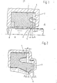
- Figure 1 shows a seal for use in the gap between a piston rod and a female housing.
- the seal consists of a rubber-elastic material and has an essentially rectangular profile, which is expanded in the direction of the medium to be sealed on the outside by a statically acting sealing lip 1, on the inside by a dynamically acting sealing lip 3.
- the statically acting sealing lip lies with a circumferential sealing edge 4 under an elastic pretension on the axially extending boundary surface of the groove, the dynamically acting sealing edge 5 under an elastic pretension on the piston rod 9 that moves back and forth due to the operation.
- the space to be sealed is denoted by 7, and Pressure of the medium to be sealed simultaneously causes the static and the dynamically acting sealing lip to be pressed against the associated one during the working cycle Machine parts.
- the function according to FIG. 2 corresponds to the function described above, but the sealing edge 5 of the dynamically acting sealing lip 3 projects beyond the sealing edge of the statically acting sealing lip 1 in the axial direction by a positive amount.
- the axial distance of the statically acting sealing lip is greater than the axial distance of the dynamically acting sealing lip from the associated end face of the groove, which extends in the radial direction.
- FIG. 3 corresponds to that according to FIG. 1, but in this case the sealing channels 4 of the slatinch-acting sealing lip 1 protrude beyond the sealing groove 5 of the dynamically acting sealing lip 3 positive measure.
- the tilting movement which can be troublesome in particular in tandem arrangements, is thereby promoted.
- the annular space enclosed between the two sealing lips and the associated, stepped end face of the groove is in direct connection with the sealed space 7 by a groove 6 extending in the radial direction.
- a pressure reduction therefore has a direct effect on the annular space, which causes the sealing edge to be lifted off 5 also favored by the surface of the piston rod, not shown, when the direction is reversed.
- the axial distance B of the statically acting sealing lip from the associated end wall area is also greater in this case than the axial distance C of the dynamically acting sealing lip.
- the proposed functional principle can be implemented using conventional grooved rings.
Landscapes
- Engineering & Computer Science (AREA)
- General Engineering & Computer Science (AREA)
- Mechanical Engineering (AREA)
- Sealing Devices (AREA)
- Sealing With Elastic Sealing Lips (AREA)
- Glass Compositions (AREA)
Priority Applications (1)
| Application Number | Priority Date | Filing Date | Title |
|---|---|---|---|
| AT83103853T ATE44595T1 (de) | 1982-12-08 | 1983-04-20 | Dichtung. |
Applications Claiming Priority (2)
| Application Number | Priority Date | Filing Date | Title |
|---|---|---|---|
| DE3245338A DE3245338C2 (de) | 1982-12-08 | 1982-12-08 | Dichtung |
| DE3245338 | 1982-12-08 |
Publications (3)
| Publication Number | Publication Date |
|---|---|
| EP0112959A2 true EP0112959A2 (fr) | 1984-07-11 |
| EP0112959A3 EP0112959A3 (en) | 1987-09-30 |
| EP0112959B1 EP0112959B1 (fr) | 1989-07-12 |
Family
ID=6180068
Family Applications (1)
| Application Number | Title | Priority Date | Filing Date |
|---|---|---|---|
| EP83103853A Expired EP0112959B1 (fr) | 1982-12-08 | 1983-04-20 | Joint |
Country Status (6)
| Country | Link |
|---|---|
| US (1) | US4553761A (fr) |
| EP (1) | EP0112959B1 (fr) |
| JP (1) | JPS59106764A (fr) |
| AT (1) | ATE44595T1 (fr) |
| BR (1) | BR8303678A (fr) |
| DE (2) | DE3245338C2 (fr) |
Cited By (3)
| Publication number | Priority date | Publication date | Assignee | Title |
|---|---|---|---|---|
| EP0136057A3 (fr) * | 1983-09-01 | 1986-04-16 | J.H. Fenner & Co. Limited | Dispositif d'étanchéité pour tige soupape |
| EP0980982A1 (fr) * | 1998-08-19 | 2000-02-23 | Ab Rexroth Mecman | Système d'étanchéité |
| ITRE20080069A1 (it) * | 2008-07-22 | 2010-01-23 | Annovi Reverberi Spa | '' gruppo pompante per pompe a pistoni per idropulitrici '' |
Families Citing this family (33)
| Publication number | Priority date | Publication date | Assignee | Title |
|---|---|---|---|---|
| DE3723654A1 (de) * | 1987-07-17 | 1989-01-26 | Stabilus Gmbh | Schwimmend angeordneter dichtring mit ventilfunktion |
| JPH0180867U (fr) * | 1987-11-19 | 1989-05-30 | ||
| US5113991A (en) * | 1988-04-26 | 1992-05-19 | Kabushiki Kaisha Daikin Seisakusho | Release device for a clutch |
| DE3990401T1 (de) * | 1988-04-26 | 1990-06-07 | Daikin Mfg Co Ltd | Ausrueckmechanismus fuer eine kupplung |
| US4884467A (en) * | 1988-12-05 | 1989-12-05 | Babcock Industries Inc. | Cable control with seal |
| US5018752A (en) * | 1990-04-19 | 1991-05-28 | Hoover Group, Inc. | Shaft seal |
| EP0563439B1 (fr) * | 1992-03-31 | 1996-01-03 | Firma Carl Freudenberg | Joint d'étanchéité pour tige coulissante |
| DE4305891C2 (de) * | 1993-02-26 | 1995-11-02 | Hecker Werke Gmbh & Co Kg Spez | Dichtung für translatorisch bewegte Teile |
| DE4335788A1 (de) * | 1993-10-20 | 1995-04-27 | Busak & Luyken Gmbh & Co | Dichtungsanordnung |
| US5509670A (en) * | 1994-10-28 | 1996-04-23 | The Texacone Company | Packing member with reduced friction |
| DE19520680C2 (de) * | 1995-02-02 | 2001-12-06 | Continental Teves Ag & Co Ohg | Hydraulisches Aggregat |
| DE19614385A1 (de) * | 1996-03-04 | 1997-09-11 | Schaeffler Waelzlager Kg | Dichtung für einen Ringkolben einer hydraulischen Kupplungs-Ausrückvorrichtung |
| DE19627617C2 (de) * | 1996-07-09 | 2001-02-08 | Mannesmann Sachs Ag | Nehmerzylinder zur hydraulischen Betätigung einer Kraftfahrzeugkupplung |
| FI970623L (fi) * | 1997-02-14 | 1998-08-15 | Valmet Corp | Aksiaalitiiviste pyörivää elintä, etenkin akselia tai vastaavaa varten |
| US6290235B1 (en) | 1997-07-02 | 2001-09-18 | Parker-Hannifin Corporation | Sealing system for a reciprocating shaft |
| US6189894B1 (en) * | 1999-04-19 | 2001-02-20 | The Texacone Company | Urethane packing member with improved geometric configuration |
| US6302402B1 (en) | 1999-07-07 | 2001-10-16 | Air Products And Chemicals, Inc. | Compliant high temperature seals for dissimilar materials |
| US6595524B1 (en) | 2000-09-25 | 2003-07-22 | Macrotech Polyseal, Inc. | Pressure regulating buffer seal |
| US6905124B2 (en) * | 2001-08-15 | 2005-06-14 | Trostel Ltd. | Unitized seal for a gas spring |
| US20050167928A1 (en) * | 2004-02-04 | 2005-08-04 | Park Edward H. | Dynamic seal using vulcanization of fluorocarbon elastomers |
| US7658387B2 (en) | 2005-06-27 | 2010-02-09 | Freudenberg-Nok General Partnership | Reinforced elastomeric seal |
| US20070004865A1 (en) | 2005-06-29 | 2007-01-04 | Freudenberg-Nok General Partnership | Dynamic vulcanization of fluorocarbon elastomers containing peroxide cure sites |
| RU2319878C1 (ru) * | 2006-08-09 | 2008-03-20 | Открытое акционерное общество "Беларусьрезинотехника" | Манжета комбинированная |
| US8840115B2 (en) * | 2007-03-09 | 2014-09-23 | Freudenberg-Nok General Partnership | Wide range temperature and pressure hydraulic cylinder sealing system |
| JP5327703B2 (ja) * | 2009-01-16 | 2013-10-30 | Nok株式会社 | ロールバックシール |
| ITVR20110171A1 (it) * | 2011-08-22 | 2013-02-23 | Alberto Bordignon | Molla a fluido |
| US9309974B1 (en) * | 2012-02-23 | 2016-04-12 | PSI-Polymer Systems, Inc. | Seals for use with low to medium viscosity fluids and related methods, apparatuses and systems |
| CN114857269A (zh) * | 2014-03-21 | 2022-08-05 | 美国圣戈班性能塑料公司 | 旋转轴密封件 |
| CN106104110B (zh) | 2014-03-27 | 2018-07-24 | 美国圣戈班性能塑料公司 | 旋转轴外壳和密封件 |
| CN104633127A (zh) * | 2014-12-29 | 2015-05-20 | 东莞市科雷明斯密封科技有限公司 | 一种反应釜用密封圈 |
| US11148649B2 (en) * | 2016-10-04 | 2021-10-19 | Hitachi Astemo, Ltd. | Master cylinder |
| US10943808B2 (en) * | 2016-11-25 | 2021-03-09 | Applied Materials, Inc. | Ceramic electrostatic chuck having a V-shape seal band |
| CN114364906B (zh) * | 2019-10-21 | 2024-10-22 | Nok株式会社 | 密封垫 |
Family Cites Families (11)
| Publication number | Priority date | Publication date | Assignee | Title |
|---|---|---|---|---|
| GB860090A (en) * | 1956-05-07 | 1961-02-01 | Renault | Improvements in and relating to sealing means |
| US3384382A (en) * | 1965-09-21 | 1968-05-21 | Nordberg Manufacturing Co | Flexible and circumferential seal for rotating shafts and the like |
| DE1970813U (de) * | 1967-08-10 | 1967-10-19 | Kugelfischer G Schaefer & Co | Nutringmanschette fuer hydraulikkolben. |
| US3527507A (en) * | 1968-02-12 | 1970-09-08 | Garlock Inc | Unitary bearing element with improved,integral scraper-sealing lip |
| US3594012A (en) * | 1969-06-17 | 1971-07-20 | Greene Tweed & Co Inc | Sealing device |
| US3655204A (en) * | 1970-02-03 | 1972-04-11 | Ato Inc | Rod wiper |
| US3854737A (en) * | 1974-01-21 | 1974-12-17 | Chemprene | Combination rotary and reciprocating unitary sealing mechanism |
| JPS598036Y2 (ja) * | 1977-08-20 | 1984-03-12 | トキコ株式会社 | シリンダ装置 |
| DE3016231C2 (de) * | 1980-04-26 | 1983-05-05 | Kaco Gmbh + Co, 7100 Heilbronn | Dichtungsanordnung |
| DE3068732D1 (en) * | 1980-11-26 | 1984-08-30 | Freudenberg Carl Fa | Sealing for rods or pistons |
| DE8225484U1 (de) * | 1982-09-10 | 1984-01-05 | Martin Merkel GmbH & Co KG, 2102 Hamburg | Abstreifring |
-
1982
- 1982-12-08 DE DE3245338A patent/DE3245338C2/de not_active Expired
-
1983
- 1983-04-20 AT AT83103853T patent/ATE44595T1/de active
- 1983-04-20 DE DE8383103853T patent/DE3380182D1/de not_active Expired
- 1983-04-20 EP EP83103853A patent/EP0112959B1/fr not_active Expired
- 1983-07-08 BR BR8303678A patent/BR8303678A/pt not_active IP Right Cessation
- 1983-09-01 US US06/528,512 patent/US4553761A/en not_active Expired - Lifetime
- 1983-11-01 JP JP58203788A patent/JPS59106764A/ja active Pending
Cited By (3)
| Publication number | Priority date | Publication date | Assignee | Title |
|---|---|---|---|---|
| EP0136057A3 (fr) * | 1983-09-01 | 1986-04-16 | J.H. Fenner & Co. Limited | Dispositif d'étanchéité pour tige soupape |
| EP0980982A1 (fr) * | 1998-08-19 | 2000-02-23 | Ab Rexroth Mecman | Système d'étanchéité |
| ITRE20080069A1 (it) * | 2008-07-22 | 2010-01-23 | Annovi Reverberi Spa | '' gruppo pompante per pompe a pistoni per idropulitrici '' |
Also Published As
| Publication number | Publication date |
|---|---|
| DE3380182D1 (en) | 1989-08-17 |
| ATE44595T1 (de) | 1989-07-15 |
| EP0112959A3 (en) | 1987-09-30 |
| DE3245338C2 (de) | 1985-10-31 |
| DE3245338A1 (de) | 1984-06-20 |
| JPS59106764A (ja) | 1984-06-20 |
| US4553761A (en) | 1985-11-19 |
| BR8303678A (pt) | 1984-11-06 |
| EP0112959B1 (fr) | 1989-07-12 |
Similar Documents
| Publication | Publication Date | Title |
|---|---|---|
| DE3245338C2 (de) | Dichtung | |
| DE69836904T2 (de) | Unidirektionale stangendichtung für einen hydraulischen zylinder | |
| DE3026877C2 (de) | Reibungsarme Dichtung | |
| DE3405351C2 (de) | Hochdruckdichtung | |
| EP0069199B1 (fr) | Vérin à fluide | |
| DE3225906A1 (de) | Dichtung fuer hydraulische kolben oder kolbenstangen | |
| DE4007252A1 (de) | Dichtungsanordnung fuer einen kompressorkolben | |
| DE4032921C2 (de) | Hochleistungsgasdruckfeder | |
| DE3446974A1 (de) | Pneumatic-zylinderbaugruppe mit einem verriegelungsmechanismus | |
| DE2937459B2 (de) | Dichtungsanordnung für eine Kolbenpumpe | |
| DE3606886C2 (de) | Dichtung für hydraulische Kolben und Kolbenstangen | |
| DE10253901A1 (de) | Mittels Drehmaschine gedrehte Stirnflächendichtung und Verfahren zum Abdichten eines irregulär geformten Hohlraumes | |
| DE3319729C2 (de) | Kolbenringanordnung für Hydraulikanwendungen, insbesondere für sehr hohe Betriebsdrücke | |
| EP3875807A1 (fr) | Agencement de segment de piston, compresseur à piston ainsi que procédé d'étanchéification d'un espace de compression | |
| DE60130489T2 (de) | Hochdruckdichtung | |
| DE3034692C2 (de) | Dichtring für einen Kolben oder eine Kolbenstange | |
| EP0052689A1 (fr) | Joint d'étanchéité pour tiges ou pistons | |
| DE3782568T2 (de) | Dichtungsanordnung verwendbar bei hochdruckgas. | |
| EP0300351A1 (fr) | Ressort pneumatique ayant une garniture d'étanchéité dépendant de la pression intérieure avec des lèvres précontraintes par gaz sous pression | |
| EP0152938A2 (fr) | Joint d'étanchéité pour piston ou tige de piston | |
| DE2329504A1 (de) | Dichtung fuer zylinder und im zylinder hin- und herbeweglichen kolben | |
| DE3505761C1 (de) | Grubenstempel-Dichtungsanordnung | |
| DE19906733A1 (de) | Dichtungssystem für Kolben-Zylinder-Einheiten | |
| DE4305891A1 (de) | Dichtung für translatorisch bewegte Teile | |
| EP0830221B1 (fr) | Unite hydraulique multiplicatrice de pression, notamment pour une presse fonctionnant selon le procede d'extrusion a haute pression interieure |
Legal Events
| Date | Code | Title | Description |
|---|---|---|---|
| PUAI | Public reference made under article 153(3) epc to a published international application that has entered the european phase |
Free format text: ORIGINAL CODE: 0009012 |
|
| AK | Designated contracting states |
Designated state(s): AT BE CH DE FR GB IT LI LU NL SE |
|
| PUAL | Search report despatched |
Free format text: ORIGINAL CODE: 0009013 |
|
| AK | Designated contracting states |
Kind code of ref document: A3 Designated state(s): AT BE CH DE FR GB IT LI LU NL SE |
|
| 17P | Request for examination filed |
Effective date: 19870825 |
|
| 17Q | First examination report despatched |
Effective date: 19880729 |
|
| ITF | It: translation for a ep patent filed | ||
| GRAA | (expected) grant |
Free format text: ORIGINAL CODE: 0009210 |
|
| AK | Designated contracting states |
Kind code of ref document: B1 Designated state(s): AT BE CH DE FR GB IT LI LU NL SE |
|
| REF | Corresponds to: |
Ref document number: 44595 Country of ref document: AT Date of ref document: 19890715 Kind code of ref document: T |
|
| GBT | Gb: translation of ep patent filed (gb section 77(6)(a)/1977) | ||
| REF | Corresponds to: |
Ref document number: 3380182 Country of ref document: DE Date of ref document: 19890817 |
|
| ET | Fr: translation filed | ||
| PLBE | No opposition filed within time limit |
Free format text: ORIGINAL CODE: 0009261 |
|
| STAA | Information on the status of an ep patent application or granted ep patent |
Free format text: STATUS: NO OPPOSITION FILED WITHIN TIME LIMIT |
|
| 26N | No opposition filed | ||
| ITTA | It: last paid annual fee | ||
| EPTA | Lu: last paid annual fee | ||
| EAL | Se: european patent in force in sweden |
Ref document number: 83103853.4 |
|
| PGFP | Annual fee paid to national office [announced via postgrant information from national office to epo] |
Ref country code: GB Payment date: 20000323 Year of fee payment: 18 |
|
| PGFP | Annual fee paid to national office [announced via postgrant information from national office to epo] |
Ref country code: DE Payment date: 20000404 Year of fee payment: 18 |
|
| PGFP | Annual fee paid to national office [announced via postgrant information from national office to epo] |
Ref country code: FR Payment date: 20000417 Year of fee payment: 18 |
|
| PGFP | Annual fee paid to national office [announced via postgrant information from national office to epo] |
Ref country code: BE Payment date: 20000418 Year of fee payment: 18 |
|
| PGFP | Annual fee paid to national office [announced via postgrant information from national office to epo] |
Ref country code: SE Payment date: 20000420 Year of fee payment: 18 Ref country code: AT Payment date: 20000420 Year of fee payment: 18 |
|
| PGFP | Annual fee paid to national office [announced via postgrant information from national office to epo] |
Ref country code: LU Payment date: 20000421 Year of fee payment: 18 |
|
| PGFP | Annual fee paid to national office [announced via postgrant information from national office to epo] |
Ref country code: NL Payment date: 20000425 Year of fee payment: 18 Ref country code: CH Payment date: 20000425 Year of fee payment: 18 |
|
| PG25 | Lapsed in a contracting state [announced via postgrant information from national office to epo] |
Ref country code: LU Free format text: LAPSE BECAUSE OF NON-PAYMENT OF DUE FEES Effective date: 20010420 Ref country code: GB Free format text: LAPSE BECAUSE OF NON-PAYMENT OF DUE FEES Effective date: 20010420 Ref country code: AT Free format text: LAPSE BECAUSE OF NON-PAYMENT OF DUE FEES Effective date: 20010420 |
|
| PG25 | Lapsed in a contracting state [announced via postgrant information from national office to epo] |
Ref country code: SE Free format text: LAPSE BECAUSE OF NON-PAYMENT OF DUE FEES Effective date: 20010421 |
|
| PG25 | Lapsed in a contracting state [announced via postgrant information from national office to epo] |
Ref country code: FR Free format text: THE PATENT HAS BEEN ANNULLED BY A DECISION OF A NATIONAL AUTHORITY Effective date: 20010430 Ref country code: BE Free format text: LAPSE BECAUSE OF NON-PAYMENT OF DUE FEES Effective date: 20010430 |
|
| PG25 | Lapsed in a contracting state [announced via postgrant information from national office to epo] |
Ref country code: LI Free format text: LAPSE BECAUSE OF NON-PAYMENT OF DUE FEES Effective date: 20010519 Ref country code: CH Free format text: LAPSE BECAUSE OF NON-PAYMENT OF DUE FEES Effective date: 20010519 |
|
| BERE | Be: lapsed |
Owner name: FIRMA CARL FREUDENBERG Effective date: 20010430 |
|
| PG25 | Lapsed in a contracting state [announced via postgrant information from national office to epo] |
Ref country code: NL Free format text: LAPSE BECAUSE OF NON-PAYMENT OF DUE FEES Effective date: 20011101 |
|
| EUG | Se: european patent has lapsed |
Ref document number: 83103853.4 |
|
| GBPC | Gb: european patent ceased through non-payment of renewal fee |
Effective date: 20010420 |
|
| REG | Reference to a national code |
Ref country code: CH Ref legal event code: PL |
|
| NLV4 | Nl: lapsed or anulled due to non-payment of the annual fee |
Effective date: 20011101 |
|
| PG25 | Lapsed in a contracting state [announced via postgrant information from national office to epo] |
Ref country code: DE Free format text: LAPSE BECAUSE OF NON-PAYMENT OF DUE FEES Effective date: 20020201 |
|
| REG | Reference to a national code |
Ref country code: FR Ref legal event code: ST |