EP0113031B1 - Dispositif de contôle de la pureté de corps moulés en métal noble - Google Patents
Dispositif de contôle de la pureté de corps moulés en métal noble Download PDFInfo
- Publication number
- EP0113031B1 EP0113031B1 EP83111752A EP83111752A EP0113031B1 EP 0113031 B1 EP0113031 B1 EP 0113031B1 EP 83111752 A EP83111752 A EP 83111752A EP 83111752 A EP83111752 A EP 83111752A EP 0113031 B1 EP0113031 B1 EP 0113031B1
- Authority
- EP
- European Patent Office
- Prior art keywords
- vibration
- moulding
- noble metal
- tested
- testing
- Prior art date
- Legal status (The legal status is an assumption and is not a legal conclusion. Google has not performed a legal analysis and makes no representation as to the accuracy of the status listed.)
- Expired
Links
- 238000012360 testing method Methods 0.000 title claims abstract description 58
- 229910000510 noble metal Inorganic materials 0.000 title claims abstract description 14
- 238000000465 moulding Methods 0.000 claims abstract description 22
- 239000013013 elastic material Substances 0.000 claims description 4
- PCHJSUWPFVWCPO-UHFFFAOYSA-N gold Chemical compound [Au] PCHJSUWPFVWCPO-UHFFFAOYSA-N 0.000 description 16
- 229910052737 gold Inorganic materials 0.000 description 16
- 239000010931 gold Substances 0.000 description 16
- 239000010970 precious metal Substances 0.000 description 12
- 239000000463 material Substances 0.000 description 9
- 238000005259 measurement Methods 0.000 description 6
- WFKWXMTUELFFGS-UHFFFAOYSA-N tungsten Chemical compound [W] WFKWXMTUELFFGS-UHFFFAOYSA-N 0.000 description 5
- 229910052721 tungsten Inorganic materials 0.000 description 5
- 239000010937 tungsten Substances 0.000 description 5
- 238000000034 method Methods 0.000 description 4
- 229910052751 metal Inorganic materials 0.000 description 3
- 239000002184 metal Substances 0.000 description 3
- 239000010953 base metal Substances 0.000 description 2
- 230000005540 biological transmission Effects 0.000 description 2
- 230000006378 damage Effects 0.000 description 2
- 230000005284 excitation Effects 0.000 description 2
- 150000002739 metals Chemical class 0.000 description 2
- 230000010355 oscillation Effects 0.000 description 2
- -1 platinum metals Chemical class 0.000 description 2
- 230000008569 process Effects 0.000 description 2
- 239000004698 Polyethylene Substances 0.000 description 1
- 238000005452 bending Methods 0.000 description 1
- 230000008859 change Effects 0.000 description 1
- 239000007799 cork Substances 0.000 description 1
- 238000013016 damping Methods 0.000 description 1
- 238000013461 design Methods 0.000 description 1
- 230000001066 destructive effect Effects 0.000 description 1
- 238000005516 engineering process Methods 0.000 description 1
- 239000004744 fabric Substances 0.000 description 1
- 239000012530 fluid Substances 0.000 description 1
- 239000011521 glass Substances 0.000 description 1
- 229910001385 heavy metal Inorganic materials 0.000 description 1
- 239000000203 mixture Substances 0.000 description 1
- 230000004048 modification Effects 0.000 description 1
- 238000012986 modification Methods 0.000 description 1
- 230000035515 penetration Effects 0.000 description 1
- 230000010363 phase shift Effects 0.000 description 1
- 238000005293 physical law Methods 0.000 description 1
- 239000011295 pitch Substances 0.000 description 1
- 239000004033 plastic Substances 0.000 description 1
- 229920003023 plastic Polymers 0.000 description 1
- 229910052697 platinum Inorganic materials 0.000 description 1
- BASFCYQUMIYNBI-UHFFFAOYSA-N platinum Substances [Pt] BASFCYQUMIYNBI-UHFFFAOYSA-N 0.000 description 1
- 229920000058 polyacrylate Polymers 0.000 description 1
- 229920000573 polyethylene Polymers 0.000 description 1
- 239000011148 porous material Substances 0.000 description 1
- 230000009467 reduction Effects 0.000 description 1
- 238000000926 separation method Methods 0.000 description 1
- 229910052709 silver Inorganic materials 0.000 description 1
- 239000004332 silver Substances 0.000 description 1
- 239000000725 suspension Substances 0.000 description 1
- 238000010998 test method Methods 0.000 description 1
- 238000004154 testing of material Methods 0.000 description 1
- 238000002604 ultrasonography Methods 0.000 description 1
Images

Classifications
-
- G—PHYSICS
- G01—MEASURING; TESTING
- G01N—INVESTIGATING OR ANALYSING MATERIALS BY DETERMINING THEIR CHEMICAL OR PHYSICAL PROPERTIES
- G01N29/00—Investigating or analysing materials by the use of ultrasonic, sonic or infrasonic waves; Visualisation of the interior of objects by transmitting ultrasonic or sonic waves through the object
- G01N29/04—Analysing solids
- G01N29/12—Analysing solids by measuring frequency or resonance of acoustic waves
-
- G—PHYSICS
- G01—MEASURING; TESTING
- G01H—MEASUREMENT OF MECHANICAL VIBRATIONS OR ULTRASONIC, SONIC OR INFRASONIC WAVES
- G01H13/00—Measuring resonant frequency
-
- G—PHYSICS
- G07—CHECKING-DEVICES
- G07D—HANDLING OF COINS OR VALUABLE PAPERS, e.g. TESTING, SORTING BY DENOMINATIONS, COUNTING, DISPENSING, CHANGING OR DEPOSITING
- G07D5/00—Testing specially adapted to determine the identity or genuineness of coins, e.g. for segregating coins which are unacceptable or alien to a currency
-
- G—PHYSICS
- G01—MEASURING; TESTING
- G01N—INVESTIGATING OR ANALYSING MATERIALS BY DETERMINING THEIR CHEMICAL OR PHYSICAL PROPERTIES
- G01N2291/00—Indexing codes associated with group G01N29/00
- G01N2291/02—Indexing codes associated with the analysed material
- G01N2291/028—Material parameters
- G01N2291/02854—Length, thickness
Definitions
- the invention relates to a device for checking the authenticity of precious metal moldings, in particular of precious metal ingots and precious metal blanks, by exciting the precious metal moldings via a vibration generator with transverse vibrations and measuring the resonance frequency with the aid of a vibration sensor.
- Gold bars and gold coins are preferably to be checked for their authenticity, but the device can also be used for moldings made of other noble metals, such as silver or platinum metals.
- test devices that determine the thermal conductivity of the test specimen can only be used to a limited extent, since this measuring principle places extreme demands on the tolerances of the test specimen dimensions, so that only special types of gold bars can be checked with them.
- a device for detecting counterfeit coins is known, in which the coin is subjected to mechanical transverse waves via a loudspeaker and the resonance frequency of the coin is determined with a microphone.
- this device has the disadvantage that it is only suitable for coins and is complex and bulky due to the necessary additional devices. In addition, it does not work very precisely.
- test specimens are subjected to longitudinal vibrations, an air gap each having to be formed between the test specimen and the vibration transmitter or vibration detector.
- counterfeit gold-plated tungsten-based products should be easy to spot.
- vibration transmitters and vibration sensors are designed as piezoelectric transducers and are coupled directly to the test specimen and one or more supports are provided for the test specimen.
- test specimens of different dimensions can be examined for their composition over their entire volume without destruction and without test residues.
- Every elastic body can be excited to characteristic vibrations, whereby the forms of vibration are limited to fundamental and harmonics.
- these vibration frequencies depend on the dimensions, the modulus of elasticity E and the density p of the test specimen. Lying e.g. rod-shaped body on two cutting edges, so they can perform transverse bending vibrations if they are deflected from their rest position by an external force.
- the frequency of the fundamental vibration of a rod depends on the thickness and length of the rod, the modulus of elasticity of its material and the density of the material. Does the external force with z. B.
- the body vibrates in resonance, i.e. with maximum vibration amplitudes. If various vibrations are applied to the body, the resonance frequency can be determined, which, given known dimensions, is a characteristic variable for the material of the molded body and can be used to identify it.
- Bars or blanks are preferably mounted on a flat plate made of elastic material or on two cutting edges or three support points and excited to transverse vibrations with a piezoelectric transducer, the frequency of which is continuously variable.
- the connection can be made using a thin wire with a diameter of around 1 mm, which is lightly pressed onto the test specimen or to which the test specimen is lightly pressed.
- the vibration amplitude is also measured with a piezoelectric transducer. Their maximum value indicates the resonance frequency, from which the ratio of modulus of elasticity / density can be read for known dimensions.
- the measurement result can be compared with a table value. Fakes are easy to spot, since there is no material or material combination that has the resonance frequency of fine gold. In particular, it is possible to identify tungsten inclusions in gold, which have the same density, but differ by a factor of 5 in the modulus of elasticity.
- the support is designed as a horizontal, flat plate made of an elastic material.
- This elastic plate must be larger than the possible test specimen, which is placed on the plate and lightly pressed against a needle-shaped vibrator attached to the edge of this plate.
- materials are used which allow the vibrations of the test specimens to be of the order of a few micrometers without significant hindrance. Felt, cork, velvet, velor fabrics, rubber and foamed plastics have proven to be suitable. Coarse-pore, foamed polyethylene with very low vibration damping values has proven particularly useful.
- the thickness of the elastic platen is not critical, but it should be greater than 1 mm.
- Test specimens of any shape and weight can be tested on this elastic pad, including any kind of precious metal bars and precious metal coins.
- electronic signals are generated or processed in the device.
- a vibrating test piece can be used to build a vibrating system, the frequency-determining element of which is the resonance frequencies of the test piece.
- the total gain must be greater than 1 and the phase shift equal to 0. This is achieved by amplifying the signal of the piezoelectric vibration sensor (possibly shifted in phase) and feeding it to the piezoelectric vibration sensor.
- This resonant circuit oscillates with a resonance frequency of the test specimen (self-excitation).
- the advantages of the self-excitation measuring circuit are the simple, inexpensive electronic structure. Testing with self-excitation, however, requires certain previous knowledge of the operating personnel, since depending on the location at which the vibration sensor is placed on the test specimen, harmonics can also develop in addition to the fundamental vibration. A discrete sequence of resonance frequencies can then be measured on the same test specimen, which makes it difficult for laypersons to interpret the measurement result.
- the oscillator signal is transmitted to the test specimen by the piezoelectric vibrator.
- the vibration frequency and vibration amplitude are measured and displayed using the vibration sensor. Since with continuous variation of the frequency of the oscillator successive fundamental and harmonics are displayed in resonance, the above-mentioned interpretation problems arise for the operating personnel. For simple handling, it is therefore desirable to store only one resonance frequency of a given test specimen at a time. This is achieved in that the oscillator emits certain characteristic frequencies that can be set and called up for characteristic test specimens (manufacturer, type, size, etc.). This makes the devices more user-friendly.
- Devices can also be used to test precious metal bars, in particular gold bars, in which the supports for the test specimen are designed as cutting edges, the position of which can be changed symmetrically to the center of the test specimen by means of a spindle.
- the supports for the test specimen are designed as cutting edges, the position of which can be changed symmetrically to the center of the test specimen by means of a spindle.
- two stops are also attached to a spindle, with the vibration sensor attached to one of the stops and a vibration sensor located above the center of the test specimen on a movable lever arm.
- the cutting edges and the stops preferably consist of polyacrylates.
- Devices for testing the authenticity of coin blanks made of precious metal can also be used, in which the test specimen rests on three radially displaceable supports designed as cones and the vibration transmitter and the vibration sensor are located together next to each other on a movable lever arm above the test center.
- the measurement of the resonance frequency takes place in the antinode of the oscillation which is formed, which is located in the center or on the edge of the round blank.
- the centering of the round blank is not problematic and can be done by eye.
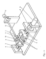
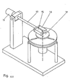
- Figures I to IV schematically show some exemplary embodiments of devices for checking the authenticity of precious metal moldings
- Figure I representing a device with a flat support plate
- Figure II a device with two cutting edges as supports
- Figure 111 a device with three tips as a support.
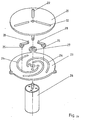
- Figure IV shows more details of the radial support shift.
- a device which can be used for bars, round blanks and other shaped bodies consists of a housing (28) into which the oscillator and the rest of the electronics are installed.
- the support (2) for receiving the test specimen (1) is designed as a flat plate and consists of an elastic material.
- the test specimen (1) is lightly pressed against the vibration transmitter (10), which is attached to the edge of the support (2) and protrudes into the air space above the support (2).
- the for commercially available shaped bodies (bars, coins) characteristic resonance frequencies can be entered into the oscillator using a keyboard (29).
- the vibration sensor (11) is removed from its holder and placed on the means of the test specimen (1).
- the maximum amplitude value of the frequency, ie the resonance frequency can be set precisely with a tuning button (30) and read off on a display window (31).
- a device is described in more detail with the aid of Figure II, with which bars of different dimensions can be tested.
- the bar In order for the basic vibration of the free bar to develop preferentially, the bar must be stored in the two nodes of the standing vibration, which according to physical laws are each 0.22 times the bar length from the center of the bar.
- the distance between the two supports (2) which have the shape of cutting edges, can be changed symmetrically to the center of the test using a spindle (5) with left and right-hand threads.
- the supports (2) are guided in bearings on two guide axes (7).
- Two stops (3, 4) which can also be moved symmetrically by a further spindle (6), are used to center the test specimen (1) with respect to the center of the distance between the two supports (2).
- Both spindles (5, 6) are driven by an actuator (8) with a reduction gear (9).
- the thread pitches of both spindles behave like 1 1.27, so that the distance between the support (2) and the stop (3 or 4) is always 0.22 x bar length.
- the stops (3, 4) are not used to clamp the test specimen (1), but as a centering aid when loading the device.
- the test specimen (1) and stops (3, 4) are separated by a fine gap so that the vibration is undamped. This gap is created by increasing the distance between the two stops (3, 4) immediately before the start of the measurement by turning the spindle (6) slightly backwards.
- the separation of the cutting edges is prevented by a freewheel on the threaded spindle (5), which only responds after the gearbox has been rotated backwards, for example by 120 °.
- the material from which the supports (2) and the stops (3, 4) are made must differ in their acoustic wave resistance of the test specimen in order to keep the transmission of vibrational energy of the ingot to the device structure as low as possible.
- the supports (2) and the stops (3, 4) are therefore preferably made of polyacrylic glass.
- the oscillation is excited laterally at a bar end by a vibration generator (10) which is mounted on a stop (4).
- Piezoelectric transducers which transmit a corresponding frequency range are suitable as vibration transmitters.
- a piezoelectric pickup is used, as is used in phono technology for scanning records. After unlocking a bar, the pickup is moved horizontally by spring force around a pivot point in the direction of the test specimen (1) in order to couple the head to the parallel bars.
- the vibration amplitude is determined in the middle of the bar by placing a lever arm (12) with a vibration sensor (11) on the test object (1).
- the lever arm (12) is provided with a counterweight (13) for adjusting the contact force.
- Any type of piezoelectric transducer is suitable for picking up vibrations.
- a piezoelectric accelerometer with a low weight is preferably used.
- the test process begins by entering the bar to be tested in an input keyboard.
- This input keyboard controls the servomotor (8) in such a way that the cutting edge distance corresponding to the respective bar type is set.
- the ingot is placed between the stops (3, 4) on the supports (2), the vibrator (10) is coupled by releasing the lock and the transducer (11) is placed on the ingot.
- the excitation frequency is varied in an interval with a frequency generator and the resonance frequency is determined. This measured value is compared with the target value, which is stored in the input unit for the corresponding bar types. In this way, any counterfeit can be recognized immediately.
- Figures 111 and IV schematically show a device for checking the authenticity of coin blanks.
- Vibration excitation and measurement of the vibration amplitude take place in the center of the test object (1).
- vibration sensor (15) and vibration sensor (16) are placed next to each other on the test object (18) on a lever arm (17).
- the contact force can be adjusted by means of a counterweight (19) on the lever arm (17).
- Piezoelectric pickups used as vibration transducers and piezoelectric vibration pickups for detecting the vibration amplitude.
- the coins are stored horizontally on three conical supports (20) which are embedded in a disk-shaped base plate (21).
- the base plate (21) contains three radially arranged elongated holes (22), each of which has an angle of 120 ° to one another.
- the supports (20) can be guided in these slots in the radial direction.
- This disc (23) contains spiral elongated holes (24) which extend from the center of the disc (23) to the edge thereof.
- a pin-like extension (25) of the supports (20) projects into each of these three spiral elongated holes (24).
- the supports (20) can be moved synchronously in the radial direction.
- coins of different diameters can be stored in the vibration node.
- the disk (23) is fixed and the base plate (21) is moved into the desired position by a stepper motor (26).
- the stepper motor (26) is mounted below both disks in the direction of the axis of rotation.
- the power is transmitted by a square nut (27) which snaps into the base plate (21).
- the functionality of the authenticity tester is demonstrated using the example of Krugerrand gold coins.
- the fundamental frequency of real coins is 9.1 kHz.
- Tungsten blanks of the same dimensions have resonance frequencies of 17.0 kHz. If tungsten blanks are coated with a gold layer of 200 ⁇ m, their resonance frequency drops to 16.1 kHz. The appearance of this coated modification is indistinguishable from real gold blanks, but the resonance frequencies are clearly separated. Further tests with blanks made of different light and heavy metals also show significant differences in the natural vibration frequencies. This demonstrates that the resonance frequency method is a meaningful authenticity check despite the relatively low expenditure on equipment.
Landscapes
- Physics & Mathematics (AREA)
- General Physics & Mathematics (AREA)
- General Health & Medical Sciences (AREA)
- Immunology (AREA)
- Life Sciences & Earth Sciences (AREA)
- Chemical & Material Sciences (AREA)
- Analytical Chemistry (AREA)
- Biochemistry (AREA)
- Acoustics & Sound (AREA)
- Health & Medical Sciences (AREA)
- Pathology (AREA)
- Investigating And Analyzing Materials By Characteristic Methods (AREA)
- Investigating Or Analyzing Materials By The Use Of Ultrasonic Waves (AREA)
- Sampling And Sample Adjustment (AREA)
- Investigating Or Analyzing Non-Biological Materials By The Use Of Chemical Means (AREA)
- Investigating Strength Of Materials By Application Of Mechanical Stress (AREA)
- Apparatuses For Generation Of Mechanical Vibrations (AREA)
Claims (4)
Priority Applications (1)
| Application Number | Priority Date | Filing Date | Title |
|---|---|---|---|
| AT83111752T ATE34232T1 (de) | 1982-12-03 | 1983-11-24 | Vorrichtung zur echtheitspruefung von edelmetallformkoerpern. |
Applications Claiming Priority (2)
| Application Number | Priority Date | Filing Date | Title |
|---|---|---|---|
| DE3244717 | 1982-12-03 | ||
| DE3244717 | 1982-12-03 |
Publications (3)
| Publication Number | Publication Date |
|---|---|
| EP0113031A2 EP0113031A2 (fr) | 1984-07-11 |
| EP0113031A3 EP0113031A3 (en) | 1985-04-10 |
| EP0113031B1 true EP0113031B1 (fr) | 1988-05-11 |
Family
ID=6179689
Family Applications (1)
| Application Number | Title | Priority Date | Filing Date |
|---|---|---|---|
| EP83111752A Expired EP0113031B1 (fr) | 1982-12-03 | 1983-11-24 | Dispositif de contôle de la pureté de corps moulés en métal noble |
Country Status (7)
| Country | Link |
|---|---|
| EP (1) | EP0113031B1 (fr) |
| JP (1) | JPS59150338A (fr) |
| AT (1) | ATE34232T1 (fr) |
| DE (1) | DE3376586D1 (fr) |
| HK (1) | HK62590A (fr) |
| IL (1) | IL70357A0 (fr) |
| ZA (1) | ZA838869B (fr) |
Families Citing this family (4)
| Publication number | Priority date | Publication date | Assignee | Title |
|---|---|---|---|---|
| DE4304170C2 (de) * | 1993-02-12 | 1995-10-19 | Isad Ingenieurbuero Gmbh Fuer | Verfahren und Vorrichtung zur Erkennung von Oberflächenstrukturen |
| DE19908620C1 (de) * | 1999-02-27 | 2000-11-30 | Degussa | Vorrichtung und Verfahren zur Echtheitsprüfung von Edelmetallformkörpern |
| GB2512289B (en) * | 2013-03-22 | 2018-12-26 | Ross Nedwell Jeremy | A device for determining the characteristic impedance spectrum of a token |
| FR3007141A1 (fr) * | 2013-06-18 | 2014-12-19 | Jacques Clausin | Dispositif de controle de la purete metallurgique des objets en or, en particulier des lingots et barres |
Family Cites Families (6)
| Publication number | Priority date | Publication date | Assignee | Title |
|---|---|---|---|---|
| AT200364B (de) * | 1957-03-06 | 1958-10-25 | Horst Dipl Ing Kottas | Einrichtung zur Messung der Resonanzfrequenzen von Probekörpern |
| GB1011472A (en) * | 1962-10-17 | 1965-12-01 | British Cast Iron Res Ass | Improvements in the non-destructive testing of materials |
| CH553456A (de) * | 1973-04-19 | 1974-08-30 | Kuniaki Miyazawa | Muenzenpruefapparat. |
| DE2628178A1 (de) * | 1976-06-23 | 1977-12-29 | Cremer & Breuer Keramische | Verfahren und vorrichtung zur automatischen, kontinuierlichen, zerstoerungsfreien qualitaetskontrolle, insbesondere von steinzeugrohren |
| DK139597B (da) * | 1977-07-01 | 1979-03-12 | Akad Tekn Videnskaber | Apparat til registrering af ekkoimpulser ved ultralydundersøgelser. |
| JPS5734545A (en) * | 1980-08-08 | 1982-02-24 | Canon Inc | Camera |
-
1983
- 1983-11-24 AT AT83111752T patent/ATE34232T1/de not_active IP Right Cessation
- 1983-11-24 DE DE8383111752T patent/DE3376586D1/de not_active Expired
- 1983-11-24 EP EP83111752A patent/EP0113031B1/fr not_active Expired
- 1983-11-28 ZA ZA838869A patent/ZA838869B/xx unknown
- 1983-12-01 IL IL70357A patent/IL70357A0/xx unknown
- 1983-12-02 JP JP58227100A patent/JPS59150338A/ja active Pending
-
1990
- 1990-08-09 HK HK625/90A patent/HK62590A/xx unknown
Non-Patent Citations (1)
| Title |
|---|
| Dtv-lexikon der Physik, Bd. 7, Seiten 80-83 * |
Also Published As
| Publication number | Publication date |
|---|---|
| DE3376586D1 (en) | 1988-06-16 |
| EP0113031A3 (en) | 1985-04-10 |
| EP0113031A2 (fr) | 1984-07-11 |
| ATE34232T1 (de) | 1988-05-15 |
| HK62590A (en) | 1990-08-17 |
| JPS59150338A (ja) | 1984-08-28 |
| ZA838869B (en) | 1984-12-24 |
| IL70357A0 (en) | 1984-03-30 |
Similar Documents
| Publication | Publication Date | Title |
|---|---|---|
| US5408882A (en) | Ultrasonic device and method for non-destructive evaluation of polymer composites | |
| EP0718596B1 (fr) | Procédé et dispositif pour la détermination dynamique de l'épaisseur et/ou du poids d'un objet en mouvement | |
| EP0336224B1 (fr) | Capteur et méthode d'examen d'émission acoustique | |
| DE3943133C2 (fr) | ||
| DE60014387T2 (de) | Verfahren und vorrichtung zur ermittlung der härte eines produkts wie zum beispiel frucht | |
| DE2844143A1 (de) | Vorrichtung zum messen der dichte einer fluessigkeit | |
| DE3045581A1 (de) | Vorrichtung zum messen der ausbreitungsgeschwindigkeit von eine sich bewegende materialbahn, insbesondere papierbahn, durchlaufenden ultraschallwellen | |
| DE2534207A1 (de) | Verfahren zum pruefen und messen von oberflaecheneigenschaften fester koerper, sowie einrichtung zur durchfuehrung des verfahrens | |
| DE2260932B2 (de) | Verfahren zum Bestimmen der Rißtiefe von in Werkstücken auftretenden Rissen | |
| DE2049550A1 (de) | Prüfeinrichtung fur Fahrzeugfederun gen | |
| EP0113031B1 (fr) | Dispositif de contôle de la pureté de corps moulés en métal noble | |
| CH422383A (de) | Schlagprüfeinrichtung | |
| DE1648738B1 (de) | Vorrichtung zur zerstoerungsfreien messung der steifigkeit von nichtmetallischen biegsamen flaechenhaften gebilden | |
| EP0763732B1 (fr) | Dispositif pour l'inspection acoustique d'articles moulés | |
| DE3628313A1 (de) | Laserinduzierte akustische erzeugung fuer schall-modul | |
| EP0099364B1 (fr) | Dispositif permettant d'effectuer des mesures micromecaniques de la surface d'objets d'essai | |
| DE2528575C3 (fr) | ||
| DE3414362A1 (de) | Verfahren zur ultraschall-pruefung von bolzen mit einem wanddickensprung | |
| DE3342418C2 (de) | Vorrichtung zur Echtheitsprüfung von Edelmetallformkörpern | |
| DE19806905C2 (de) | Einrichtung zur Bestimmung viskoelastischer Kenngrößen eines festen oder flüssigen Stoffes | |
| EP0737861B1 (fr) | Procédé et dispositif pour la détermination non-destructive des charactéristiques d'une pièce métallique | |
| EP1124125A2 (fr) | Procédé et dispositif pour détection acoustique des particules micro | |
| EP0158929B1 (fr) | Procédé de contrôle ultrasonore de goujons ayant une variation de diamètre | |
| DE69922205T2 (de) | Verfahren und vorrichtung zur oberflächenprüfung | |
| DE3814172C2 (fr) |
Legal Events
| Date | Code | Title | Description |
|---|---|---|---|
| PUAI | Public reference made under article 153(3) epc to a published international application that has entered the european phase |
Free format text: ORIGINAL CODE: 0009012 |
|
| 17P | Request for examination filed |
Effective date: 19831124 |
|
| AK | Designated contracting states |
Designated state(s): AT BE CH DE FR GB IT LI LU NL SE |
|
| PUAL | Search report despatched |
Free format text: ORIGINAL CODE: 0009013 |
|
| AK | Designated contracting states |
Designated state(s): AT BE CH DE FR GB IT LI LU NL SE |
|
| 17Q | First examination report despatched |
Effective date: 19860801 |
|
| GRAA | (expected) grant |
Free format text: ORIGINAL CODE: 0009210 |
|
| AK | Designated contracting states |
Kind code of ref document: B1 Designated state(s): AT BE CH DE FR GB IT LI LU NL SE |
|
| REF | Corresponds to: |
Ref document number: 34232 Country of ref document: AT Date of ref document: 19880515 Kind code of ref document: T |
|
| ITF | It: translation for a ep patent filed | ||
| GBT | Gb: translation of ep patent filed (gb section 77(6)(a)/1977) | ||
| REF | Corresponds to: |
Ref document number: 3376586 Country of ref document: DE Date of ref document: 19880616 |
|
| ET | Fr: translation filed | ||
| PLBE | No opposition filed within time limit |
Free format text: ORIGINAL CODE: 0009261 |
|
| STAA | Information on the status of an ep patent application or granted ep patent |
Free format text: STATUS: NO OPPOSITION FILED WITHIN TIME LIMIT |
|
| 26N | No opposition filed | ||
| ITTA | It: last paid annual fee | ||
| EPTA | Lu: last paid annual fee | ||
| EAL | Se: european patent in force in sweden |
Ref document number: 83111752.8 |
|
| PGFP | Annual fee paid to national office [announced via postgrant information from national office to epo] |
Ref country code: LU Payment date: 19951001 Year of fee payment: 13 |
|
| PGFP | Annual fee paid to national office [announced via postgrant information from national office to epo] |
Ref country code: SE Payment date: 19951011 Year of fee payment: 13 |
|
| PGFP | Annual fee paid to national office [announced via postgrant information from national office to epo] |
Ref country code: DE Payment date: 19951019 Year of fee payment: 13 |
|
| PGFP | Annual fee paid to national office [announced via postgrant information from national office to epo] |
Ref country code: BE Payment date: 19951024 Year of fee payment: 13 |
|
| PGFP | Annual fee paid to national office [announced via postgrant information from national office to epo] |
Ref country code: AT Payment date: 19951110 Year of fee payment: 13 |
|
| PGFP | Annual fee paid to national office [announced via postgrant information from national office to epo] |
Ref country code: GB Payment date: 19951115 Year of fee payment: 13 |
|
| PGFP | Annual fee paid to national office [announced via postgrant information from national office to epo] |
Ref country code: CH Payment date: 19951117 Year of fee payment: 13 |
|
| PGFP | Annual fee paid to national office [announced via postgrant information from national office to epo] |
Ref country code: NL Payment date: 19951130 Year of fee payment: 13 Ref country code: FR Payment date: 19951130 Year of fee payment: 13 |
|
| PG25 | Lapsed in a contracting state [announced via postgrant information from national office to epo] |
Ref country code: LU Free format text: LAPSE BECAUSE OF NON-PAYMENT OF DUE FEES Effective date: 19961124 Ref country code: GB Effective date: 19961124 Ref country code: AT Effective date: 19961124 |
|
| PG25 | Lapsed in a contracting state [announced via postgrant information from national office to epo] |
Ref country code: SE Effective date: 19961125 |
|
| PG25 | Lapsed in a contracting state [announced via postgrant information from national office to epo] |
Ref country code: LI Effective date: 19961130 Ref country code: CH Effective date: 19961130 Ref country code: BE Effective date: 19961130 |
|
| BERE | Be: lapsed |
Owner name: DEGUSSA A.G. Effective date: 19961130 |
|
| PG25 | Lapsed in a contracting state [announced via postgrant information from national office to epo] |
Ref country code: NL Effective date: 19970601 |
|
| REG | Reference to a national code |
Ref country code: CH Ref legal event code: PL |
|
| GBPC | Gb: european patent ceased through non-payment of renewal fee |
Effective date: 19961124 |
|
| PG25 | Lapsed in a contracting state [announced via postgrant information from national office to epo] |
Ref country code: FR Effective date: 19970731 |
|
| NLV4 | Nl: lapsed or anulled due to non-payment of the annual fee |
Effective date: 19970601 |
|
| PG25 | Lapsed in a contracting state [announced via postgrant information from national office to epo] |
Ref country code: DE Effective date: 19970801 |
|
| EUG | Se: european patent has lapsed |
Ref document number: 83111752.8 |
|
| REG | Reference to a national code |
Ref country code: FR Ref legal event code: ST |