EP0113104A2 - Vorrichtung zur Ermittlung von Bruchstellen in Energieübertragungsfasern - Google Patents
Vorrichtung zur Ermittlung von Bruchstellen in Energieübertragungsfasern Download PDFInfo
- Publication number
- EP0113104A2 EP0113104A2 EP83112920A EP83112920A EP0113104A2 EP 0113104 A2 EP0113104 A2 EP 0113104A2 EP 83112920 A EP83112920 A EP 83112920A EP 83112920 A EP83112920 A EP 83112920A EP 0113104 A2 EP0113104 A2 EP 0113104A2
- Authority
- EP
- European Patent Office
- Prior art keywords
- fiber
- power transmission
- plastic fiber
- plastic
- transmission fiber
- Prior art date
- Legal status (The legal status is an assumption and is not a legal conclusion. Google has not performed a legal analysis and makes no representation as to the accuracy of the status listed.)
- Granted
Links
Images

Classifications
-
- G—PHYSICS
- G01—MEASURING; TESTING
- G01M—TESTING STATIC OR DYNAMIC BALANCE OF MACHINES OR STRUCTURES; TESTING OF STRUCTURES OR APPARATUS, NOT OTHERWISE PROVIDED FOR
- G01M11/00—Testing of optical apparatus; Testing structures by optical methods not otherwise provided for
- G01M11/30—Testing of optical devices, constituted by fibre optics or optical waveguides
Definitions
- the present invention relates to optical power transmission fibers for use in laser knives and laser machining devices.
- a fracture (crack) in an optical power transmission fiber presents a serious problem in transmitting power through the optical fiber.
- Various conventional methods are known for detecting fractures in optical fibers.
- One such method is disclosed in Japanese Published Patent Application No. 12602/81 and Japanese Utility Model Application No. 69211/82. Both of these methods, however, use an electrical circuit that extends to the terminating end of the power transmission line. If the transmission line is used to supply power to medical equipment such as a laser knife or a machining tool that requires a high degree of electrical insulation, special provisions must be taken to insulate the terminating end of the transmission line. However, this cannot be effected without detracting from the inherently high insulating property of the optical fiber.
- the present invention provides a device for detecting fractures in optical fibers that is free from the above-described defects of the prior art.
- At least one plastic fiber is disposed parallel to and close to the power transmission fiber to be tested.
- a reference light beam is carried by the plastic fiber. If a fracture is present in the power transmission fiber, heat at a high temperature is generated in the area around the fracture site of the fiber. The plastic fiber disposed parallel to the power transmission fiber is melted by the heat in that region. By detecting an amount of the reference light beam passing through the plastic fiber, a fracture of the power transmission fiber can be detected.
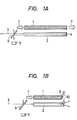
- Figs. lA and lB show the basic construction of the detecting system of the first embodiment.
- a power transmission fiber 1 and a plastic fiber 2 are laid side by side.
- a reference light beam 3 is introduced into the plastic fiber 2.
- the receiving or terminating end of the plastic fiber is provided with a reflecting coating 4 capable of efficient reflection of light at a wavelength equal to that of the reference light beam.
- the reference beam upon being reflected from the terminating end, travels back to the transmitting end where it is branched at a right angle by a half-silvered mirror 9 and received by a photodetector 5. If a fracture is present in the power transmission fiber as shown in Fig.
- the area around the fracture site 8 becomes hot, as hot as several hundred degrees Celsius, due to the presence of the fracture. If the plastic fiber has a sufficiently low melting point, for instance, about 100 degress Celsius, it will melt. As a result, the reference light beam will not be reflected and no light will be received by the detector. Therefore, by sensing the output of the detector, fractures in the power transmission fiber can readily be detected.
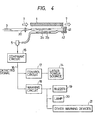
- FIG. 2 A block diagram of a detection system that embodies all the features described above, except (2), is shown in Fig. 2.
- a signal received by the detector 5 is fed to a comparator circuit 15.
- the detected signal 16 the active state of which indicates the occurrence of a fracture, is fed back to the laser power source 14 through a control circuit 18.
- the signal 16 is supplied to a warning circuit 18 that actuates a buzzer 19, lamp 20 or other suitable warning devices 21.
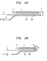
- Figs. 3A and 3B show the basic construction of a detecting system of a second embodiment.
- a fiber 1 transmitting a power beam 3 and two plastic fibers 2a and 2b are laid side by side.
- a reference beam 3 is introduced into the plastic fiber 2a.
- the receiving or terminating end of the plastic fiber is provided with a reflecting surface 5 capable of reflecting the reference beam 3.
- the reflected light 6 passes through the plastic fiber 2b and is received at a detector 7. If a fracture is present in the power transmission fiber, as shown in Fig. 3B, the area around the fracture site 8 becomes hot, as hot as several hundred degrees Celsius. Assuming that the plastic fiber has a low melting point of about 100 degrees Celsius, the fiber will melt. As a result, the reference light beam 3 will not arrive at the end and be reflected and no light will be received by the detector 5. Therefore, by sensing the output of the detector 5, open-circuit failure in the power transmission fiber 2 can be detected.
- Each of the two plastic fibers 2a and 2b may be made of a single fiber or a bundle of fibers.
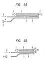
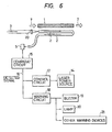
- Figs. 5A and 5B show the basic construction of the detection system of a third embodiment.
- a fiber 1 transmitting a power beam 7 and a plastic fiber 2 folded back at a point close to the receiving end of the power transmission fiber are laid side by side.
- a reference beam 3 is introduced into one end of the plastic fiber 2.
- the reflected beam 6 from the folded point of the plastic fiber is received by a photodetector 5. If a fracture occurs in . the power transmission fiber shown in Fig. 5B, the area around the site 8 becomes as hot as several hundred degrees Celsius, whereupon the low-melting-point plastic fiber is melted.
- the reference light beam is not reflected, and no light is received by the detector 5. Therefore, by sensing the output of the detector 5, the fracture in the power transmission fiber 2 can be detected.
- FIG. 6 A preferred implementation of this embodiment is shown in Fig. 6. The same modes discussed above are applicable to this embodiment, as well as the same detector system.
- an open-circuit failure in a power transmission fiber is detected by a change in the amount of the light reflected through the plastic fiber. This provides positive protection against hazards resulting from open-circuit failure.
Landscapes
- Physics & Mathematics (AREA)
- Optics & Photonics (AREA)
- Chemical & Material Sciences (AREA)
- Analytical Chemistry (AREA)
- General Physics & Mathematics (AREA)
- Investigating Or Analysing Materials By Optical Means (AREA)
- Geophysics And Detection Of Objects (AREA)
Applications Claiming Priority (6)
| Application Number | Priority Date | Filing Date | Title |
|---|---|---|---|
| JP23428782A JPS59119236A (ja) | 1982-12-24 | 1982-12-24 | パワ−伝送用フアイバの断線検知方法 |
| JP234287/82 | 1982-12-24 | ||
| JP58009055A JPS59135339A (ja) | 1983-01-22 | 1983-01-22 | パワ−伝送用フアイバの断線検知方式 |
| JP9055/83 | 1983-01-22 | ||
| JP16996083A JPS6060531A (ja) | 1983-09-13 | 1983-09-13 | パワ−伝送用フアイバの断線検知方式 |
| JP169960/83 | 1983-09-13 |
Publications (3)
| Publication Number | Publication Date |
|---|---|
| EP0113104A2 true EP0113104A2 (de) | 1984-07-11 |
| EP0113104A3 EP0113104A3 (en) | 1985-04-17 |
| EP0113104B1 EP0113104B1 (de) | 1987-07-15 |
Family
ID=27278305
Family Applications (1)
| Application Number | Title | Priority Date | Filing Date |
|---|---|---|---|
| EP19830112920 Expired EP0113104B1 (de) | 1982-12-24 | 1983-12-21 | Vorrichtung zur Ermittlung von Bruchstellen in Energieübertragungsfasern |
Country Status (4)
| Country | Link |
|---|---|
| EP (1) | EP0113104B1 (de) |
| AU (1) | AU561121B2 (de) |
| CA (1) | CA1218724A (de) |
| DE (1) | DE3372540D1 (de) |
Cited By (4)
| Publication number | Priority date | Publication date | Assignee | Title |
|---|---|---|---|---|
| DE4010789A1 (de) * | 1989-04-13 | 1990-10-18 | Gen Electric | Lichtwellenleitersicherheitssystem |
| DE102009052762A1 (de) | 2009-11-11 | 2011-05-12 | Precitec Kg | Laserbearbeitungskopf und Verfahren zur Vermeidung einer Beschädigung eines Lichtleitfaserendes |
| EP3385616A1 (de) * | 2017-04-05 | 2018-10-10 | Mafelec | Signalisierungsvorrichtung und -gerät sowie diagnose- und/oder steuerungsverfahren |
| CN112098045A (zh) * | 2020-09-10 | 2020-12-18 | 无锡科晟光子科技有限公司 | 长距离下的分布式光纤预警系统断纤检测方法 |
Family Cites Families (3)
| Publication number | Priority date | Publication date | Assignee | Title |
|---|---|---|---|---|
| FR2280072A1 (fr) * | 1974-07-26 | 1976-02-20 | Douillie Remy | Procede et equipement de mesure permettant de localiser une cassure sur un cable optique |
| FR2393287A1 (fr) * | 1977-05-31 | 1978-12-29 | Cables De Lyon Geoffroy Delore | Echometre pour la localisation de defauts affectant les conducteurs de lumiere |
| DE2739880C2 (de) * | 1977-09-05 | 1985-04-18 | Philips Kommunikations Industrie AG, 8500 Nürnberg | Vorrichtung zur Fehlerortbestimmung in Lichtleitfasern oder Lichtleitfaserkabeln |
-
1983
- 1983-12-21 EP EP19830112920 patent/EP0113104B1/de not_active Expired
- 1983-12-21 AU AU22724/83A patent/AU561121B2/en not_active Ceased
- 1983-12-21 CA CA000443878A patent/CA1218724A/en not_active Expired
- 1983-12-21 DE DE8383112920T patent/DE3372540D1/de not_active Expired
Cited By (9)
| Publication number | Priority date | Publication date | Assignee | Title |
|---|---|---|---|---|
| DE4010789A1 (de) * | 1989-04-13 | 1990-10-18 | Gen Electric | Lichtwellenleitersicherheitssystem |
| GB2232483A (en) * | 1989-04-13 | 1990-12-12 | Gen Electric | Fiber optic safety system |
| US5012087A (en) * | 1989-04-13 | 1991-04-30 | General Electric Company | Fiber optic safety system |
| DE102009052762A1 (de) | 2009-11-11 | 2011-05-12 | Precitec Kg | Laserbearbeitungskopf und Verfahren zur Vermeidung einer Beschädigung eines Lichtleitfaserendes |
| DE102009052762B4 (de) * | 2009-11-11 | 2015-03-19 | Precitec Kg | Laserbearbeitungskopf und Verfahren zur Vermeidung einer Beschädigung eines Lichtleitfaserendes |
| EP3385616A1 (de) * | 2017-04-05 | 2018-10-10 | Mafelec | Signalisierungsvorrichtung und -gerät sowie diagnose- und/oder steuerungsverfahren |
| FR3065086A1 (fr) * | 2017-04-05 | 2018-10-12 | Mafelec | Dispositif et appareil de signalisation et procede de diagnostic et/ou d'asservissement |
| CN112098045A (zh) * | 2020-09-10 | 2020-12-18 | 无锡科晟光子科技有限公司 | 长距离下的分布式光纤预警系统断纤检测方法 |
| CN112098045B (zh) * | 2020-09-10 | 2022-12-20 | 无锡科晟光子科技有限公司 | 长距离下的分布式光纤预警系统断纤检测方法 |
Also Published As
| Publication number | Publication date |
|---|---|
| EP0113104B1 (de) | 1987-07-15 |
| EP0113104A3 (en) | 1985-04-17 |
| AU2272483A (en) | 1984-06-28 |
| DE3372540D1 (en) | 1987-08-20 |
| CA1218724A (en) | 1987-03-03 |
| AU561121B2 (en) | 1987-04-30 |
Similar Documents
| Publication | Publication Date | Title |
|---|---|---|
| US5012087A (en) | Fiber optic safety system | |
| US4423726A (en) | Safety device for laser ray guide | |
| US7088437B2 (en) | Optical fibre means | |
| US5270537A (en) | Laser initiated ordance system optical fiber continuity test | |
| US5359192A (en) | Dual-wavelength low-power built-in-test for a laser-initiated ordnance system | |
| EP3934031B1 (de) | Laservorrichtung | |
| US6259517B1 (en) | Optical fiber breakage detection system | |
| WO1993026031A9 (en) | Dual-wavelength low-power built-in-test for a laser-initiated ordnance system | |
| US5159190A (en) | Radiating and receiving arrangement for a fiber-optic sensor having dual sources and detectors | |
| WO1993003881A1 (en) | Apparatus and method for monitoring laser material processing | |
| US5729012A (en) | Photoluminescence built-in-test for optical systems | |
| EP0113104A2 (de) | Vorrichtung zur Ermittlung von Bruchstellen in Energieübertragungsfasern | |
| CN111164404B (zh) | 故障检测装置、激光器加工系统以及故障检测方法 | |
| USH376H (en) | Degradation monitor for laser optics | |
| JPH05277775A (ja) | レーザ加工装置 | |
| US5130533A (en) | Device for measuring backscattered radiation using a frequency selective element | |
| EP0093005B1 (de) | Laservorrichtung | |
| JPH0151136B2 (de) | ||
| EP0113046B1 (de) | Wärmefühler | |
| JPH0825072A (ja) | レーザ溶接機用の溶接状態監視装置およびその監視方法 | |
| JPH02107939A (ja) | 光ファイバーの状態監視装置 | |
| JPS59119236A (ja) | パワ−伝送用フアイバの断線検知方法 | |
| JPH0572533B2 (de) | ||
| JPS59135339A (ja) | パワ−伝送用フアイバの断線検知方式 | |
| KR100232635B1 (ko) | 레이저 전송용 광섬유 손상 감시장치 |
Legal Events
| Date | Code | Title | Description |
|---|---|---|---|
| PUAI | Public reference made under article 153(3) epc to a published international application that has entered the european phase |
Free format text: ORIGINAL CODE: 0009012 |
|
| AK | Designated contracting states |
Designated state(s): DE FR GB SE |
|
| PUAL | Search report despatched |
Free format text: ORIGINAL CODE: 0009013 |
|
| AK | Designated contracting states |
Designated state(s): DE FR GB SE |
|
| 17P | Request for examination filed |
Effective date: 19850529 |
|
| 17Q | First examination report despatched |
Effective date: 19860415 |
|
| GRAA | (expected) grant |
Free format text: ORIGINAL CODE: 0009210 |
|
| AK | Designated contracting states |
Kind code of ref document: B1 Designated state(s): DE FR GB SE |
|
| REF | Corresponds to: |
Ref document number: 3372540 Country of ref document: DE Date of ref document: 19870820 |
|
| ET | Fr: translation filed | ||
| PLBE | No opposition filed within time limit |
Free format text: ORIGINAL CODE: 0009261 |
|
| STAA | Information on the status of an ep patent application or granted ep patent |
Free format text: STATUS: NO OPPOSITION FILED WITHIN TIME LIMIT |
|
| 26N | No opposition filed | ||
| PGFP | Annual fee paid to national office [announced via postgrant information from national office to epo] |
Ref country code: SE Payment date: 19911111 Year of fee payment: 9 |
|
| PGFP | Annual fee paid to national office [announced via postgrant information from national office to epo] |
Ref country code: FR Payment date: 19911209 Year of fee payment: 9 |
|
| PGFP | Annual fee paid to national office [announced via postgrant information from national office to epo] |
Ref country code: GB Payment date: 19911210 Year of fee payment: 9 |
|
| PGFP | Annual fee paid to national office [announced via postgrant information from national office to epo] |
Ref country code: DE Payment date: 19920131 Year of fee payment: 9 |
|
| PG25 | Lapsed in a contracting state [announced via postgrant information from national office to epo] |
Ref country code: GB Effective date: 19921221 |
|
| PG25 | Lapsed in a contracting state [announced via postgrant information from national office to epo] |
Ref country code: SE Effective date: 19921222 |
|
| GBPC | Gb: european patent ceased through non-payment of renewal fee |
Effective date: 19921221 |
|
| PG25 | Lapsed in a contracting state [announced via postgrant information from national office to epo] |
Ref country code: FR Effective date: 19930831 |
|
| PG25 | Lapsed in a contracting state [announced via postgrant information from national office to epo] |
Ref country code: DE Effective date: 19930901 |
|
| REG | Reference to a national code |
Ref country code: FR Ref legal event code: ST |
|
| EUG | Se: european patent has lapsed |
Ref document number: 83112920.0 Effective date: 19930709 |