EP0113144A2 - Pince à balles - Google Patents
Pince à balles Download PDFInfo
- Publication number
- EP0113144A2 EP0113144A2 EP83201733A EP83201733A EP0113144A2 EP 0113144 A2 EP0113144 A2 EP 0113144A2 EP 83201733 A EP83201733 A EP 83201733A EP 83201733 A EP83201733 A EP 83201733A EP 0113144 A2 EP0113144 A2 EP 0113144A2
- Authority
- EP
- European Patent Office
- Prior art keywords
- claw
- telescoping
- pick
- pack
- bales
- Prior art date
- Legal status (The legal status is an assumption and is not a legal conclusion. Google has not performed a legal analysis and makes no representation as to the accuracy of the status listed.)
- Granted
Links
- 210000000078 claw Anatomy 0.000 title claims abstract description 82
- 239000000463 material Substances 0.000 claims abstract description 6
- 235000013325 dietary fiber Nutrition 0.000 claims abstract description 5
- 230000000712 assembly Effects 0.000 claims description 12
- 238000000429 assembly Methods 0.000 claims description 12
- 239000004460 silage Substances 0.000 description 26
- 244000025254 Cannabis sativa Species 0.000 description 3
- 230000000903 blocking effect Effects 0.000 description 3
- 240000004658 Medicago sativa Species 0.000 description 1
- 235000010624 Medicago sativa Nutrition 0.000 description 1
- 230000004075 alteration Effects 0.000 description 1
- 239000002131 composite material Substances 0.000 description 1
- 238000010276 construction Methods 0.000 description 1
- 230000008878 coupling Effects 0.000 description 1
- 238000010168 coupling process Methods 0.000 description 1
- 238000005859 coupling reaction Methods 0.000 description 1
- 238000000034 method Methods 0.000 description 1
- 230000035515 penetration Effects 0.000 description 1
- 239000010902 straw Substances 0.000 description 1
- 239000000725 suspension Substances 0.000 description 1
Images




Classifications
-
- A—HUMAN NECESSITIES
- A01—AGRICULTURE; FORESTRY; ANIMAL HUSBANDRY; HUNTING; TRAPPING; FISHING
- A01D—HARVESTING; MOWING
- A01D87/00—Loaders for hay or like field crops
- A01D87/12—Loaders for sheaves, stacks or bales
- A01D87/127—Apparatus for handling, loading or unrolling round bales
-
- A—HUMAN NECESSITIES
- A01—AGRICULTURE; FORESTRY; ANIMAL HUSBANDRY; HUNTING; TRAPPING; FISHING
- A01D—HARVESTING; MOWING
- A01D87/00—Loaders for hay or like field crops
- A01D87/12—Loaders for sheaves, stacks or bales
- A01D87/126—Loaders for stacks or groups of bales
Definitions
- the invention relates to a pick-up claw apparatus connectible to a farm truck for handling a baled material, in particular baled roughage, comprising a carrier beam which, when the apparatus is coupled to the truck, is at right angles to the direction of travel of the vehicle, and which carrier beam is connected to one or more hydraulically operated claw members.
- Such an apparatus is known from "Landbouwmechani- satie" 32 (1981) 12 (December) and is employed in the embodiment of a so-called three-pack claw apparatus besides a so-called large baling press, which is destined for pressing pre-dried grass, hay, lucerne, straw and other products to be pressed to large bales.
- the bales obtained with the large baling press have dimensions of 1.60 x 1.20 x 0.70 m and are kept together by a number of (mostly four) binding wires secured about the bales, at right angles to the longitudinal direction thereof, by means of provisions made on the large baling press.
- the bales are found in practice not to have the form of a regular rectangle, but the bale leaving the large baling press has a concave top and a convex bottom.
- the cause of this phenomenon seems to reside in the fact that the material to be pressed, which is present in the pressing channel, as regards height, has an unequal stacking density in the sense that the lower zone has a larger density than the upper zone.
- the binding wires are wound loosely about the bale when under squeeze pressure. When the squeeze pressure is removed, the bale expands as the pressed material springs back, settling around and against the binding wires. The spring-back takes place more strongly in the lower portion of the bale owing to the larger quantity of material available at that location due to the larger stacking density, with the above result of the bale form.
- the carrier beam is a single, non-composite beam and can carry up to three claw members attached thereto, i.e., seen in the direction of travel of the farm truck, such as a lift truck, wheel loader or mechanical shovel, one in the centre at the front of the longitudinal side of the beam, and the other two at the ends thereof.
- the pick-up claw members each have a number of pointed analogously formed claws (e.g. three), which claw members and hence the respective claws are hydraulically movable up and down in the vertical plane.
- the hydraulic operation of the pick-up claw apparatus, and of the claw members, respectively, takes place by means of the hydraulic system of the truck.
- the direct drive means for the claw members, such as the hydrocylinders, are also carried by the carrier beam.
- the known three-pack claw apparatus picks up three bales at a time, loading the same e.g. on a waggon, mostly a flat open waggon, from the sides, for the bales to be transported further e.g. to the silage location.
- the three bales to be picked up are placed on the ground in a pack with the sides of 1.20 m in co-extensive relationship. During the pick-up, first the central bale is seized and then the two outer bales, while the claws connected to the ends of the carrier beam are driven into the end faces of the pack, while exerting a compressive force in longitudinal direction of the pack.
- the loading of the waggon with the three bales picked up by the three-pack claw apparatus then takes place in such a manner that the longitudinal direction of the pack is parallel to the longitudinal direction of the waggon, i.e., so that the dimension of 1.60 m is transverse to the longitudinal direction of the waggon.
- the transverse dimension of the waggon is normally chosen in such a way that the packs can be stacked in two rows, side by side, in the longitudinal direction of the truck.
- the total width of the load on the truck is therefore 3.20 m.
- the transport of such a wide load through the built-up area of a town or village is legally not permitted without anything more.
- the prior pick-up claw apparatus stacks the packs at the silage location in such a manner that the faces of the bales having the sizes 1.60 x 1.20 m form the bearing surface of the stack and the dimension of 0.70 m is directed vertically.
- the stacking of the packs at the silage location takes place in such a manner that, working from the end of the silage stack to be formed, there is obtained an eventual silage stack having a form that can be described as an elongated parallelepiped of substantially rectangular cross-section, the packs being deposited with the dimension of 1.60 m in the longitudinal direction of the eventuel silage stack and hence the dimension of 1.20 m of each of the three bales in co-extensive relationship and consequently transverse to the longitudinal direction of the eventuel silage stack.
- This stacking method results in that the bales which, stacked onto each other, form the vertical longitudinal side faces of the silage stack, have the tendency to fall over outwardly, since the rounded form of each of the separate bales, resulting from the binding together of the bales by means of the binding wires, extends in that direction.
- the packs should be stackable in such a manner that, while preserving the bearing surface, as regards each bale, the rounded form of the bales extends from the side face having the dimensions 1.60 x 1.20 m, in the transverse direction of the eventual silage stack to be formed, while the contemplated pick-up claw apparatus should be capable of picking up packs of different widths, so that this can be used in a more universal manner.
- the above objects are achieved by providing a pick-up claw apparatus of the above described type, which is characterized in that the claw members are connected to the carrier beam in parallel and laterally reciprocable relationship, in a direction at right angles to the beam.
- the apparatus provided at least with three claw members, it is further characterized in that, for the lateral movability relative to each other, the claw members are connected to a carrier beam consisting of one or more telescoping beam assemblies.
- a pick-up claw apparatus enables to pick up all at once up to 3 bales of the roughage, such as pre-dried grass etc., united to one pack with the sides of 1.60 m in co-extensive relationship, i.e., with a total pack length of 4.80 m.
- Such a load width complies with the statutory standard and a truck thus loaded can also be driven conveniently through the built-up area of a town or village.
- the same pick-up claw apparatus according to the invention also allows to handle smaller packs, e.g. formed from only two bales or even a single bale, as will be explained in the following.
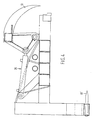
- the claw member which, as is known per se, when the apparatus is coupled to the farm truck, comprises a curved member movable up and down in the vertical plane, is designed as a combination of the curved member as an upper claw portion and a coacting lower claw portion, while preferably the lower claw portion coacting with the upper portion is substantially straight and immovable, and consequently is an impaler.
- the line of movement and the position of the upper claw portion relative to the lower portion will be chosen in such a manner that the pack to be picked up by the pick-up claw apparatus is subjected to an upward and, seen in the direction of travel, rearward movement, with the upper claw portions biting into the top face of the respective bales.
- the claws do not project beyond the pack, so that the packs can also be placed against a wall or can even be put away in a corner, e.g. of a shed.
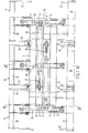
- 1 indicates a three-pack pick-up claw apparatus with carrier beam 2, being an assembly of two pairs of telescoping box beam assemblies 3, 3' and 4,4'.
- the telescoping box beam assemblies, pertaining to the pair 3, 3', comprise outer beams 5, 5' and inner beams 6, 6', while the pair 4, 4'comprise outer beams 7,7' and inner beams 8, 8!.
- a carrier frame 9 is welded onto the ends of the outwardly and inwardly telescoping inner beams 6, 6-'of the beam assemblies 3, 3', two frame beams 18 and 21 forming part of said carrier frame.
- the ends of the frame beam 18 are connected to upper claws 12 and 15 and the ends of the frame beam 21 to lower claws 12' and 15'.
- the carrier frame 9 furthermore carries a hydrocylinder-and-piston assembly 24, which is disposed on the carrier frame 9 in such a manner that the frame beam 18 can be rotated thereby and hence the upper claws 12, 15 can be moved up and down in the vertical plane, thereby coacting with the fixed, tooth-shaped lower claws 12', 15' for the purpose of gripping or disengaging the bale-shaped load.
- the position of the coacting upper and lower claws 12, 12' and 15, 15', with their attachment to the carrier frame 9, is chosen in such a manner that, when the bale-shaped load is gripped, a rearward and upward movement is imparted thereto.
- the carrier frame 11 is further fitted with the hydrocylinder-and-piston assembly 25 with which, eventually, the upper claws 14 and 17 are again synchronously movable up and down in the vertical plane.
- a third carrier frame 10 which, however, is affixed to the outer beams 5, 5', 7, 7' and hence is immovable and stationary.
- the fixed frame 10 is provided with frame beams 19, 22; upper claws 13, 16, and fixed tooth-shaped lower claws 13', 16' movable in the vertical plane, as well as a hydrocylinder-and-piston assembly 26.
- the telescoping beam assemblies 3, 3'coacting for the outward and inward movement of the carrier frame 9 with the upper claws 12, 15 and lower claws 12', 15' are provided with a blocking element 27, not further described, for limiting the telescoping movement of the inner beams.
- the telescoping beam assemblies 4, 4' are provided with a blocking element 28.
- the telescoping movement of the inner beams 6, 6', and 8, 8', respectively, takes place by means of the hydrocylinder-and-piston assembly 29, 30.
- the three-pack pick-up claw 1 is further fitted with coupling means, not further shown, by means of which it can be coupled e.g. to a wheel loader, and with connection means through which the hydraulic system of the three-pack pick-up claw 1 can be connected to the hydraulic system of the wheel loader.
- the three-pack pick-up claw can be operated as follows.
- the bales of dimensions 1.60 x 1.20 x 0.70 m kept together by binding wires 36 and formed by means of a so-called large baling press during the gathering of e.g. pre-dried silage grass are installed side by side in groups of three bales 31, 32, 33 (Fig. 6) and formed into one pack.
- the precise width of the carrier beam is adjusted by moving the inner beams 6, 6' and 8, 8' outwardly up to the maximally extended position.
- the pick-up claw apparatus is transported in the direction of the pack, the lower claws are inserted in the pack and the pack is further gripped by the downward movement of the upper claws and the penetration of said claws in the top face of the bales.
- the pack is compressed in the direction of the arrows A (Fig. 6), in which condition the pack can be conveniently lifted and transported to a truck.
- the three bales can also be formed to a pack, as now conventional in the art in question, and as shown in Fig. 7.
- the inner beams 6, 6' and 8, 8' will then be moved outwardly a smaller distance, determined by adjustment of the blocking elements 27, 28.
- the three-pack pick-up claw apparatus also permits handling packs that consist of two bales 34, 35, as shown in Figs. 8, 9.
Landscapes
- Life Sciences & Earth Sciences (AREA)
- Environmental Sciences (AREA)
- Loading Or Unloading Of Vehicles (AREA)
- Storage Of Harvested Produce (AREA)
Applications Claiming Priority (2)
| Application Number | Priority Date | Filing Date | Title |
|---|---|---|---|
| NL8204742A NL8204742A (nl) | 1982-12-07 | 1982-12-07 | Balenoppakklauwinrichting. |
| NL8204742 | 1982-12-07 |
Publications (3)
| Publication Number | Publication Date |
|---|---|
| EP0113144A2 true EP0113144A2 (fr) | 1984-07-11 |
| EP0113144A3 EP0113144A3 (en) | 1984-08-15 |
| EP0113144B1 EP0113144B1 (fr) | 1988-10-26 |
Family
ID=19840712
Family Applications (1)
| Application Number | Title | Priority Date | Filing Date |
|---|---|---|---|
| EP83201733A Expired EP0113144B1 (fr) | 1982-12-07 | 1983-12-07 | Pince à balles |
Country Status (4)
| Country | Link |
|---|---|
| US (1) | US4548535A (fr) |
| EP (1) | EP0113144B1 (fr) |
| DE (1) | DE3378295D1 (fr) |
| NL (1) | NL8204742A (fr) |
Cited By (3)
| Publication number | Priority date | Publication date | Assignee | Title |
|---|---|---|---|---|
| EP0317671A1 (fr) * | 1987-11-26 | 1989-05-31 | Ford New Holland N.V. | Appareil modulaire pour la manipulation des balles |
| EP0317670A1 (fr) * | 1987-11-27 | 1989-05-31 | Ford New Holland N.V. | Appareil pour la manipulation des balles avec plusieurs ramasseurs de balles |
| NL1012446C2 (nl) * | 1999-06-25 | 2000-12-28 | Schuitemaker Mach Bv | Kleminrichting voor het oppakken van balen zoals graspakken. |
Families Citing this family (10)
| Publication number | Priority date | Publication date | Assignee | Title |
|---|---|---|---|---|
| US4911491A (en) * | 1987-11-26 | 1990-03-27 | Ford New Holland, Inc. | Modular bale handling apparatus with plurality of bale pick-up devices |
| US5829940A (en) * | 1997-03-17 | 1998-11-03 | Soo Tractor Sweeprake Company | Bale handler attachment and bale stacking method |
| US6328520B1 (en) | 1998-08-10 | 2001-12-11 | Thomas B. Maclay | Vehicle mounted large bale loading, transporting and unloading system |
| AU755579B2 (en) | 1999-11-22 | 2002-12-19 | Thomas B. Maclay | Loading grapple table |
| CA2479962C (fr) | 2002-03-22 | 2008-12-02 | Thomas B. Maclay | Plate-forme de ramassage et d'alimentation montee sur un vehicule |
| RU2225690C2 (ru) * | 2002-06-11 | 2004-03-20 | Глухарев Владимир Алексеевич | Грузозахватное устройство |
| US6817820B2 (en) * | 2002-08-21 | 2004-11-16 | Triple C Manufacturing, Inc. | Square bale feeder attachment for flat-bed vehicles |
| FR2873536B1 (fr) * | 2004-08-02 | 2006-09-29 | Julien Combret | Fourche de manutention, permettant le maintien au retournement des bottes cubiques |
| US20110002757A1 (en) * | 2009-07-01 | 2011-01-06 | Steven Mark Taylor | Hay bale grabber farm implement |
| WO2012166551A2 (fr) | 2011-05-31 | 2012-12-06 | Price Edward B | Accessoire preneur pour machine motrice |
Family Cites Families (13)
| Publication number | Priority date | Publication date | Assignee | Title |
|---|---|---|---|---|
| US2734646A (en) * | 1956-02-14 | Hay loader | ||
| US2587769A (en) * | 1948-04-05 | 1952-03-04 | Rowe Warehouse & Fertilizer Co | Bale stacking and unstacking machine |
| US3112136A (en) * | 1959-03-23 | 1963-11-26 | Gerald T Hammond | Article grouping and stacking apparatus |
| US3052366A (en) * | 1960-04-18 | 1962-09-04 | Wilber O Duncan | Power operated bale pilers |
| FR1493537A (fr) * | 1966-06-03 | 1967-09-01 | Mills Const Sa | Palonnier pour la manutention de pièces de dimensions diverses |
| US3420564A (en) * | 1966-08-12 | 1969-01-07 | Doyne A Jensen | Hay bale loader and stacker attachment |
| US3333322A (en) * | 1966-09-29 | 1967-08-01 | Norman R Toffolon | Method of erecting prefabricated panels and the like |
| BE717157A (fr) * | 1968-06-26 | 1968-12-02 | ||
| US3876093A (en) * | 1973-03-09 | 1975-04-08 | Pettibone Corp | Bale handler |
| GB1554183A (en) * | 1974-12-21 | 1979-10-17 | Donnerfield Ltd | Bale handling apparatus |
| SU640699A1 (ru) * | 1977-06-27 | 1979-01-05 | Головное Специализированное Конструкторское Бюро По Сеноуборочной Технике | Погрузчик |
| GB1603621A (en) * | 1978-05-04 | 1981-11-25 | Sanderson R | Load handling and moving device |
| US4264252A (en) * | 1978-08-14 | 1981-04-28 | Sperry Corporation | Bale handling means |
-
1982
- 1982-12-07 NL NL8204742A patent/NL8204742A/nl not_active Application Discontinuation
-
1983
- 1983-12-06 US US06/558,636 patent/US4548535A/en not_active Expired - Fee Related
- 1983-12-07 EP EP83201733A patent/EP0113144B1/fr not_active Expired
- 1983-12-07 DE DE8383201733T patent/DE3378295D1/de not_active Expired
Cited By (3)
| Publication number | Priority date | Publication date | Assignee | Title |
|---|---|---|---|---|
| EP0317671A1 (fr) * | 1987-11-26 | 1989-05-31 | Ford New Holland N.V. | Appareil modulaire pour la manipulation des balles |
| EP0317670A1 (fr) * | 1987-11-27 | 1989-05-31 | Ford New Holland N.V. | Appareil pour la manipulation des balles avec plusieurs ramasseurs de balles |
| NL1012446C2 (nl) * | 1999-06-25 | 2000-12-28 | Schuitemaker Mach Bv | Kleminrichting voor het oppakken van balen zoals graspakken. |
Also Published As
| Publication number | Publication date |
|---|---|
| DE3378295D1 (en) | 1988-12-01 |
| NL8204742A (nl) | 1984-07-02 |
| US4548535A (en) | 1985-10-22 |
| EP0113144B1 (fr) | 1988-10-26 |
| EP0113144A3 (en) | 1984-08-15 |
Similar Documents
| Publication | Publication Date | Title |
|---|---|---|
| US4548535A (en) | Bale pick-up claw apparatus | |
| US5405229A (en) | Bale stacking and retrieving apparatus | |
| AT522556B1 (de) | Vorrichtung und Verfahren zum Depalettieren von stapelbaren Stückgutgebinden | |
| US4952111A (en) | Pick up and stacking device for large hay bales | |
| US8408857B2 (en) | Bale picking truck | |
| US5476356A (en) | Bale handling apparatus | |
| US5088271A (en) | Method of and apparatus for preserving forage in bags | |
| US7887275B2 (en) | Bale handling vehicle | |
| US4541332A (en) | Method of forming compressed biscuit having a beveled edge and groove for insertion of strapping means | |
| US4534691A (en) | Self-propelled agricultural vehicle for picking up and transporting large bales of hay | |
| CN110641761B (zh) | 打捆系统 | |
| US3991670A (en) | Apparatus for baling fibrous material | |
| CA1184157A (fr) | Machine de manutention pour balles de forage | |
| US5758481A (en) | Motorized bale handler | |
| US20120045310A1 (en) | Bale Destacker | |
| DE3445015A1 (de) | Verfahren und einrichtungen zum ernten von feldfutter | |
| US3828662A (en) | System and apparatus for handling green leaf tobacco at the warehouse level | |
| EP0330660B1 (fr) | Procede et appareil servant a conserver du fourrage dans des sacs | |
| US3715045A (en) | Apparatus for handling baled hay | |
| US4237783A (en) | Storage and banding container | |
| WO1997042085A1 (fr) | Procede de compression et d'emballage d'arbres de noel et analogue | |
| US6398282B1 (en) | Device for gathering logging waste in particular | |
| US3690691A (en) | Method and apparatus for harvesting baled crops | |
| EP1222850A1 (fr) | Machine pour le groupage de petites balles | |
| CN206024554U (zh) | 一种带堆包平台的自走式打捆机 |
Legal Events
| Date | Code | Title | Description |
|---|---|---|---|
| PUAI | Public reference made under article 153(3) epc to a published international application that has entered the european phase |
Free format text: ORIGINAL CODE: 0009012 |
|
| PUAL | Search report despatched |
Free format text: ORIGINAL CODE: 0009013 |
|
| AK | Designated contracting states |
Designated state(s): BE DE FR GB NL |
|
| AK | Designated contracting states |
Designated state(s): BE DE FR GB NL |
|
| 17P | Request for examination filed |
Effective date: 19840726 |
|
| GRAA | (expected) grant |
Free format text: ORIGINAL CODE: 0009210 |
|
| AK | Designated contracting states |
Kind code of ref document: B1 Designated state(s): BE DE FR GB NL |
|
| REF | Corresponds to: |
Ref document number: 3378295 Country of ref document: DE Date of ref document: 19881201 |
|
| ET | Fr: translation filed | ||
| PLBE | No opposition filed within time limit |
Free format text: ORIGINAL CODE: 0009261 |
|
| STAA | Information on the status of an ep patent application or granted ep patent |
Free format text: STATUS: NO OPPOSITION FILED WITHIN TIME LIMIT |
|
| 26N | No opposition filed | ||
| PGFP | Annual fee paid to national office [announced via postgrant information from national office to epo] |
Ref country code: GB Payment date: 19901106 Year of fee payment: 8 |
|
| PGFP | Annual fee paid to national office [announced via postgrant information from national office to epo] |
Ref country code: FR Payment date: 19901228 Year of fee payment: 8 |
|
| PG25 | Lapsed in a contracting state [announced via postgrant information from national office to epo] |
Ref country code: GB Effective date: 19911207 |
|
| GBPC | Gb: european patent ceased through non-payment of renewal fee | ||
| PG25 | Lapsed in a contracting state [announced via postgrant information from national office to epo] |
Ref country code: FR Effective date: 19920831 |
|
| REG | Reference to a national code |
Ref country code: FR Ref legal event code: ST |
|
| PGFP | Annual fee paid to national office [announced via postgrant information from national office to epo] |
Ref country code: NL Payment date: 19921231 Year of fee payment: 10 |
|
| PGFP | Annual fee paid to national office [announced via postgrant information from national office to epo] |
Ref country code: DE Payment date: 19930120 Year of fee payment: 10 |
|
| PGFP | Annual fee paid to national office [announced via postgrant information from national office to epo] |
Ref country code: BE Payment date: 19930209 Year of fee payment: 10 |
|
| NLS | Nl: assignments of ep-patents |
Owner name: H.A.M. SCHRIJVER B.V. TE BROEKLAND (OV.). |
|
| PG25 | Lapsed in a contracting state [announced via postgrant information from national office to epo] |
Ref country code: BE Effective date: 19931231 |
|
| BERE | Be: lapsed |
Owner name: HAM SCHRIJVER B.V. Effective date: 19931231 |
|
| PG25 | Lapsed in a contracting state [announced via postgrant information from national office to epo] |
Ref country code: NL Effective date: 19940701 |
|
| NLV4 | Nl: lapsed or anulled due to non-payment of the annual fee | ||
| PG25 | Lapsed in a contracting state [announced via postgrant information from national office to epo] |
Ref country code: DE Effective date: 19941001 |