EP0113170A2 - Bestimmung des Verbrauchs eines Energiespeichervektors - Google Patents
Bestimmung des Verbrauchs eines Energiespeichervektors Download PDFInfo
- Publication number
- EP0113170A2 EP0113170A2 EP83306626A EP83306626A EP0113170A2 EP 0113170 A2 EP0113170 A2 EP 0113170A2 EP 83306626 A EP83306626 A EP 83306626A EP 83306626 A EP83306626 A EP 83306626A EP 0113170 A2 EP0113170 A2 EP 0113170A2
- Authority
- EP
- European Patent Office
- Prior art keywords
- energy converter
- fluid
- enthalpy
- determining
- stage
- Prior art date
- Legal status (The legal status is an assumption and is not a legal conclusion. Google has not performed a legal analysis and makes no representation as to the accuracy of the status listed.)
- Ceased
Links
- 239000012530 fluid Substances 0.000 claims abstract description 59
- 238000009530 blood pressure measurement Methods 0.000 claims description 4
- 238000009529 body temperature measurement Methods 0.000 claims description 2
- 238000010586 diagram Methods 0.000 description 8
- 238000000605 extraction Methods 0.000 description 8
- 238000004364 calculation method Methods 0.000 description 4
- 238000000034 method Methods 0.000 description 4
- 238000005259 measurement Methods 0.000 description 3
- -1 steam Substances 0.000 description 1
- XLYOFNOQVPJJNP-UHFFFAOYSA-N water Substances O XLYOFNOQVPJJNP-UHFFFAOYSA-N 0.000 description 1
Images


Classifications
-
- G—PHYSICS
- G01—MEASURING; TESTING
- G01K—MEASURING TEMPERATURE; MEASURING QUANTITY OF HEAT; THERMALLY-SENSITIVE ELEMENTS NOT OTHERWISE PROVIDED FOR
- G01K17/00—Measuring quantity of heat
- G01K17/06—Measuring quantity of heat conveyed by flowing media, e.g. in heating systems e.g. the quantity of heat in a transporting medium, delivered to or consumed in an expenditure device
Definitions
- This invention relates to systems for determining performance parameters of an energy converter and to systems for determining the entropy and enthalpy of fluids.
- the performance parameters of an energy converter are determined by extensive, laborious calculations. In many instances such calculations require a computer in order to expeditiously accomplish same. Such computers are very costly to acquire and maintain due to the hardware and/or software required and the trained personnel needed to operate same. The use of other devices, such as analog devices, to accomplish these calculations is not practical inasmuch as these devices do not have the accuracy and/or flexibility required and thus degrade the entire performance calculation system.
- the present invention provides a system for determining the performance parameters of an energy converter having one or more output stages, the system being characterised by means for generating a first signal representative of the enthalpy of the fluid entering the energy converter, means for generating a second signal representative of the enthalpy of the fluid exiting from the or each of the one or more stages of the energy converter, and means for determining one or more performance parameters of the energy converter from the first and second signals.
- the present invention also provides a system for measuring the entropy of a fluid, the system being characterised by means for measuring the pressure of the fluid, means for measuring the temperature of the fluid, and means for producing a signal representative of the entropy of the fluid in response to the pressure and temperature measurements.
- the present invention provides a system for determining the enthalpy of isentropic expansion of a fluid exiting from an energy converter, the system being characterised by means for determining the entropy of the fluid entering the energy converter, means for measuring the pressure of the fluid exiting from a stage of the energy converter, and means for producing a signal representative of the enthalpy of isentropic expansion of the exiting fluid in response to the entropy determination and the pressure measurement.
- a preferred embodiment of the present invention described hereinbelow solves or at least alleviates the aforementioned problems associated with the prior art by utilizing function blocks having fixed functional relations to provide calculating features which are generally only available through computer programming algorithms.
- the enthalpy and the entropy of supply fluid to a multi-stage energy converter, the enthalpy of ideal (isentropic) expansion of the energy converter and the enthalpies of the fluid being extracted from each stage of the converter are determined by appropriate measuring devices.
- the foregoing measurements, along with other operating data are selectively used as inputs to a plurality of modules containing function blocks in a specific logic arrangement. In this manner, the modules, by processing the measurements and data supplied thereto, selectively produce output signals representative of the operating performance of the energy converter being monitored.
- Fig. 1 is a schematic diagram of a logic 10 making up a system for determining the performance characteristics of an energy converter 12 being monitored.
- the energy converter 12 may be a turbine, generator, etc., or any other device utilized to convert energy.
- Figure 1 shows a conduit 14 through which a fluid, such as water, steam, gas, etc. flows to the input to the energy converter 12.
- a fluid such as water, steam, gas, etc. flows to the input to the energy converter 12.
- the pressure, temperature and rate of flow of the foregoing fluid are measured by a pressure transmitter 16, a temperature transmitter 18, and a flow transmitter 20, respectively.
- the outputs of the pressure transmitter 16 and the temperature transmitter 18 are used as inputs to an enthalpy measuring device 22 and to an entropy measuring device 24.
- the enthalpy measuring device 22 is substantially as disclosed in U.S. Patent No. 4,244,216 and processes the foregoing information as to the pressure and temperature of the fluid within the conduit 14 to produce an output signal representative of the enthalpy h in therein at its output.
- the entropy measuring device 24 also processes the foregoing information as to pressure and temperature of the fluid flowing to the - input of the energy converter 12 and produces an output signal representative of the entropy Si n therein at its output.
- This entropy (Sin) output signal along with the output of a pressure transmitter 26,which measures the pressure of the fluid being extracted from the first stage of the energy converter 12, are used as inputs to another enthalpy measuring ⁇ device 28.
- This enthalpy measuring device 28 is also similar to that disclosed in U.S. Patent No. 4,244,216 except that the entropy (Sin) output signal, rather than temperature, is used as an input thereto.
- the enthalpy measuring device 28 processes the foregoing entropy measurement and the first stage fluid extraction pressure information to produce a signal representative of ideal (isentropic) expansion h l at its output.
- Still another enthalpy measuring device 30 receives information from the pressure transmitter 26 as to the pressure of the fluid being extracted from the first stage of the energy converter 12 and also receives information as to the temperature of same from a temperature transmitter 32.
- This enthalpy measuring device 30 is also similar to that disclosed in U.S. Patent No. 4,244,216 and processes the foregoing pressure and temperature information to produce an output signal representative of the enthalpy h l of the fluid being extracted from the first stage of the energy converter 12.
- the foregoing logic determines the energy content (hi n ) of the incoming fluid, the energy content ( 1 ) of the fluid leaving the first stage of the energy converter under ideal (isentropic) conditions, and the energy content (h 1 ) of the fluid leaving the first stage of the energy converter under actual conditions.
- the foregoing parameters indicative of hi n , h 1 , and h l are used as inputs to a stage efficiency module 34 in which the efficiency of each stage of the energy converter 12 can be determined.
- Other inputs to the module 34 include enthalpies h 2 and h 2 of the fluid extracted from the second and third stage of the energy converter under actual conditions, and enthalpies h 2 and h 3 of the foregoing extracted fluid under ideal (isentropic) conditions.
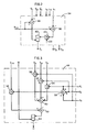
- the function blocks comprising the stage efficiency model 34 are illustrated in Fig. 2. In this Fig., the input enthalpy hi n is used as an input to both subtraction function blocks 36 and 38.
- the second input to the subtraction function block 36 is the first stage actual enthalpy h 1
- the second input to the subtraction function block 38 is the first stage enthalpy of ideal (isentropic) expansion 1 .
- subtraction function block 36 produces a signal representative of hi n - h l at its output
- subtraction function block 38 produces a signal representative of h in - 1 at its output.
- the output signal from the function block 36 is then used as an input to a multiplication function block 40 wherein it is multiplied by the factor 100.
- the output of the multiplication function block 40, along with the output of the subtraction function block 38, are then used as inputs to a division function block 42 which produces an output signal n 1 representative of stage efficiency according to the following equation: It should be noted that the efficiency of any stage of the energy converter can be determined in a similar manner.
- the power output (w) of the energy converter 12 is measured by a power transmitter 44 whose output is used as an input to a heat rate module 46 for actual conditions.
- Another input to this module 46 is the flow F 1 of the fluid extracted from the first stage of the energy converter 12.
- This fluid flow F 1 is measured by a flow transmitter 48.
- the flows F 2 , F 3 from the other stages are also measured by similar transmitters (not shown) and are used as inputs to this module 46.
- Other inputs to this module 46 include the input en- t hal py hin , and the enthalpies h 1 , h 2 , and h 3 of the fluid extracted from each stage of the energy converter under actual conditions.
- the function blocks comprising the actual heat rate module 46 and the foregoing inputs are illustrated in Fig. 3.
- the fluid flows F 1 , F 2 , and F 3 are used as inputs to a summation function block 50 which produces an output signal representative of the total fluid flow extracted from the stages of the energy converter.
- the fluid flow into the energy converter 12 is also equal to the sum of the flows F 1 , F 2 and F 3 .
- the output signal from the summation function block 50 is used as an input to a multiplication function block 52 along with the input enthalpy hi n .
- the multiplication function block 52 produces an output signal representative of the flow rate of energy into the energy converter.
- multiplication function blocks 54, 56, and 58 are provided wherein the fluid flows F 1 , F 2 , and F 3 from each stage of the converter are multiplied by their respective enthalpy contents, i.e., fluid flow F l is multiplied by its enthalpy content h 1 in multiplication function block 54; fluid flow F 2 is multiplied by its enthalpy content h 2 in multiplication function block 56; and fluid flow F 3 is multiplied by its enthalpy content h 3 in multiplication function block 58.
- the output of the function blocks 54, 56, and 58 are used as inputs to a summation function block 60 which produces an output signal representative of the rate of flow of energy leaving the energy converter 12.
- This signal, along with the output of the multiplication function block 52, are used as inputs to a subtraction function block 62 wherein the output of the summation function block 60 is subtracted from the output of the multiplication function block 52 to produce an output signal representative of the rate of energy used by the energy converter.
- This output signal and the power output (w) are used as inputs to a division function block 64 wherein the output of the subtraction function block 62 is divided by the power output (w) to produce an output signal H representative of the energy inputted to the converter to generate a unit of energy output.
- the power output (w) of the energy converter 12 the flows F l , F 2 , and F 3 of the fluids being extracted from the stages of the energy converter, the input enthalpy hi n , and the enthalpies 1 , 2 , and 3 of the fluids extracted from each stage of the converter under ideal (isentropic) conditions are inputs to a heat rate module 66 for ideal conditions.
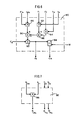
- the foregoing input signals are applied to the function blocks shown in Fig. 4 which illustrates the blocks which comprise the heat rate module 66 for ideal conditions.
- the functional logic utilized in Fig. 4 is identical to that utilized in. Fig.
- the output signal H.produced by the module 66 is representative of the energy inputted to the converter to generate a unit of energy output under ideal (isentropic) conditions.
- the efficiency of the energy converter 12 is determined by the overall efficiency module 68 illustrated in Fig..l.
- the heat rates H and H corresponding to the actual and the ideal (isentropic) conditions, respectively are inputs to this module 68 and are applied to the function blocks, shown in Fig. 5, which comprise this module 68.
- the other input to this module 68 is a constant equal to 3412.7 (100).
- the actual heat rate H and the constant 3412.7 (100) are used as inputs to a division function block 70 wherein the constant 3412.7 (100) is divided by the heat rate H to produce an output signal representative of the mechanical efficiency n m of the energy converter.
- the actual heat rate H and the ideal heat rate H are used as inputs to a division function block 72 wherein the actual heat rate H is divided by the ideal heat rate H to produce an output signal which is used as an input to a multiplication function block 74 wherein this signal is multiplied by the factor 100 to produce an output signal which is representative of the combined stage efficiency n c of the energy converter.
- This output signal n c along with the output signal n m are used as inputs to a multiplication function block 76 to produce an output signal which is subsequently divided by the factor 100 in a division function block 78.
- the function block 78 produces an output signal which is representative of the overall efficiency n t of the energy converter.
- Steam cost can also be determined by the logic illustrated in Fig. 1, and such a determination is accomplished by the cost of generation module 80.
- This module 80 uses the enthalpies h I and h 2 and the respective fluid flows F 1 and F 2 corresponding to the first and second extraction stages (the third extraction stage is excluded because the energy extracted from this stage has no utility value), the input flow Fi n and the input enthalpy hi n to the energy converter, the power output (w) of the energy converter, and the cost C s of the fluid entering the energy converter as inputs thereto.
- the foregoing inputs are applied to the function blocks, shown in Fig. 6, which comprise this module 80.
- Fig. 6 which comprise this module 80.
- the enthalpies h l and h 2 and the fluid flow F 1 and F 2 are inputs to the multiplication function blocks 82 and 84, respectively.
- Each of these function blocks 82 and 84 produces an output signal which is an input to a summation function block 86 which produces an output signal that is representative of the rate of energy flow leaving the energy converter through the first and second stages thereof.
- the input enthalpy hi n is multiplied by the input flow Fi n in multiplication function block 88 to produce an output signal which is representative of such energy flow rate.
- This output signal along with the output signal from the summation function block 86, are used as inputs to a subtraction function block 90 wherein the output signal from the summation function block 86 is subtracted from the output signal from the multiplication function block 88 to produce an output signal which is subsequently multiplied by the fluid cost C s in a multiplication function block 92 to produce an output signal representative of the cost flow F e into the energy converter.
- This output signal representative of cost flow F e along with the power output (w), are then used as inputs to a division function block 94 wherein the cost flow F e is divided by the power output (w) to produce an output signal representative of the cost C e of the energy output.
- the extraction efficiency of each stage of the energy converter is determined by the extraction efficiency module 96.
- the inputs to this module 96 include the mechanical efficiency n m of the energy converter and the stage efficiencies n l , n 2 , and n 3 .
- the foregoing inputs are shown in Fig. 7 which illustrates the function block which comprises this module 96.
- the mechanical efficiency n m and the first stage efficiency n 1 are used as inputs to a multiplication function block 98 which produces an output signal which is representative of the extraction efficiency n t1 of the first stage of the energy converter.
- the extraction efficiencies n t2 and n t3 for the second and third stages, respectively can be obtained in a similar manner.
Landscapes
- Chemical & Material Sciences (AREA)
- Engineering & Computer Science (AREA)
- Combustion & Propulsion (AREA)
- Physics & Mathematics (AREA)
- General Physics & Mathematics (AREA)
- Measuring Fluid Pressure (AREA)
- Testing Of Devices, Machine Parts, Or Other Structures Thereof (AREA)
- Investigating Or Analyzing Materials Using Thermal Means (AREA)
- Testing Or Calibration Of Command Recording Devices (AREA)
- Management, Administration, Business Operations System, And Electronic Commerce (AREA)
- Measuring Temperature Or Quantity Of Heat (AREA)
- Testing And Monitoring For Control Systems (AREA)
- Feedback Control In General (AREA)
Applications Claiming Priority (2)
| Application Number | Priority Date | Filing Date | Title |
|---|---|---|---|
| US43995382A | 1982-11-08 | 1982-11-08 | |
| US439953 | 1995-05-12 |
Publications (2)
| Publication Number | Publication Date |
|---|---|
| EP0113170A2 true EP0113170A2 (de) | 1984-07-11 |
| EP0113170A3 EP0113170A3 (de) | 1984-09-26 |
Family
ID=23746799
Family Applications (1)
| Application Number | Title | Priority Date | Filing Date |
|---|---|---|---|
| EP83306626A Ceased EP0113170A3 (de) | 1982-11-08 | 1983-10-31 | Bestimmung des Verbrauchs eines Energiespeichervektors |
Country Status (9)
| Country | Link |
|---|---|
| EP (1) | EP0113170A3 (de) |
| JP (1) | JPS59132347A (de) |
| KR (1) | KR890001935B1 (de) |
| AU (1) | AU563547B2 (de) |
| BR (1) | BR8306281A (de) |
| CA (1) | CA1214554A (de) |
| ES (1) | ES8504386A1 (de) |
| IN (1) | IN162845B (de) |
| MX (1) | MX159239A (de) |
Cited By (1)
| Publication number | Priority date | Publication date | Assignee | Title |
|---|---|---|---|---|
| EP0156583A3 (de) * | 1984-03-23 | 1989-03-01 | International Control Automation Finance S.A. | Enthalpiemessung für eine zweiphasige Substanz |
Family Cites Families (3)
| Publication number | Priority date | Publication date | Assignee | Title |
|---|---|---|---|---|
| JPS5392540A (en) * | 1977-01-24 | 1978-08-14 | Toshiba Corp | Control device for cooling using outdoor air |
| US4244216A (en) * | 1979-01-08 | 1981-01-13 | The Babcock & Wilcox Company | Heat flow meter |
| JPS55142241A (en) * | 1979-04-24 | 1980-11-06 | Daikin Ind Ltd | Device for measuring degree of dryness of liquid-gas mixed coolant in refrigerator |
-
1983
- 1983-10-29 IN IN1331/CAL/83A patent/IN162845B/en unknown
- 1983-10-31 EP EP83306626A patent/EP0113170A3/de not_active Ceased
- 1983-11-04 AU AU20993/83A patent/AU563547B2/en not_active Ceased
- 1983-11-04 KR KR1019830005243A patent/KR890001935B1/ko not_active Expired
- 1983-11-07 ES ES527073A patent/ES8504386A1/es not_active Expired
- 1983-11-07 CA CA000440578A patent/CA1214554A/en not_active Expired
- 1983-11-07 JP JP58207652A patent/JPS59132347A/ja active Granted
- 1983-11-08 MX MX199335A patent/MX159239A/es unknown
- 1983-11-08 BR BR8306281A patent/BR8306281A/pt not_active IP Right Cessation
Cited By (1)
| Publication number | Priority date | Publication date | Assignee | Title |
|---|---|---|---|---|
| EP0156583A3 (de) * | 1984-03-23 | 1989-03-01 | International Control Automation Finance S.A. | Enthalpiemessung für eine zweiphasige Substanz |
Also Published As
| Publication number | Publication date |
|---|---|
| KR890001935B1 (ko) | 1989-05-31 |
| AU2099383A (en) | 1984-05-17 |
| JPH0345788B2 (de) | 1991-07-12 |
| CA1214554A (en) | 1986-11-25 |
| JPS59132347A (ja) | 1984-07-30 |
| KR840006697A (ko) | 1984-12-01 |
| EP0113170A3 (de) | 1984-09-26 |
| ES527073A0 (es) | 1985-04-01 |
| BR8306281A (pt) | 1984-06-19 |
| AU563547B2 (en) | 1987-07-16 |
| MX159239A (es) | 1989-05-08 |
| IN162845B (de) | 1988-07-16 |
| ES8504386A1 (es) | 1985-04-01 |
Similar Documents
| Publication | Publication Date | Title |
|---|---|---|
| US4814996A (en) | Portable energy cost calculation | |
| US4145922A (en) | Thermal power measurement apparatus | |
| KR890000888A (ko) | 터어빈 임펄스 실온 측정방법 및 장치 | |
| CN101737311B (zh) | 基于能量平衡的火电机组低加系统疏水泵流量测算方法 | |
| CN101737310B (zh) | 基于疏水泵流量软测量的泵效率测算方法 | |
| EP0113170A2 (de) | Bestimmung des Verbrauchs eines Energiespeichervektors | |
| US4612621A (en) | Distributed system for optimizing the performance of a plurality of multi-stage steam turbines using function blocks | |
| RU2103503C1 (ru) | Устройство для контроля дебитов компонентов продукции скважин | |
| RU2041450C1 (ru) | Теплосчетчик | |
| KR101334885B1 (ko) | 적분 평균 온도를 결정하기 위한 방법 | |
| SU1481604A1 (ru) | Устройство дл определени удельного расхода топлива в теплоэнергетических установках | |
| Sunde et al. | Data reconciliation in the steam-turbine cycle of a boiling water reactor | |
| RU2187886C1 (ru) | Устройство для преобразования чисел из кода системы остаточных классов в полиадический код | |
| SU1581965A1 (ru) | Способ определени запаса теплогидравлической устойчивости в парогенерирующем контуре | |
| GB2073411A (en) | Determining coolant flow rate of fuel elements | |
| SU1511522A2 (ru) | Способ определени запаса теплогидравлической устойчивости парогенерирующего канала | |
| RU2085875C1 (ru) | Устройство для учета тепловой энергии | |
| SU744565A1 (ru) | Множительное устройство | |
| Leung et al. | Closure to “Discussion of ‘Cycles for Supplying Steam to Desalting Evaporators of Dual-Purpose Power-Generation Plants’”(1966, ASME J. Eng. Power, 88, p. 283) | |
| SU1638559A1 (ru) | Устройство диагностики расходомеров | |
| SU1513305A1 (ru) | Диагностическа система Герлиги-Погосова-Хабенского дл контрол запаса теплогидравлической устойчивости парогенерирующего канала | |
| Hedley | Discussion:“Formation of SO3 in a Noncatalytic Combustor”(Barrett, Richard E., Hummell, John D., and Reid, William T., 1966, ASME J. Eng. Power, 88, pp. 165–172) | |
| SU1590832A1 (ru) | Система для контроля запаса теплогидравлической устойчивости парогенерирующего канала | |
| SU1476436A1 (ru) | Способ определени расхода газа и устройство дл его осуществлени | |
| SU756049A1 (ru) | Устройство для контроля прогрева ротора турбины 1 |
Legal Events
| Date | Code | Title | Description |
|---|---|---|---|
| PUAI | Public reference made under article 153(3) epc to a published international application that has entered the european phase |
Free format text: ORIGINAL CODE: 0009012 |
|
| AK | Designated contracting states |
Designated state(s): DE FR GB IT |
|
| PUAL | Search report despatched |
Free format text: ORIGINAL CODE: 0009013 |
|
| AK | Designated contracting states |
Designated state(s): DE FR GB IT |
|
| 17P | Request for examination filed |
Effective date: 19841208 |
|
| 17Q | First examination report despatched |
Effective date: 19860122 |
|
| R17C | First examination report despatched (corrected) |
Effective date: 19860820 |
|
| STAA | Information on the status of an ep patent application or granted ep patent |
Free format text: STATUS: THE APPLICATION HAS BEEN REFUSED |
|
| 18R | Application refused |
Effective date: 19890630 |
|
| APAF | Appeal reference modified |
Free format text: ORIGINAL CODE: EPIDOSCREFNE |
|
| RIN1 | Information on inventor provided before grant (corrected) |
Inventor name: DZIUBAKOWSKI, DONALD J. Inventor name: KAYA, AZMI Inventor name: KEYES, MARION A. IV |