EP0113440A1 - Relais électromagnétique - Google Patents
Relais électromagnétique Download PDFInfo
- Publication number
- EP0113440A1 EP0113440A1 EP83112209A EP83112209A EP0113440A1 EP 0113440 A1 EP0113440 A1 EP 0113440A1 EP 83112209 A EP83112209 A EP 83112209A EP 83112209 A EP83112209 A EP 83112209A EP 0113440 A1 EP0113440 A1 EP 0113440A1
- Authority
- EP
- European Patent Office
- Prior art keywords
- contact
- counter
- free end
- relay
- bridge
- Prior art date
- Legal status (The legal status is an assumption and is not a legal conclusion. Google has not performed a legal analysis and makes no representation as to the accuracy of the status listed.)
- Granted
Links
- 230000013011 mating Effects 0.000 claims description 10
- 238000005192 partition Methods 0.000 claims description 3
- 238000004519 manufacturing process Methods 0.000 abstract 1
- XEEYBQQBJWHFJM-UHFFFAOYSA-N Iron Chemical group [Fe] XEEYBQQBJWHFJM-UHFFFAOYSA-N 0.000 description 1
- 238000005452 bending Methods 0.000 description 1
- 238000011161 development Methods 0.000 description 1
- 230000018109 developmental process Effects 0.000 description 1
- 238000009413 insulation Methods 0.000 description 1
- 238000000034 method Methods 0.000 description 1
- 230000000284 resting effect Effects 0.000 description 1
- 238000004804 winding Methods 0.000 description 1
Images

Classifications
-
- H—ELECTRICITY
- H01—ELECTRIC ELEMENTS
- H01H—ELECTRIC SWITCHES; RELAYS; SELECTORS; EMERGENCY PROTECTIVE DEVICES
- H01H50/00—Details of electromagnetic relays
- H01H50/54—Contact arrangements
- H01H50/60—Contact arrangements moving contact being rigidly combined with movable part of magnetic circuit
-
- H—ELECTRICITY
- H01—ELECTRIC ELEMENTS
- H01H—ELECTRIC SWITCHES; RELAYS; SELECTORS; EMERGENCY PROTECTIVE DEVICES
- H01H50/00—Details of electromagnetic relays
- H01H50/54—Contact arrangements
- H01H50/546—Contact arrangements for contactors having bridging contacts
-
- H—ELECTRICITY
- H01—ELECTRIC ELEMENTS
- H01H—ELECTRIC SWITCHES; RELAYS; SELECTORS; EMERGENCY PROTECTIVE DEVICES
- H01H1/00—Contacts
- H01H1/12—Contacts characterised by the manner in which co-operating contacts engage
- H01H1/14—Contacts characterised by the manner in which co-operating contacts engage by abutting
- H01H1/20—Bridging contacts
- H01H1/2075—T-shaped bridge; bridging contact has lateral arm for mounting resiliently or on a pivot
-
- H—ELECTRICITY
- H01—ELECTRIC ELEMENTS
- H01H—ELECTRIC SWITCHES; RELAYS; SELECTORS; EMERGENCY PROTECTIVE DEVICES
- H01H1/00—Contacts
- H01H1/12—Contacts characterised by the manner in which co-operating contacts engage
- H01H1/14—Contacts characterised by the manner in which co-operating contacts engage by abutting
- H01H1/24—Contacts characterised by the manner in which co-operating contacts engage by abutting with resilient mounting
- H01H2001/247—Contacts characterised by the manner in which co-operating contacts engage by abutting with resilient mounting using an elastic hinge, the contact being composed of rigid parts connected by thinned flexible hinge parts
Definitions
- the invention relates to an electromagnetic relay with a coil former serving as a support, an angular yoke, the first leg of which is coupled to a first pole end of a coil core and the second leg forms a bearing edge for a flat armature, which forms a working air gap with the second pole end of the coil core , wherein a contact spring connected to the armature extends beyond its free end into a contact pocket formed on the coil body and connects there counter contact pieces that are aligned with one another at least in a switching position, the bearing axis of the armature or the contact spring being perpendicular to the base plane of the relay.
- the object of the invention is therefore to create a relay of the type mentioned at the outset, in which a bridge contact arrangement is formed with as few and simple parts as possible, in which the contact pressure is the same at all contact points and which is used as a bridge closer without constructive change by appropriately inserting contact elements, can be configured as a bridge opener and as a bridge switch.
- both the mating contact pieces carrying mating contact elements are designed as flat, anchored in a common plane in the carrier plates, wherein the first overall - gen giftedelement at its free end a lying in the common plane, the free end of second cross-contact element projecting cross leg.
- the two mating contact elements Due to the angular or hook-shaped shape of the first mating contact element, which is otherwise designed as a flat cut part, it is possible to arrange the two mating contact elements to be contacted jointly by the bridge contact spring in the longitudinal direction of the bridge contact spring with the necessary large spacing and nevertheless to provide the contact points of the two mating contact elements one above the other, so that both have the same distance from the pivot axis of the bridge contact spring and thus receive the same contact pressure.
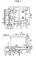
- the relay shown in FIGS. 1 to 3 has a coil body 1 with a winding 2, which is applied between the flanges 3 and 4.
- An iron core 3 is arranged in the coil body 1 along the coil axis and is connected at one end 5a to the first leg 6a of an angular yoke 6.
- the other end 5b of the core serves as a pole face and forms a working air gap with an armature 7, which lies with an extension 7a in a recess 6c of the second yoke leg 6b and is mounted on a bearing cutting edge 6d.
- the armature By means of a return spring in the form of a coil spring 8, the armature is pulled into its resting position, while it is attracted in the response of the relay against the force of the spring 8 to the end of the core 5b and thereby switches the befe- sti g te thereon bridge contact spring. 9
- the relay corresponds to a known structure.
- the contact arrangement is arranged in a contact pocket 10, this contact pocket being formed in one piece with the coil former by an extension 11 on the coil former flange 4.
- Four receiving slots 12, 13, 14 and 15 are provided in the contact pocket for receiving counter-contact elements. in the illustrated embodiment, only the receiving slots 12 and 13 are equipped with counter-contact elements 16 and 17, while the opposite receiving slots 14 and 15 remain free. So that the relay shown is a bridge closer formed, since the rest side of the bridge contact spring 9 is not equipped.
- the receiving slots 14 and 15 not used in all of the embodiments are expediently closed by thin mold partitions, which are only pierced through the inserted connecting pin of the mating contact elements when these receiving slots are fitted.
- the short counter-contact element 17 carries a contact rivet 17b at its free end 17a, while the longer counter-contact element 16 has a cross leg 16a at its free end, which projects beyond the free end 17a of the other contact element and carries a contact rivet 16b in the region above the second counter-contact element 17 .
- the two mating contact elements 16 and 17 thus lie entirely in one plane, their two contact rivets 16b and 17b being at the same distance from the pivot axis of the bridge contact spring 9, so that when the armature 7 is tightened, both contact rivets 16b and 17b simultaneously with the contact rivets 9a and 9b of the Bridge contact piece 9c come into contact and the torsional contact spring 9 applies the same contact pressure.
- the connecting pins 16c and 17c of the mating contact elements 16 and 17 are designed such that they are as far apart as possible.
- a partition 18 is provided in the contact pocket to increase the insulation strength between the mating contact elements and to improve the rigidity of the carrier.
- the receiving slots 14 and 15 could also be provided with counter-contact elements 16 and 17, which would form a normally closed contact with the contact spring 9, so that the relay as a whole would be designed as a bridge switch.
- the bridge contact spring 9 only needs to conduct the switching current with its bridge contact piece 9c at the free end, so that it can also be attached to the armature 7 in an insulated manner if necessary.
- the bridge contact piece 9c and its fastening end 9d In the area between the bridge contact piece 9c and its fastening end 9d, it has a web 9e reduced by incisions in cross section, the width of which is smaller than the distance between the contact rivets 9a and 9b.
- This narrow bridge thus acts as a torsion bridge, through which different contact openings of the upper and lower contacts can be compensated in order to obtain the same contact forces.
- the contact spring In the region between the fastening end 9d and the web 9e, the contact spring has a trapezoidal section, as a result of which the elastic deflection is improved. In this trapezoidal section, a pretensioning bend 9f is also provided, which increases the contact forces and improves the burn-off safety.
- the contact spring 9 is rounded on its outer edges in the region of its bridge contact piece 9c.
- it has a projecting tab 9g at its free end, which in the embodiment shown strikes a stop lug 19 and thereby the rest position of the anchor.
Landscapes
- Physics & Mathematics (AREA)
- Electromagnetism (AREA)
- Electromagnets (AREA)
- Breakers (AREA)
Applications Claiming Priority (2)
| Application Number | Priority Date | Filing Date | Title |
|---|---|---|---|
| DE8234360U DE8234360U1 (de) | 1982-12-07 | 1982-12-07 | Elektromagnetisches Relais |
| DE8234360U | 1982-12-07 |
Publications (2)
| Publication Number | Publication Date |
|---|---|
| EP0113440A1 true EP0113440A1 (fr) | 1984-07-18 |
| EP0113440B1 EP0113440B1 (fr) | 1986-06-04 |
Family
ID=6746280
Family Applications (1)
| Application Number | Title | Priority Date | Filing Date |
|---|---|---|---|
| EP83112209A Expired EP0113440B1 (fr) | 1982-12-07 | 1983-12-05 | Relais électromagnétique |
Country Status (4)
| Country | Link |
|---|---|
| US (1) | US4509028A (fr) |
| EP (1) | EP0113440B1 (fr) |
| JP (1) | JPS59111221A (fr) |
| DE (2) | DE8234360U1 (fr) |
Cited By (1)
| Publication number | Priority date | Publication date | Assignee | Title |
|---|---|---|---|---|
| EP1280175A3 (fr) * | 2001-07-27 | 2004-10-13 | Tyco Electronics AMP GmbH | Relais |
Families Citing this family (5)
| Publication number | Priority date | Publication date | Assignee | Title |
|---|---|---|---|---|
| US4937544A (en) * | 1988-01-29 | 1990-06-26 | Siemens Aktiengesellschaft | "Contact arrangement for a relay" |
| DE9015406U1 (de) * | 1990-11-09 | 1992-03-05 | Siemens AG, 8000 München | Elektromagnetisches Relais mit auf dem Anker befestigter Kontaktfeder |
| DE19933797A1 (de) * | 1999-07-19 | 2001-03-08 | Tyco Electronics Logistics Ag | Relais mit Wippanker |
| JP5222669B2 (ja) * | 2008-09-16 | 2013-06-26 | 富士通コンポーネント株式会社 | 電磁継電器 |
| CN103337415A (zh) * | 2013-06-14 | 2013-10-02 | 东莞市三友联众电器有限公司 | 一种继电器接触系统 |
Citations (8)
| Publication number | Priority date | Publication date | Assignee | Title |
|---|---|---|---|---|
| US3555230A (en) * | 1968-11-12 | 1971-01-12 | American Mach & Foundry | Contact isolating means for multipoled switch devices |
| US4034323A (en) * | 1975-03-24 | 1977-07-05 | Oki Electric Industry Company, Ltd. | Magnetic relay |
| DE2638941B1 (de) * | 1976-08-28 | 1977-12-29 | Schadow Rudolf Gmbh | Tastenaggregat mit nebeneinander angeordneten schiebetastenschaltern |
| US4254391A (en) * | 1979-09-17 | 1981-03-03 | Fasco Industries, Inc. | Split armature relay |
| EP0038727A1 (fr) * | 1980-03-21 | 1981-10-28 | ETS BERNIER & CIE Société Anonyme | Relais électromagnétique à armature pivotante à aimant permanent |
| DE3043447A1 (de) * | 1980-11-18 | 1982-07-01 | Rausch & Pausch, 8672 Selb | Relais mit einem gehaeuse oder einer abdeckkappe |
| DE8125818U1 (de) * | 1981-09-04 | 1982-10-14 | Siemens AG, 1000 Berlin und 8000 München | Elektromagnetisches Schaltrelais für hohe Strombelastung |
| EP0099019A1 (fr) * | 1982-06-30 | 1984-01-25 | Siemens Aktiengesellschaft | Relais avec ressort de contact de pontage |
Family Cites Families (2)
| Publication number | Priority date | Publication date | Assignee | Title |
|---|---|---|---|---|
| GB1200321A (en) * | 1967-01-16 | 1970-07-29 | Lucas Industries Ltd | Electromagnetic relays |
| JPS5322734U (fr) * | 1976-07-31 | 1978-02-25 |
-
1982
- 1982-12-07 DE DE8234360U patent/DE8234360U1/de not_active Expired
-
1983
- 1983-10-28 US US06/546,450 patent/US4509028A/en not_active Expired - Fee Related
- 1983-11-28 JP JP58222275A patent/JPS59111221A/ja active Granted
- 1983-12-05 EP EP83112209A patent/EP0113440B1/fr not_active Expired
- 1983-12-05 DE DE8383112209T patent/DE3363967D1/de not_active Expired
Patent Citations (8)
| Publication number | Priority date | Publication date | Assignee | Title |
|---|---|---|---|---|
| US3555230A (en) * | 1968-11-12 | 1971-01-12 | American Mach & Foundry | Contact isolating means for multipoled switch devices |
| US4034323A (en) * | 1975-03-24 | 1977-07-05 | Oki Electric Industry Company, Ltd. | Magnetic relay |
| DE2638941B1 (de) * | 1976-08-28 | 1977-12-29 | Schadow Rudolf Gmbh | Tastenaggregat mit nebeneinander angeordneten schiebetastenschaltern |
| US4254391A (en) * | 1979-09-17 | 1981-03-03 | Fasco Industries, Inc. | Split armature relay |
| EP0038727A1 (fr) * | 1980-03-21 | 1981-10-28 | ETS BERNIER & CIE Société Anonyme | Relais électromagnétique à armature pivotante à aimant permanent |
| DE3043447A1 (de) * | 1980-11-18 | 1982-07-01 | Rausch & Pausch, 8672 Selb | Relais mit einem gehaeuse oder einer abdeckkappe |
| DE8125818U1 (de) * | 1981-09-04 | 1982-10-14 | Siemens AG, 1000 Berlin und 8000 München | Elektromagnetisches Schaltrelais für hohe Strombelastung |
| EP0099019A1 (fr) * | 1982-06-30 | 1984-01-25 | Siemens Aktiengesellschaft | Relais avec ressort de contact de pontage |
Cited By (1)
| Publication number | Priority date | Publication date | Assignee | Title |
|---|---|---|---|---|
| EP1280175A3 (fr) * | 2001-07-27 | 2004-10-13 | Tyco Electronics AMP GmbH | Relais |
Also Published As
| Publication number | Publication date |
|---|---|
| DE3363967D1 (en) | 1986-07-10 |
| DE8234360U1 (de) | 1983-06-09 |
| JPS59111221A (ja) | 1984-06-27 |
| EP0113440B1 (fr) | 1986-06-04 |
| US4509028A (en) | 1985-04-02 |
| JPS6410899B2 (fr) | 1989-02-22 |
Similar Documents
| Publication | Publication Date | Title |
|---|---|---|
| EP0107611B1 (fr) | Dispositif de sectionnement avec lamelles de contact pontant pour appareil interrupteur débrochable | |
| EP0281950B1 (fr) | Relais électromagnétique | |
| EP0735628A2 (fr) | Barre omnibus avec borne | |
| EP0363976B1 (fr) | Relais électromagnétique | |
| EP0033841B1 (fr) | Relais | |
| EP0129068B1 (fr) | Relais électromagnétique miniaturisé et méthode de fabrication | |
| EP0640242B1 (fr) | Agencement de lames de contact de relais de transmission et de commutation de courants eleves | |
| DE4035586C2 (de) | Elektromagnetisches Relais | |
| DE3217528C2 (de) | Kontaktanordnung für Relais | |
| EP0086316B1 (fr) | Dispositif à contact enfichable pour la réalisation d'une connexion électrique entre deux barres omnibus | |
| DE3443094C2 (de) | Elektromagnetisches Relais | |
| DE3232679C2 (de) | Elektromagnetisches Schaltrelais für hohe Strombelastung | |
| EP0113440A1 (fr) | Relais électromagnétique | |
| EP0099019A1 (fr) | Relais avec ressort de contact de pontage | |
| DE60203765T2 (de) | Schaltrelais mit verbesserter Ankerfeder | |
| EP1018129A1 (fr) | Relais electromagnetique | |
| EP0081164A1 (fr) | Relais électromagnétique | |
| DE2545180C3 (de) | Miniaturrelais | |
| EP0252344A1 (fr) | Relais électromagnétique | |
| EP0267145A2 (fr) | Borne à découpage et serrage pour conducteur électrique | |
| DE2345638C2 (fr) | ||
| EP3561830B1 (fr) | Dispositif de contact de commutation | |
| DE19540739A1 (de) | Relais mit zwangsgeführten Kontakten | |
| DE3508795C2 (fr) | ||
| EP0192928A1 (fr) | Relais électromagnétique |
Legal Events
| Date | Code | Title | Description |
|---|---|---|---|
| PUAI | Public reference made under article 153(3) epc to a published international application that has entered the european phase |
Free format text: ORIGINAL CODE: 0009012 |
|
| AK | Designated contracting states |
Designated state(s): CH DE FR GB LI |
|
| 17P | Request for examination filed |
Effective date: 19841128 |
|
| GRAA | (expected) grant |
Free format text: ORIGINAL CODE: 0009210 |
|
| AK | Designated contracting states |
Kind code of ref document: B1 Designated state(s): CH DE FR GB LI |
|
| REF | Corresponds to: |
Ref document number: 3363967 Country of ref document: DE Date of ref document: 19860710 |
|
| ET | Fr: translation filed | ||
| PLBE | No opposition filed within time limit |
Free format text: ORIGINAL CODE: 0009261 |
|
| STAA | Information on the status of an ep patent application or granted ep patent |
Free format text: STATUS: NO OPPOSITION FILED WITHIN TIME LIMIT |
|
| 26N | No opposition filed | ||
| PGFP | Annual fee paid to national office [announced via postgrant information from national office to epo] |
Ref country code: CH Payment date: 19960320 Year of fee payment: 13 |
|
| PGFP | Annual fee paid to national office [announced via postgrant information from national office to epo] |
Ref country code: GB Payment date: 19961118 Year of fee payment: 14 |
|
| PG25 | Lapsed in a contracting state [announced via postgrant information from national office to epo] |
Ref country code: LI Effective date: 19961231 Ref country code: CH Effective date: 19961231 |
|
| REG | Reference to a national code |
Ref country code: CH Ref legal event code: PL |
|
| PG25 | Lapsed in a contracting state [announced via postgrant information from national office to epo] |
Ref country code: GB Free format text: LAPSE BECAUSE OF NON-PAYMENT OF DUE FEES Effective date: 19971205 |
|
| GBPC | Gb: european patent ceased through non-payment of renewal fee |
Effective date: 19971205 |
|
| PGFP | Annual fee paid to national office [announced via postgrant information from national office to epo] |
Ref country code: FR Payment date: 20011203 Year of fee payment: 19 |
|
| PGFP | Annual fee paid to national office [announced via postgrant information from national office to epo] |
Ref country code: DE Payment date: 20021230 Year of fee payment: 20 |
|
| PG25 | Lapsed in a contracting state [announced via postgrant information from national office to epo] |
Ref country code: FR Free format text: LAPSE BECAUSE OF NON-PAYMENT OF DUE FEES Effective date: 20030901 |
|
| REG | Reference to a national code |
Ref country code: FR Ref legal event code: ST |