EP0113491A1 - Elektrischer Hochspannungsverbinder - Google Patents
Elektrischer Hochspannungsverbinder Download PDFInfo
- Publication number
- EP0113491A1 EP0113491A1 EP83300060A EP83300060A EP0113491A1 EP 0113491 A1 EP0113491 A1 EP 0113491A1 EP 83300060 A EP83300060 A EP 83300060A EP 83300060 A EP83300060 A EP 83300060A EP 0113491 A1 EP0113491 A1 EP 0113491A1
- Authority
- EP
- European Patent Office
- Prior art keywords
- axially
- shearable
- stop
- piston
- kinetic energy
- Prior art date
- Legal status (The legal status is an assumption and is not a legal conclusion. Google has not performed a legal analysis and makes no representation as to the accuracy of the status listed.)
- Granted
Links
- 238000010521 absorption reaction Methods 0.000 claims abstract description 28
- 230000004044 response Effects 0.000 claims abstract description 23
- 238000010791 quenching Methods 0.000 claims abstract description 16
- 230000001133 acceleration Effects 0.000 claims abstract description 5
- 239000000463 material Substances 0.000 claims description 23
- 230000008878 coupling Effects 0.000 claims description 19
- 238000010168 coupling process Methods 0.000 claims description 19
- 238000005859 coupling reaction Methods 0.000 claims description 19
- 238000010008 shearing Methods 0.000 claims description 17
- 230000004323 axial length Effects 0.000 claims description 11
- 230000000295 complement effect Effects 0.000 claims description 5
- 230000006872 improvement Effects 0.000 claims description 4
- 230000003292 diminished effect Effects 0.000 claims 2
- VRDIULHPQTYCLN-UHFFFAOYSA-N Prothionamide Chemical compound CCCC1=CC(C(N)=S)=CC=N1 VRDIULHPQTYCLN-UHFFFAOYSA-N 0.000 claims 1
- 238000013459 approach Methods 0.000 claims 1
- 239000004020 conductor Substances 0.000 claims 1
- 239000007789 gas Substances 0.000 abstract description 17
- 230000008901 benefit Effects 0.000 description 3
- 238000010276 construction Methods 0.000 description 3
- 230000000694 effects Effects 0.000 description 3
- 239000013536 elastomeric material Substances 0.000 description 2
- 238000013022 venting Methods 0.000 description 2
- 230000000712 assembly Effects 0.000 description 1
- 238000000429 assembly Methods 0.000 description 1
- 230000018109 developmental process Effects 0.000 description 1
- 238000003780 insertion Methods 0.000 description 1
- 230000037431 insertion Effects 0.000 description 1
- 239000002184 metal Substances 0.000 description 1
- 230000009467 reduction Effects 0.000 description 1
- 238000007789 sealing Methods 0.000 description 1
- 239000013589 supplement Substances 0.000 description 1
Images


Classifications
-
- H—ELECTRICITY
- H01—ELECTRIC ELEMENTS
- H01R—ELECTRICALLY-CONDUCTIVE CONNECTIONS; STRUCTURAL ASSOCIATIONS OF A PLURALITY OF MUTUALLY-INSULATED ELECTRICAL CONNECTING ELEMENTS; COUPLING DEVICES; CURRENT COLLECTORS
- H01R13/00—Details of coupling devices of the kinds covered by groups H01R12/70 or H01R24/00 - H01R33/00
- H01R13/46—Bases; Cases
- H01R13/53—Bases or cases for heavy duty; Bases or cases for high voltage with means for preventing corona or arcing
-
- H—ELECTRICITY
- H01—ELECTRIC ELEMENTS
- H01H—ELECTRIC SWITCHES; RELAYS; SELECTORS; EMERGENCY PROTECTIVE DEVICES
- H01H33/00—High-tension or heavy-current switches with arc-extinguishing or arc-preventing means
- H01H33/02—Details
- H01H33/04—Means for extinguishing or preventing arc between current-carrying parts
- H01H33/045—Means for extinguishing or preventing arc between current-carrying parts for arcs formed during closing
Definitions
- the present invention relates generally to electrical connectors and pertains, more specifically, to electrical connectors of the type used in making a connection in an energized high voltage circuit of an electrical distribution system.
- Another object of the invention is to provide an electrical connector of the type described and in which the movable contact assembly may be accelerated to a greater speed and then stopped, subsequent to making contact, without a catastrophic failure within the connector.
- Still another object of the invention is to provide an electrical connector of the type described and in which the movable contact assembly is decelerated by kinetic energy absorption and dissigation means, thereby enabling the accomo- dation of higher arc-quenching gas pressures and concomitant higher speeds of movement of the movable contact assembly.
- Yet another object of the invention is to provide an electrical connector which employs the proved construction arrangement of previous movable contact assembly connectors together with improvements which render the electrical connector suitable for use in making fault closure connections at significantly higher voltages.
- a further object of the invention is to provide an electrical connector of the type described and which includes an external configuration that renders the connector compatible with existing high voltage electrical distribution systems.
- the present invention which may be described briefly as an improvement in an electrical connector of the type in which a contact element assembly is movable within the electrical connector from a first position to a second position to aceelerate a first contact element for rapid movement toward engagement with a complementary second contact element brought toward separable engagement with the first contact element within the electrical connector to complete an energized high voltage circuit, the improvement comprising kinetic energy absorption and dissipation means associated with the electrical connector for gradually absorbing and dissipating at least a portion of the kinetic energy imparted to the contact element assembly as a result of such acceleration as the contact element assembly moves from the first position toward the second position so as subsequently to decelerate the contact element assembly and thereby facilitate bringing the contact element assembly to a halt subsequent to the engagement of the first and second contact elements.
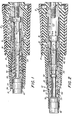
- Bushing insert 10 is for use in separable connection with a complementary male connector element, such as a connector elbow (not shown), in an energized high voltage circuit of an electrical distribution system (also not shown).
- Bushing insert 10 has a housing 12 which includes an outer housing casing 14 of elastomeric materials having an inner portion 16 of insulating elastomeric material and an outer portion 18 of conductive elastomeric material molded integral with inner portion 16.
- Housing 12 further includes a rigid, metallic, electrically conductive inner housing member 20 which extends longitudinally between a forward end 22 and a rearward end 24 within casing 14.
- a threaded aperture 26 at the rearward end 24 receives a threaded stud 28 which is unitary with one end of a metallic, electrically conductive extension 30 which itself is threaded at the other end thereof (not shown) for attachment to a high voltage circuit, such as at the terminal of a transformer (not shown).
- a tubular insulating noisepiece 32 is threaded into the inner housing member 20 at the forward end 22 thereof and projects axially therefrom, in a manner now well-knowm in bushing inserts, and carries an annular detent groove 34 adjacent the forward end 36 thereof for engaging a complementary detent in the male connector element which will be connected with the bushing insert 10.
- a carrier member 40 which is generally tubular and extends between forward end 42 and rearward end 44, corresponding to the forward and rearward ends 22 and 24 of the inner housing member 20.
- a piston 46 is unitary with the carrier member 40 adjacent rearward end 44 and is received within cylindrical inner surface 48 of inner housing member 20 for axial sliding movement.
- a female contact element 5Q is threaded into the carrier member 40 at the forward end 42 thereof so as to be integral with the carrier member 40 and movable axially with movement of he piston 46 and the carrier member 40.
- a tubular sleeve 52 of relatively soft insulating plastic material is secured to the female contact element 50 as by fasteners 54 and extends forward beyond the forward end of the female contact element 50 to provide a forward tubular portion 56 within which there is seated a first tubular guide 60, aligned axially with the female contact element 50, and a second tubular guide 62, also aligned axially with the female contact element, both guides 60 and 62 being affixed to the tubular portion 56.
- Guide 60 is constructed of a material from which arc-quenching gases will evolve in response to an arc being struck between an inserted male contact element (not shown) and the female contact element 50, and each guide 60 and 62 serves to receive and guide a follower (not shown) of arc-quenching gas-evolving material which projects from the male contact element and precedes the male contact element as contact is made with the female contact element 50.
- Guide 62 provides a sealing arrangement for confining the arc-quenching gase as the gases are evolved within bushing insert 10, in a manner already known in the art.
- female contact assembly 70 Forward axial movement of the female contact assembly 70 will be continued until piston 46 reaches the position illustrated in FIG. 3, at which position the male contact element and the female contact element 50 will be fully engaged and the female contact assembly 70 will be stopped.
- female contact assembly 70 will travel axially, in response to the generation of arc-quenching gases, from an initial retracted location, as seen in FIG. 1, to a final advanced location, as seen in FIG. 3, passing through an intermediate location, as depicted in FIG. 2.
- the arc struck between the male contact element and the female contact element very quickly will generate a relatively large volume of gases, especially in circuits where the voltages can be as high as about 35 kV.
- the higher voltages will produce an arc of greater axial length, requiring a greater length of travel between the retracted location and the advanced location of the female contact assembly.
- the piston 46, and indeed the entire female contact assenbly 70 will be accelerated to a relatively high speed and will possess a considerable amount of kinetic energy during travel from the retracted locations to the advanced location.
- bashing insert 10 includes kinetic energy absorption and dissipation means for absorbing and dissipating the kinetic energy of female contact assembly 70 as the assembly moves toward the advanced location.
- the kinetic energy absorption and dissipation means is constructed as follows.
- a stop member in the form of a ring 72 of relatively bard metal is affixed to the inner housing member 20 adjacent the forward end 22 by means of a threaded connection at 74.
- a stop shoulder 76 is located on the carrier member 40 at the forward end of piston 46.
- Carrier member 40 has an outer cylindrical surface 78 which is spaced radially inwardly from cylindrical inner surface 48 of inner housing member 20.
- Shearable members in the form of shearable rings 80, 82 and 84 are unitary with carrier member 40 and project radially outwardly toward inner housing member 20 to establish shearable means.
- Primary shearable ring 8Q is located adjacent the forward end 42 of carrier member 40 to provide a primary shearable structure while secondary shearable rings 82 and 84 are spaced axially from primary shearable ring 80 and from one another to provide a secondary shearable structure.
- Primary shearable ring 80 is spaced axially rearwardly from stop ring 72.
- the female contact assembly 70 Upon. the striking of an arc, and the consequent generation of arc-quenching gases, the female contact assembly 70 will be accelerated for rapid movement forward from the initial location, depicted in FIG. 1, and over the length of travel defined by the axial spacing between primary shearable ring 8Q and stop ring 72. Such unimpeded acceleration will result in high speed travel of the female contact assembly enabling rapid closing of the gap between the male contact element and the female contact element 50 and consequent reduction of arcing time. Initial contact will be made between the male contact element and female contact element 50, and the arc will be extinguished, when the female contact assembly 70 is in the vicinity of the intermediate location shown in FIG. 2.
- the gradual absorption and dissipation of kinetic energy brought about by the serial shearing of rings 80, 82 and 84 serves to decelerate and aid in bringing to a stop the female contact assembly 70 without a catastrophic failure of the bushing insert 10 so that the completed electrical connection will remain intact.
- the provision of secondary rings 82 and 84 assures that the greatest portion of the kinetic energy absorbed and dissipated by the absorption and dissipation means is absorbed and dissipated as the female contact assembly 70 travels from the intermediate location to the advanced location so that maximum deceleration takes place after contact is made between female contact element 50 and the male contact element.
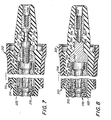
- FIGS. 5 and 6 a forward portion of another female electrical connector element constructed in accordance with the invention is shown in the form of a forward portion of bushing insert 110.
- Bushing insert 110 is similar to the above-described bushing insert 10 in that a housing 112 includes an outer housing casing 114 with inner and outer portions 116 and 118 of insulating and conductive elastomeric materials, respectively, and a rigid, metallic inner tubular housing member 120.
- a tubular insulating nosepiece 132 is threaded into housing member 120 and has a forward end 136.
- a tubular carrier member 140 includes a piston 146 unitary therewith and received within a cylindrical inner surface 148 of the housing member 120.
- a female contact element 150 is threaded into the carrier member 140 so that the carrier member 140, the piston 146 and the female contact element 150 all are parts of an axially movable female contact assembly 170.
- a kinetic energy absorption and dissipation means includes a shearing ring 172 affixed to the inner housing member 120, as in the earlier-described embodiment, and a stop shoulder 176 at the forward end of the piston 146.
- a shearable structure is provided on the outer surface 178 of the carrier member 140 and, as before, includes a primary shearable structure in the form of a shearable ring 180 located adjacent the forward end of the carrier member 140. In this instance, however, a secondary shearable structure is in the form of a tapered portion 182 located on the carrier member 140 axially between the shearable ring 180 and stop shoulder 176 of piston 146.
- the tapered portion 182 extends from an axially-forward smaller radius at 183 rearwardly to an axially-rearward larger radius at 184.
- a slight undercut is provided at 196, between the shearable ring 180 and the stop shoulder 176 so as to facilitate the venting of excessive arc-quenching gases through vent ports 194 and passage 192 after seals 190 pass beyond the forward end 136 of tubular nosepiece 132.
- FIG. 7 illustrates fragmented portions of another bushing insert 210 constructed in accordance with the invention.
- the most forward portion of bushing insert 210 which is not illustrated in FIG. 7, may be constructed essentially the same as the forward portion of the bushing inserts 10 and 110 described above.
- the arrangement wherein a housing 212 includes an outer housing casing 214 of elastomeric materials and a rigid, metallic, electrically conductive inner housing member 220 having a forward end 222 and a rearward end 224 with a threaded aperture 226 at the rearward end 224 is the same as that of either bushing insert 10 or bushing insert 110.
- threaded stud 228 which is received within threaded apezture 226 is a part of a metallic, electrically conductive extension 230 which, in addition to providing a further threaded aperture 232 at the remote end 234 thereof for attachment to a high voltage circuit, such as the terminal of a transformer (not shown), includes kinetic energy absorption and dissipation means as follows.
- extension 230 includes an axially-extending portion in the form of neck 236 provided with a predetermined transverse cross-sectional area, as at 238, which will enable neck 236 to become permanently deformed through axial elongation in response to an axially directed force of sufficient magnitude applied to neck 236.
- bushing insert 210 includes a carrier member 240 having a piston 246 received within the inner surface 248 of inner housing member 220.
- the carrier member 240 is movable within the inner housing member 220 between a retracted location, wherein the piston 246 is at the rearward end 224 of the inner housing member 220, and an advanced location, wherein the carrier member 24Q, and the female oontact assembly 270 of which carrier member 240 is a part, is located adjacent the forward end 222 of the inner housing member 220 with a stop shoulder 276 on the piston 246 coupled with a stop ring 272 affixed to the inner housing member 220 to confine the carrier member 240 within the inner housing member 220.
- the pre- cross-sectional area at 238 is chosen, along with the appropriate axial length of neck 236, so that enough of the kinetic energy of the female contact assembly 270 will be absorbed and dissipated upon the impact resulting from the coupling of stop shoulder 276 with stop ring 272 to preclude a catastraphic failure in the bushing insert 210.
- Bushing insert 310 also is similar to the earlier-described embodiment in that a housing 312 includes an outer housing casing 314 of elastomeric materials and a rigid, metallic, electrically conductive inner housing member 320 L which extends longitudinally between a forward end 322 and a rearward end 324 within outer housing casing 314.
- the construction of inner housing member 320 differs, however, from that of the corresponding component part of the aforesaid embodiments in that a reaward extension.330 is unitary with the inner housing member 320 at the rearward end 324.
- a blind hole 332 is located in the extension 330, a portion of which is threaded at 334 for attachment to a high voltage circuit.
- Blind hole 332 extends forward beyond the threaded portion 334 to establish a tubular neck 336 in the extension 330 between the rearward end 324 of the inner housing member 320 and the threaded portion 334.
- Tubular neck 336 is provided with a carefully chosen predetermined cross-sectional area, as at 338, along with the. appropriate axial length, for purposes which will be more fully described below.
- Carrier member 340 and piston 346 thereof are parts of a female contact assembly 370 similar to the corresponding female contact assemblies of the above bushing inserts 10, 110 and 210.
- a stop member in the form of stop ring 372 is affixed to the innex housing member 320 and a stop shoulder 374 is located on piston 346.
- tubular neck 336 thus serves to absorb and dissipate a sufficient amount of the kinetic energy of female contact assembly 370 to preclude failure of the bushing insert 10, as well as failure of the connection, at threaded portion 334, with the high voltage circuit.
- the tubular neck 336 provides the advantage of making available higher torsional strength for the predetermined cross-sectional area 338 when the bushing insert 10 is assembled with the terminal of the high voltage circuit.
- bushing inserts 10 and 110 may include a permanently deformable neck 236 in the respective extensions 30 and 130 to supplement the material shearing arrangements of those bushing inserts in absorbing and dissipating kinetic energy, but need not include such a supplementary kinetic energy absorption and dissipation means.
- the permanently deformable neck 236 of bushing insert 210 may be employed as the sole kinetic energy absorption and dissipation means in bushing insert 210 or may be supplemented by the material shearing means disclosed in connection with the description of bushing inserts 10 and 110.
- the tubular neck 336 of rearward extension 330 in bushing insert 310 may serve as the sole means for absorbing and dissipating kinetic energy or may be supplemented by the material shearing means disclosed in the earlier-described embodiments.
Landscapes
- Connector Housings Or Holding Contact Members (AREA)
- Circuit Breakers (AREA)
Priority Applications (2)
| Application Number | Priority Date | Filing Date | Title |
|---|---|---|---|
| DE8383300060T DE3373242D1 (en) | 1983-01-06 | 1983-01-06 | Electrical high voltage connector |
| EP19830300060 EP0113491B1 (de) | 1983-01-06 | 1983-01-06 | Elektrischer Hochspannungsverbinder |
Applications Claiming Priority (1)
| Application Number | Priority Date | Filing Date | Title |
|---|---|---|---|
| EP19830300060 EP0113491B1 (de) | 1983-01-06 | 1983-01-06 | Elektrischer Hochspannungsverbinder |
Publications (2)
| Publication Number | Publication Date |
|---|---|
| EP0113491A1 true EP0113491A1 (de) | 1984-07-18 |
| EP0113491B1 EP0113491B1 (de) | 1987-08-26 |
Family
ID=8191025
Family Applications (1)
| Application Number | Title | Priority Date | Filing Date |
|---|---|---|---|
| EP19830300060 Expired EP0113491B1 (de) | 1983-01-06 | 1983-01-06 | Elektrischer Hochspannungsverbinder |
Country Status (2)
| Country | Link |
|---|---|
| EP (1) | EP0113491B1 (de) |
| DE (1) | DE3373242D1 (de) |
Cited By (1)
| Publication number | Priority date | Publication date | Assignee | Title |
|---|---|---|---|---|
| WO2006074138A1 (en) * | 2005-01-04 | 2006-07-13 | Cooper Technologies Company | Separable insulated connector and method |
Citations (5)
| Publication number | Priority date | Publication date | Assignee | Title |
|---|---|---|---|---|
| US3539972A (en) * | 1968-05-21 | 1970-11-10 | Amerace Esna Corp | Electrical connector for high voltage electrical systems |
| US3542986A (en) * | 1968-02-23 | 1970-11-24 | Gen Electric | Quick-make,quick-break actuator for high voltage electrical contacts |
| US4068913A (en) * | 1975-09-03 | 1978-01-17 | Amerace Corporation | Electrical connector apparatus |
| US4099155A (en) * | 1976-11-10 | 1978-07-04 | Rte Corporation | Gas actuated high voltage bushing |
| US4186985A (en) * | 1978-08-29 | 1980-02-05 | Amerace Corporation | Electrical connector |
-
1983
- 1983-01-06 DE DE8383300060T patent/DE3373242D1/de not_active Expired
- 1983-01-06 EP EP19830300060 patent/EP0113491B1/de not_active Expired
Patent Citations (5)
| Publication number | Priority date | Publication date | Assignee | Title |
|---|---|---|---|---|
| US3542986A (en) * | 1968-02-23 | 1970-11-24 | Gen Electric | Quick-make,quick-break actuator for high voltage electrical contacts |
| US3539972A (en) * | 1968-05-21 | 1970-11-10 | Amerace Esna Corp | Electrical connector for high voltage electrical systems |
| US4068913A (en) * | 1975-09-03 | 1978-01-17 | Amerace Corporation | Electrical connector apparatus |
| US4099155A (en) * | 1976-11-10 | 1978-07-04 | Rte Corporation | Gas actuated high voltage bushing |
| US4186985A (en) * | 1978-08-29 | 1980-02-05 | Amerace Corporation | Electrical connector |
Cited By (2)
| Publication number | Priority date | Publication date | Assignee | Title |
|---|---|---|---|---|
| WO2006074138A1 (en) * | 2005-01-04 | 2006-07-13 | Cooper Technologies Company | Separable insulated connector and method |
| US7134889B2 (en) | 2005-01-04 | 2006-11-14 | Cooper Technologies Company | Separable insulated connector and method |
Also Published As
| Publication number | Publication date |
|---|---|
| DE3373242D1 (en) | 1987-10-01 |
| EP0113491B1 (de) | 1987-08-26 |
Similar Documents
| Publication | Publication Date | Title |
|---|---|---|
| US4600260A (en) | Electrical connector | |
| JPS6232583B2 (de) | ||
| US5525069A (en) | Electrical Connector | |
| US4068913A (en) | Electrical connector apparatus | |
| CN100440633C (zh) | 具有活塞接触元件的电连接器 | |
| US4260214A (en) | Fault-closable electrical connector | |
| US5393240A (en) | Separable loadbreak connector | |
| US7632120B2 (en) | Separable loadbreak connector and system with shock absorbent fault closure stop | |
| US7811109B2 (en) | Separable loadbreak connector with a conductive tube and a conductive piston | |
| US3930709A (en) | Electrical connector | |
| US4192572A (en) | Electrical connector apparatus | |
| US4170394A (en) | High voltage separable connector system with modified dwell position | |
| EP0113491B1 (de) | Elektrischer Hochspannungsverbinder | |
| US4199213A (en) | Method of constructing an electrical connector switching module | |
| CA1064127A (en) | Contact assembly separable during energization of a high voltage circuit therethrough | |
| CA1043000A (en) | Electrical connector apparatus | |
| CN215070609U (zh) | 牵引器用电气连接自密封插头 | |
| KR102308825B1 (ko) | 가스절연개폐장치 | |
| TWI387166B (zh) | 可分離的負載啟斷連接器及系統 |
Legal Events
| Date | Code | Title | Description |
|---|---|---|---|
| PUAI | Public reference made under article 153(3) epc to a published international application that has entered the european phase |
Free format text: ORIGINAL CODE: 0009012 |
|
| AK | Designated contracting states |
Designated state(s): BE DE FR GB IT NL SE |
|
| 17P | Request for examination filed |
Effective date: 19841231 |
|
| 17Q | First examination report despatched |
Effective date: 19860226 |
|
| GRAA | (expected) grant |
Free format text: ORIGINAL CODE: 0009210 |
|
| AK | Designated contracting states |
Kind code of ref document: B1 Designated state(s): BE DE FR GB IT NL SE |
|
| REF | Corresponds to: |
Ref document number: 3373242 Country of ref document: DE Date of ref document: 19871001 |
|
| ITF | It: translation for a ep patent filed | ||
| ET | Fr: translation filed | ||
| PLBE | No opposition filed within time limit |
Free format text: ORIGINAL CODE: 0009261 |
|
| STAA | Information on the status of an ep patent application or granted ep patent |
Free format text: STATUS: NO OPPOSITION FILED WITHIN TIME LIMIT |
|
| 26N | No opposition filed | ||
| PG25 | Lapsed in a contracting state [announced via postgrant information from national office to epo] |
Ref country code: GB Effective date: 19890106 |
|
| PG25 | Lapsed in a contracting state [announced via postgrant information from national office to epo] |
Ref country code: SE Effective date: 19890107 |
|
| PG25 | Lapsed in a contracting state [announced via postgrant information from national office to epo] |
Ref country code: BE Effective date: 19890131 |
|
| BERE | Be: lapsed |
Owner name: AMERACE CORP. Effective date: 19890131 |
|
| PG25 | Lapsed in a contracting state [announced via postgrant information from national office to epo] |
Ref country code: NL Effective date: 19890801 |
|
| NLV4 | Nl: lapsed or anulled due to non-payment of the annual fee | ||
| GBPC | Gb: european patent ceased through non-payment of renewal fee | ||
| PG25 | Lapsed in a contracting state [announced via postgrant information from national office to epo] |
Ref country code: FR Free format text: LAPSE BECAUSE OF NON-PAYMENT OF DUE FEES Effective date: 19890929 |
|
| PG25 | Lapsed in a contracting state [announced via postgrant information from national office to epo] |
Ref country code: DE Effective date: 19891003 |
|
| REG | Reference to a national code |
Ref country code: FR Ref legal event code: ST |
|
| EUG | Se: european patent has lapsed |
Ref document number: 83300060.7 Effective date: 19891204 |