EP0113560A1 - Viscosimètre à pont de capillaires - Google Patents
Viscosimètre à pont de capillaires Download PDFInfo
- Publication number
- EP0113560A1 EP0113560A1 EP83307523A EP83307523A EP0113560A1 EP 0113560 A1 EP0113560 A1 EP 0113560A1 EP 83307523 A EP83307523 A EP 83307523A EP 83307523 A EP83307523 A EP 83307523A EP 0113560 A1 EP0113560 A1 EP 0113560A1
- Authority
- EP
- European Patent Office
- Prior art keywords
- fluid flow
- capillary
- flow circuit
- capillaries
- solvent
- Prior art date
- Legal status (The legal status is an assumption and is not a legal conclusion. Google has not performed a legal analysis and makes no representation as to the accuracy of the status listed.)
- Granted
Links
- 239000012530 fluid Substances 0.000 claims abstract description 135
- 239000007788 liquid Substances 0.000 claims abstract description 116
- 239000002904 solvent Substances 0.000 claims abstract description 86
- 239000000243 solution Substances 0.000 claims description 33
- 229920000642 polymer Polymers 0.000 claims description 12
- 238000011144 upstream manufacturing Methods 0.000 claims description 12
- 238000000034 method Methods 0.000 claims description 11
- 238000010276 construction Methods 0.000 claims description 6
- 239000012527 feed solution Substances 0.000 claims 2
- 238000000151 deposition Methods 0.000 claims 1
- 210000001736 capillary Anatomy 0.000 description 96
- 239000012488 sample solution Substances 0.000 description 17
- 239000000523 sample Substances 0.000 description 15
- 238000004458 analytical method Methods 0.000 description 5
- 230000004048 modification Effects 0.000 description 4
- 238000012986 modification Methods 0.000 description 4
- 238000002156 mixing Methods 0.000 description 3
- 239000012086 standard solution Substances 0.000 description 3
- 239000002699 waste material Substances 0.000 description 3
- IJGRMHOSHXDMSA-UHFFFAOYSA-N Atomic nitrogen Chemical compound N#N IJGRMHOSHXDMSA-UHFFFAOYSA-N 0.000 description 2
- 230000008602 contraction Effects 0.000 description 2
- 230000035945 sensitivity Effects 0.000 description 2
- 229920001169 thermoplastic Polymers 0.000 description 2
- CTQNGGLPUBDAKN-UHFFFAOYSA-N O-Xylene Chemical compound CC1=CC=CC=C1C CTQNGGLPUBDAKN-UHFFFAOYSA-N 0.000 description 1
- 238000003795 desorption Methods 0.000 description 1
- 238000007865 diluting Methods 0.000 description 1
- 238000006073 displacement reaction Methods 0.000 description 1
- 238000002474 experimental method Methods 0.000 description 1
- 239000007789 gas Substances 0.000 description 1
- 238000005259 measurement Methods 0.000 description 1
- 229910052757 nitrogen Inorganic materials 0.000 description 1
- 229920005990 polystyrene resin Polymers 0.000 description 1
- 230000001681 protective effect Effects 0.000 description 1
- 230000000717 retained effect Effects 0.000 description 1
- 229910001220 stainless steel Inorganic materials 0.000 description 1
- 239000010935 stainless steel Substances 0.000 description 1
- 239000008096 xylene Substances 0.000 description 1
Images

Classifications
-
- G—PHYSICS
- G01—MEASURING; TESTING
- G01N—INVESTIGATING OR ANALYSING MATERIALS BY DETERMINING THEIR CHEMICAL OR PHYSICAL PROPERTIES
- G01N11/00—Investigating flow properties of materials, e.g. viscosity, plasticity; Analysing materials by determining flow properties
- G01N11/02—Investigating flow properties of materials, e.g. viscosity, plasticity; Analysing materials by determining flow properties by measuring flow of the material
- G01N11/04—Investigating flow properties of materials, e.g. viscosity, plasticity; Analysing materials by determining flow properties by measuring flow of the material through a restricted passage, e.g. tube, aperture
- G01N11/08—Investigating flow properties of materials, e.g. viscosity, plasticity; Analysing materials by determining flow properties by measuring flow of the material through a restricted passage, e.g. tube, aperture by measuring pressure required to produce a known flow
-
- G—PHYSICS
- G01—MEASURING; TESTING
- G01N—INVESTIGATING OR ANALYSING MATERIALS BY DETERMINING THEIR CHEMICAL OR PHYSICAL PROPERTIES
- G01N30/00—Investigating or analysing materials by separation into components using adsorption, absorption or similar phenomena or using ion-exchange, e.g. chromatography or field flow fractionation
- G01N30/02—Column chromatography
- G01N30/62—Detectors specially adapted therefor
- G01N2030/621—Detectors specially adapted therefor signal-to-noise ratio
- G01N2030/625—Detectors specially adapted therefor signal-to-noise ratio by measuring reference material, e.g. carrier without sample
-
- G—PHYSICS
- G01—MEASURING; TESTING
- G01N—INVESTIGATING OR ANALYSING MATERIALS BY DETERMINING THEIR CHEMICAL OR PHYSICAL PROPERTIES
- G01N30/00—Investigating or analysing materials by separation into components using adsorption, absorption or similar phenomena or using ion-exchange, e.g. chromatography or field flow fractionation
- G01N30/02—Column chromatography
-
- G—PHYSICS
- G01—MEASURING; TESTING
- G01N—INVESTIGATING OR ANALYSING MATERIALS BY DETERMINING THEIR CHEMICAL OR PHYSICAL PROPERTIES
- G01N30/00—Investigating or analysing materials by separation into components using adsorption, absorption or similar phenomena or using ion-exchange, e.g. chromatography or field flow fractionation
- G01N30/02—Column chromatography
- G01N30/26—Conditioning of the fluid carrier; Flow patterns
- G01N30/28—Control of physical parameters of the fluid carrier
- G01N30/32—Control of physical parameters of the fluid carrier of pressure or speed
Definitions
- the invention relates to capillary bridge viscometers useful for measuring the relative viscosity of a solute in solution with a solvent for said solute.
- a common method employed to obtain information respecting molecular weights of solvent soluble thermoplastic polymers is to measure the viscosity of dilute solutions of such polymers in a suitable solvent. From the knowledge of the viscosity of such dilute solution and the known viscosity of the solvent employed in such determinations, it is possible to obtain data respecting the relative viscosity, specific viscosity, and inherent viscosity of such thermoplastic polymers.
- apparatus which has the capability of accurately measuring the viscosity of a dilute solution of a solute in a solvent therefor.
- This apparatus comprises a bridge containing two fluid flow circuits.
- the first circuit includes in series, two capillaries.
- the second circuit includes, in sequence in the fluid flow stream: (a) a first capillary; (b) a liquid reservoir having a liquid volume substantially larger than the volume of said first capillary, and including a liquid inlet and a liquid outlet connectable with the second fluid circuit; (c) a second capillary; and (d) valving means which selectively feeds the liquid exiting the first capillary directly into the second capillary or into the liquid reservoir.
- the apparatus further includes a liquid inlet line which feeds both the first and second fluid flow circuits.
- Means is provided for measuring the gauge pressure in the viscometer at any point upstream of the second capillary in either the first or second fluid flow circuits.
- means is provided for measuring the differential pressure existing between (1) a point intermediate of the capillaries in the first fluid flow circuit, and (2) a point intermediate of the capillaries in the second fluid flow circuit. The lengths and diameters of the capillaries are selected so that essentially no pressure differential is established between the two fluid flow circuits when a common fluid is flowing through all of the capillaries.
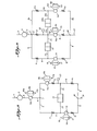
- the apparatus includes a solvent reservoir 5 which is connected through line 6 to a junction point 7 in the bridge circuit.
- Line 4 is connected to a source of constant pressure gas such as nitrogen at 5-10 psi which drives the solvent from reservoir 5 through the bridge.
- the first fluid circuit includes a line 8 which runs from junction point 7 to junction point 20 and includes therein, in series, capillary 12 and capillary 14.
- the second fluid flow circuit includes a line 9 which runs from junction point 7 to junction point 20.
- Line 21 is connected to junction point 20 and discharges the fluid being fed through the bridge.
- the second fluid circuit includes, in sequence in the fluid flow stream, a first capillary 11, valving means 15, and a second capillary 13.
- a pressure gauge 25 is included in the bridge to measure gauge pressure 8, or 9, provided only that it is upstream from capillary 13 or capillary 14.
- a differential pressure transducer 22 is connected across the two fluid flow circuits of the bridge by lines 23 and 24 to measure the differential pressure developed across the bridge when two different fluids are flowing through the capillaries in the bridge as subsequently described in greater detail.
- a line 26 having a valve 27 therein is connected across lines 23 and 24.
- FIG. 2 illustrates the operation of valving means 15 and associated liquid reservoir 18 included in Fig. 1.
- Valving means 15. is a two-position 6-port valve of the type commercially available from commercial sources such as VALCO Instruments, Inc., of Houston, Texas.
- Liquid reservoir 18 is a vertically aligned wide-bore column which typically will have a 0.25" O.D., be about 1' long, and have an internal volume of about 4.0 ml.
- Valve 15 has six (6) ports 31, 32, 33, 34, 35, and 36. Valve 15 also has six (6) internal arcuate lines 41, 42, and 43 which are shown as solid lines and 44, 45, and 46 which are shown as dotted lines. As illustrated, in the valve's first operating position, line 41 connects to ports 31 and 32; line 42 connects to ports 33 and 34; and line 43 connects to ports 35 and 36. In the first operating position, lines 44, 45, and 46 are not fluidly connected to any of the ports. In the valve's second operating position, line 44 connects to ports 31 and 36; line 45 connects to ports 35 and 34; and line 46 connects to ports 33 and 32. Port 36 is connected by line 16 to the top of liquid reservoir 18. Port 33 is connected by line 17 to the bottom of liquid reservoir 18. Wherever subsequently used, the terms "first position" (or “first operating position”) and "second position" (or “second operating position”) will have the same meaning as discussed above.
- valve means 15 is set in its first operating position in which line 41 connects to ports 31 and 32.
- Port 31 will be connected to receive fluid exiting capillary 11.
- Port 32 will be connected to feed fluid from valving means 15 to capillary 13.
- Liquid reservoir 18 will be loaded with the sample solution by injecting the sample through open port 34. The sample flows through arcuate line 42, exits port 33, flows through line 17, fills reservoir 18, flows through line 16, enters port 36, flows through arcuate line 43 and exits port 35 to a waste line (not shown).
- a valve (not shown) in line 4 is opened to start a flow of solvent through the bridge.
- the solvent flows through the first circuit which includes line 8 and capillaries 12 and 14.
- the solvent flowing through the second circuit after discharge from capillary 11, enters valving means 15 through port 31.
- the solvent flows through arcuate line 41 and exits via port 32. It then flows through capillary 13.
- Solvent from both circuits is discharged through line 21.
- Valve 27 is kept in an open position until the entire bridge is filled with solvent and solvent is discharged through line 21. Valve 27 then is closed. At this time, both circuits, including capillaries 11, 12, 13, and 14, are filled with solvent.
- the flow rate through both circuits is identical and no pressure differential is detected by the transducer 22.
- the valving means 15 then is switched to its second operating position in which line 44 connects to ports 31 and 36.
- the solvent entering port 31 now flows through arcuate line 44, exits through port 36, and flows through line 16 into the top of liquid reservoir 18.
- the solvent entering the liquid reservoir displaces the sample solution contained therein.
- the displaced sample solution flows through line 17, valve port 33, arcuate line 46, and valve port 32 to enter line 9 and capillary 13.
- the valving means 15 then is switched back to its first operating position in which solvent flows through all of the capillaries.
- the liquid reservoir 18 then is filled with a second sample solution as previously described.
- the apparatus then is ready to measure the viscosity of the second sample.
- the liquid reservoir will be mounted in a vertical plane.
- the other elements of the two fluid flow circuits can be mounted in either a vertical or horizontal plane.
- Fig. 4 illustrates a modification of the embodiment of the invention illustrated in Fig. 1.
- the embodiment of Fig. 4 is identical with the embodiment of Fig. 1 with the single exception that a second valving means 15a and an associated liquid reservoir 18a are included in the first fluid flow circuit intermediate of capillary 12 and capillary 14.
- the construction of 15a is identical to that of 15.
- the construction of 18a is identical to that of 18.
- Reservoir 18a is connected to the ports of 15a in the same manner illustrated in Fig. 2.
- the valving means 15a is set in its second operating position so that the solvent, after entering the valving means 15a, flows through reservor 18a before flowing into capillary 14.
- any minor changes in temperature which would cause a difference in pressure by expansion or contraction of the sample in liquid reservoir 18 are compensated for and offset by a compensating like expansion or contraction of the solvent in the second liquid reservoir 18a.
- the sensitivity of the apparatus of Fig. 4 can be increased by initially setting valving means l5a in its first operating position, i.e., with arcuate line 41 connecting to ports 31 and 32. While the valving means is in this position, liquid reservoir 18a can be filled with a standard solution having a known viscosity. When valving means 15 is switched to its second operating position, valving means 15a also will be switched to its second operating position. When valving means 15 and l5a are both set in their second operation position, capillaries 11 and 12 both will be filled with solvent. Capillary 13 will be filled with the solution containing the solute of unknown relative viscosity which is to be determined in the experiment.
- capillary 14 will be filled with the standard solution whose viscosity is known.
- the pressure differential set up across the bridge and measured by differential pressure transducer 22 will ' measure the difference in relative viscosity of the two solutions contained in capillaries 13 and 14.
- the method of calculating the relative viscosity of the solute in the unknown sample will be described subsequently.
- Fig. 5 illustrates another modification of the apparatus of the invention having somewhat greater flexibility in mode of operation than the embodiment illustrated in Fig. 1.
- the embodiment of Fig. 5 differs from the embodiment of Fig. 1 in two respects.
- a valving means 15b and an associated liquid reservoir 18b are included in line 6 intermediate of the solvent reservoir 5 and junction point 7.
- the connections of lines 16b and 17b to the valving means 15b are the same as shown in Fig. 2.
- Second, a third valving means 15c and an associated liquid reservoir 18c are included in the first circuit upstream of capillary 12.
- the connections of lines 16c and 17c to valving means 15c are as shown in Fig. 3.
- valving means 15b is set in its first operating position so as to feed solvent to both of the fluid flow circuits.
- valving means 15c will be set in its first operating position so as to feed only solvent to capillaries 12 and 14.
- Liquid reservoir 18 will be charged with sample solution in the manner previously described.
- Valving means 15 then will be set in its second operating position. The solvent, after flowing through capillary 11, enters liquid reservoir 18 and displaces the sample solution which then flows through capillary 13. As capillaries 11, 12, and 14 are filled with solvent, a pressure differential will be established across the bridge and will be detected by differential pressure transducer 22.
- Valving means 15 and 15c are set in their second operating position.
- Valving means 15b is set in its first operating position and liquid reservoir 18b is filled with the sample solution.
- Solvent is passed through the bridge to fill capillaries 11, 13, 12, and 14 and liquid reservoirs 18 and 18c with solvent.
- Valving means 15b then is set to its second operating position to feed solvent into liquid reservoir 18b. The solvent displaces the sample solution which then is fed to the bridge.
- the sample entering the first circuit enters liquid reservoir 18c and displaces the stored solvent which then flows through capillaries 12 and 14.
- the sample entering the second circuit flows through capillary 11 and enters liquid reservoir 18 to displace solvent which flows through capillary 13.
- solvent flowing through capillaries 12, 14, and 13 and solution flowing through capillary 11 a pressure differential will be established across the bridge and will be detected by the transducer 22.
- yalving means 15b is returned to its first operating position to feed solvent to the bridge.
- a second sample is charged to liquid reservoir 18b.
- Valving means 15 and 15c are set to their first operating positions so that solvent flowing through valving means 15 and 15c does not flow through the associated liquid reservoirs 18 and 18c.
- solvent is fed through port 34 and flows through arcuate line 42, port 33 and line 16 to enter the top of the liquid reservoir. This action displaces unused solution which flows through line 17, port 36, arcuate line 43 and port 35 to a waste line not shown.
- Valving means 15 and 15c then are returned to their second operating position and the apparatus is in a condition to measure the relative viscosity of the second sample.
- the apparatus illustrated in Fig. 6 consists of two ganged bridge circuits sharing a common first fluid flow circuit.
- the first fluid flow circuit includes line 8 having therein, in series, first capillary 12, valving means 15a with associated liquid reservoir 18a, and second capillary 14.
- the first fluid flow circuit runs from junction point 7 to junction point 20.
- the second fluid flow circuit of the first bridge includes line 9 containing therein, in sequence in the flow stream, first capillary 11, valving means 15, and associated liquid reservoir 18, and second capillary 13.
- the second fluid flow circuit of the bridge runs from junction point 7 to junction point 20.
- Differential pressure transducer 22 measures any pressure differential existing between the first and second fluid flow circuits in the first bridge.
- the second fluid flow circuit of the second bridge includes line 9a containing therein, in sequence in the flow stream, first capillary lla, valving means 15d with its associated liquid reservoir 18d, and second capillary 13a.
- the second fluid flow circuit of the second bridge runs from junction point 7 to junction point 20.
- Transducer 22a measures any pressure differential existing between the first and second fluid flow circuits in the second bridge.
- the apparatus of Fig. 6 can be operated in essentially the same manner as the apparatus of Fig. 4.
- Each of valving means 15, 15a, and 15d will be connected to the liquid reservoirs 18, 18a and 18d as shown in Fig. 2.
- Valving means 15 and 15d will be set in their first operating position and the liquid reservoirs will be filled with samples as previously described.
- Valving means 15a will be set in its second operating position. Solvent is fed to the two ganged bridges and fills each of capillaries 11, 13, 12, 14, lla and 13a and liquid reservoir 18a with solvent.
- Valving means 15 and 15d then are set to their second operating positions.
- Solvent entering liquid reservoir 18 displaces stored sample solution which then flows through capillary 13.
- a pressure differential is detected by trans- transducer 22 and recorded.
- solvent entering liquid reservoir 18d displaces the second solution which then flows through capillary 13a.
- a pressure differential is detected by transducer 22a and is recorded.
- Valving means 15 and 15d can be retained in their first operating position until both transducers 22 and 22a show zero pressure differentials.
- liquid reservoirs 18 and 18d contain only solvent.
- the valving means then are switched to their first operating positions and the liquid reservoirs are filled with fresh samples as previously described.
- valving means 15 and 15d can be immediately switched to their first operating positions.
- Fresh samples then are injected into liquid reservoirs 18 and 18d. An excess of the fresh samples should be passed through the reservoirs to assure that there will be no mixing of the samples in the reservoirs.
- the two ganged bridges measure the samples' relative viscosities simultaneously.
- the average analysis time can be reduced by carrying out the analyses in sequence rather than simultaneously.
- valving means 15 will be switched to its second operating position as soon as liquid reservoir 18 is charged with sample. While the data for the first sample are being obtained, the operator will be charging liquid reservoir 18d with the second sample. By charging the liquid reservoirs in sequence while data are being obtained for the other sample, it is apparent that more analyses can be obtained per unit of time.
- the apparatus of Fig. 1 can be employed cooperatively with a gel permeation chromatograph (GPC) to obtain detailed information on the molecular weight distribution of a polymer.
- the polymer of interest will be deposited on the sorbant in the conventional manner.
- the sorbed polymer will be eluted with an eluting solvent.
- the eluant will be passed through a first detector to measure a parameter of interest, usually refractive index.
- the eluant then will be fed to the bridge of Fig. 1.
- the bridge and liquid reservoir 18 previously will have been filled with the eluting solvent.
- Valving means 15 will be connected to liquid reservoir 18 as shown in Fig. 3 and will be set in its second operating position.
- the transducer will continuously record a pressure differential as capillary 13 will continuously be filled with the eluting solvent, while the other capillaries 11, 12, and 14 will be filled with eluant.
- the measured pressure differential will change con- 1 tinuously as the molecular weight of the eluted solute polymer changes by the desorption process taking place on the gel.
- Fig. 5 can be used in a similar manner by first filling both liquid reservoirs 18 and 18c with the eluting solvent.
- capillaries 13, 12, and 14 will be filled with solvent and capillary 11 will be filled with the eluant.
- the drawings shown are schematic flow sheets which illustrate the operating principles of the apparatus of the invention.
- Lines 8 and 9 shown in Figs. 1, 4, 5, and 6 are very short and in some circumstances can be dispensed with entirely.
- the junction point 7 can be a simple "Tee” connector which connects line 6 to capillaries 11 and 12.
- junction point 20 can be a simple "Tee” connector which connects capillaries 13 and 14 to waste line 21.
- the fluid connection between capillary 11, port 31 of valving means 15 and line 23, can be a simple "Tee.”
- the fluid connection between port 32 of valving means 15 and capillary 13 can be a simple line connector.
- the fluid connection between capillary 12, line 24, capillary 14 and pressure gauge 25 can be a simple two-line connector.
- the pressure gauge 25 can be included at any point in the bridge upstream of either capillary 13 or 14. Its position affects the calculations and the calculations subsequently set forth are made with the gauge 25 being in the position shown in Fig.
- Each capillary will have approximately the same length. Typically, each capillary will be about 5 feet long and have an I.D. of about 0.01 inch. As the measurement of the pressure differential is made across the bridge at points intermediate of the capillaries in each fluid flow circuit of the bridge, knowledge of the precise length of the capillaries is not required for calculation of the relative viscosity of the solute. Each set of capillaries will be selected and tested so that no pressure differential is measured when a common fluid is flowing through each of the capillaries in the bridge.
- the liquid reservoir(s) will be mounted in a vertical plane to assure plug flow therethrough.
- the connections of the liquid reservoir to the ports of the valving means will be as shown in Fig. 2 when a sample solution is stored in the reservoir and less dense solvent is to be introduced into the top of the reservoir to displace the sample solution.
- the connections to the valving means will be set as shown in Fig. 3 to introduce the denser sample solution in the bottom of the reservoir. Whenever it is necessary to flush residual sample solution from a liquid reservoir, it is highly desirable to introduce solvent in the top of the reservoir to avoid mixing and diluting the residual sample solution.
- the pressure differential measured across the bridge by differential pressure transducer 22 is defined by equation 1. where: P 2 is the pressure measured intermediate of the capillaries in the second fluid flow circuit, and P 1 is the pressure measured intermediate of the capillaries in the first fluid flow circuit.
- each capillary was 12 ft. long and had an I.D. of 0.02 inch.
- the liquid reservoir was 1 ft. long, had an O.D. of 0.25" and an internal volume of 4 ml. All connection and capillaries were fabricated from stainless steel.
- the transducer diaphragm was rated to handle a differential pressure of 1 psi.
- a polystyrene resin of known intrinsic viscosity (0.464) was dissolved in xylene to prepare a solution containing 0.20 gram/deciliter.
- Duplicate runs were made in one day employing a gauge pressure of 5.7 psi.
- the measured specific viscosity values were 0.0087 and 0.0088.
- the following day another set of duplicate runs were made employing a gauge pressure of 9.1 psi.
- the measured specific viscosity values were 0.0087 and 0.0089.
Landscapes
- Physics & Mathematics (AREA)
- Health & Medical Sciences (AREA)
- Life Sciences & Earth Sciences (AREA)
- Chemical & Material Sciences (AREA)
- Analytical Chemistry (AREA)
- Biochemistry (AREA)
- General Health & Medical Sciences (AREA)
- General Physics & Mathematics (AREA)
- Immunology (AREA)
- Pathology (AREA)
- Sampling And Sample Adjustment (AREA)
- Conductive Materials (AREA)
- Inorganic Insulating Materials (AREA)
- Agricultural Chemicals And Associated Chemicals (AREA)
- Measuring Fluid Pressure (AREA)
Applications Claiming Priority (2)
| Application Number | Priority Date | Filing Date | Title |
|---|---|---|---|
| US06/448,525 US4463598A (en) | 1982-12-10 | 1982-12-10 | Capillary bridge viscometer |
| US448525 | 1982-12-10 |
Publications (2)
| Publication Number | Publication Date |
|---|---|
| EP0113560A1 true EP0113560A1 (fr) | 1984-07-18 |
| EP0113560B1 EP0113560B1 (fr) | 1987-08-19 |
Family
ID=23780645
Family Applications (1)
| Application Number | Title | Priority Date | Filing Date |
|---|---|---|---|
| EP83307523A Expired EP0113560B1 (fr) | 1982-12-10 | 1983-12-09 | Viscosimètre à pont de capillaires |
Country Status (4)
| Country | Link |
|---|---|
| US (1) | US4463598A (fr) |
| EP (1) | EP0113560B1 (fr) |
| JP (1) | JPS59160740A (fr) |
| DE (1) | DE3373141D1 (fr) |
Cited By (4)
| Publication number | Priority date | Publication date | Assignee | Title |
|---|---|---|---|---|
| EP1152234A3 (fr) * | 2000-05-03 | 2004-01-02 | WGE Dr. Bures GmbH & Co. KG | Viscosimètre |
| US6708553B2 (en) | 2000-05-03 | 2004-03-23 | Wge Dr. Bures Gmbh & Co. Kg | Viscosimeter |
| US6877361B2 (en) * | 2001-04-30 | 2005-04-12 | Wge Dr. Bures Gmbh & Co. Kg | Viscosimeter |
| GB2420417A (en) * | 2004-10-15 | 2006-05-24 | Infra Scient Ltd | A capillary viscometer and method of measuring viscosity |
Families Citing this family (23)
| Publication number | Priority date | Publication date | Assignee | Title |
|---|---|---|---|---|
| JPS6196441A (ja) * | 1984-10-17 | 1986-05-15 | Idemitsu Kosan Co Ltd | 見掛粘度測定装置 |
| US4627271A (en) * | 1984-11-07 | 1986-12-09 | E. I. Du Pont De Nemours And Company | Differential pressure capillary viscometer for measuring viscosity independent of flow rate and temperature fluctuations |
| US4578990A (en) * | 1984-11-07 | 1986-04-01 | E. I. Du Pont De Nemours And Company | Differential pressure capillary viscometer for measuring viscosity independent of flow rate and temperature fluctuations |
| US4793174A (en) * | 1987-10-05 | 1988-12-27 | E. I. Du Pont De Nemours And Company | Differential pressure capillary viscometer |
| US4876882A (en) * | 1989-01-30 | 1989-10-31 | E. I. Du Pont De Nemours And Company | Viscosity detection method for liquid chromatography systems with carrier liquids having time-varying viscosity |
| CA2145599C (fr) * | 1995-03-27 | 2001-12-04 | David Wesley Forbes | Methode de controle continu de l'exactitude des resultats obtenus par un viscosimetre automatique |
| US5637790A (en) * | 1996-02-28 | 1997-06-10 | De Corral; Jose L. | Three capillary flow-through viscometer |
| US6076392A (en) * | 1997-08-18 | 2000-06-20 | Metasensors, Inc. | Method and apparatus for real time gas analysis |
| CA2362605A1 (fr) | 1999-02-25 | 2000-08-31 | Tadeusz M. Drzewiecki | Procedes et appareil d'analyse fluidique en temps reel |
| NL1015185C2 (nl) * | 2000-05-12 | 2001-11-13 | Stichting Tech Wetenschapp | Inrichting geschikt voor het meten van de viscositeit van een flu´dum. |
| US7213439B2 (en) * | 2005-03-28 | 2007-05-08 | Wyatt Technology Corporation | Automatic bridge balancing means and method for a capillary bridge viscometer |
| US7331218B2 (en) * | 2005-09-23 | 2008-02-19 | Wyatt Technology Corporation | Capillary bridge viscometer and method for measuring specific viscosity |
| CA2548931A1 (fr) * | 2006-05-11 | 2007-11-11 | The Fluid Life Corporation | Methode et dispositif permettant d'ameliorer la precision de capteurs optiques pour instruments a tubes capillaires |
| JP5200507B2 (ja) * | 2007-11-30 | 2013-06-05 | 東ソー株式会社 | 液体クロマトグラフ用粘度計 |
| US9759644B2 (en) | 2010-09-23 | 2017-09-12 | Malvern Instruments Incorporated | Balanced capillary bridge viscometer |
| IN2013MN00603A (fr) * | 2010-09-23 | 2015-05-29 | Malvern Instr Inc | |
| CN104502231B (zh) * | 2014-12-19 | 2017-04-19 | 西安交通大学 | 一种用于高温高压的双毛细管粘度计及其测试方法 |
| WO2017008062A1 (fr) * | 2015-07-08 | 2017-01-12 | Wyatt Technology Corporation | Viscosimètre différentiel à correction de compressibilité de solvant |
| US10712321B2 (en) | 2016-11-02 | 2020-07-14 | Wyatt Technology Corporation | Method to eliminate periodic noise from data collected with a chromatography system |
| US11965900B2 (en) | 2018-11-09 | 2024-04-23 | Wyatt Technology, Llc | Indicating a status of an analytical instrument on a screen of the analytical instrument |
| AU2019333836B2 (en) | 2019-01-02 | 2023-11-09 | Tosoh Corporation | Light scattering detectors and methods for the same |
| EP3695208B1 (fr) | 2019-01-02 | 2024-09-18 | Tosoh Corporation | Détecteurs de diffusion de lumière et cellules d'échantillon pour ceux-ci |
| JP7371850B2 (ja) * | 2019-06-20 | 2023-10-31 | 国立大学法人九州工業大学 | 粘度測定装置、表面張力測定装置、粘度測定方法および表面張力測定方法 |
Citations (4)
| Publication number | Priority date | Publication date | Assignee | Title |
|---|---|---|---|---|
| FR922204A (fr) * | 1945-12-21 | 1947-06-03 | Mach Automatiques Bardet | Procédé et dispositifs pour la mesure de la viscosité d'un fluide |
| US3334513A (en) * | 1964-05-15 | 1967-08-08 | Whirlpool Co | Gas analyzer |
| US3540264A (en) * | 1967-04-24 | 1970-11-17 | Rhodiaceta | Automatic viscometer |
| EP0065831A2 (fr) * | 1981-05-08 | 1982-12-01 | Agar Corporation N.V. | Procédé et dispositif de détermination de la viscosité d'un échantillon de fluide par comparaison à celle d'un fluide de référence |
Family Cites Families (4)
| Publication number | Priority date | Publication date | Assignee | Title |
|---|---|---|---|---|
| US3086386A (en) * | 1959-09-29 | 1963-04-23 | Standard Oil Co | Viscosity measuring system |
| US3808877A (en) * | 1972-09-18 | 1974-05-07 | Du Pont | Capillary viscometer |
| FR2268262B1 (fr) * | 1974-04-17 | 1976-12-17 | Ato Chimie | |
| SU805120A1 (ru) * | 1979-03-30 | 1981-02-15 | Украинский Институт Инженеровводного Хозяйства Научно-Произ-Водственного Объединения "Нефте-Химавтоматика" | Устройство дл измерени кинема-ТичЕСКОй В зКОСТи жидКОСТЕй |
-
1982
- 1982-12-10 US US06/448,525 patent/US4463598A/en not_active Expired - Lifetime
-
1983
- 1983-12-09 DE DE8383307523T patent/DE3373141D1/de not_active Expired
- 1983-12-09 EP EP83307523A patent/EP0113560B1/fr not_active Expired
- 1983-12-10 JP JP58233472A patent/JPS59160740A/ja active Granted
Patent Citations (4)
| Publication number | Priority date | Publication date | Assignee | Title |
|---|---|---|---|---|
| FR922204A (fr) * | 1945-12-21 | 1947-06-03 | Mach Automatiques Bardet | Procédé et dispositifs pour la mesure de la viscosité d'un fluide |
| US3334513A (en) * | 1964-05-15 | 1967-08-08 | Whirlpool Co | Gas analyzer |
| US3540264A (en) * | 1967-04-24 | 1970-11-17 | Rhodiaceta | Automatic viscometer |
| EP0065831A2 (fr) * | 1981-05-08 | 1982-12-01 | Agar Corporation N.V. | Procédé et dispositif de détermination de la viscosité d'un échantillon de fluide par comparaison à celle d'un fluide de référence |
Non-Patent Citations (1)
| Title |
|---|
| Soviet Inventions Illustrated week C 39, 8 November 1980 sections J 04, A 35, S 03 & SU-A-714236 * |
Cited By (4)
| Publication number | Priority date | Publication date | Assignee | Title |
|---|---|---|---|---|
| EP1152234A3 (fr) * | 2000-05-03 | 2004-01-02 | WGE Dr. Bures GmbH & Co. KG | Viscosimètre |
| US6708553B2 (en) | 2000-05-03 | 2004-03-23 | Wge Dr. Bures Gmbh & Co. Kg | Viscosimeter |
| US6877361B2 (en) * | 2001-04-30 | 2005-04-12 | Wge Dr. Bures Gmbh & Co. Kg | Viscosimeter |
| GB2420417A (en) * | 2004-10-15 | 2006-05-24 | Infra Scient Ltd | A capillary viscometer and method of measuring viscosity |
Also Published As
| Publication number | Publication date |
|---|---|
| DE3373141D1 (en) | 1987-09-24 |
| EP0113560B1 (fr) | 1987-08-19 |
| JPS59160740A (ja) | 1984-09-11 |
| JPH0333219B2 (fr) | 1991-05-16 |
| US4463598A (en) | 1984-08-07 |
Similar Documents
| Publication | Publication Date | Title |
|---|---|---|
| EP0113560B1 (fr) | Viscosimètre à pont de capillaires | |
| Haney | The differential viscometer. I. A new approach to the measurement of specific viscosities of polymer solutions | |
| US4520108A (en) | Method for continuous flow analysis of liquid sample | |
| EP0181224B1 (fr) | Viscosimètre de pression différentielle à tube capillaire pour mesurer la viscosité indépendamment de la vitesse d'écoulement et des fluctuations de température | |
| US5004538A (en) | Control arrangement for the chromatography of liquid | |
| US4019523A (en) | Method and apparatus for mixing gases | |
| US3911256A (en) | Apparatus for testing and analyzing fluid mixture | |
| CA1044040A (fr) | Procede d'analyse par chromatographie en phase liquide | |
| US7594428B2 (en) | Apparatus and method for eliminating the breakthrough peak in differential detectors | |
| US4286457A (en) | Viscosity measurement | |
| US4184359A (en) | Gas monitor for liquid flow line | |
| US4114419A (en) | Method of testing an analyzer to determine the accuracy thereof and a volumetric primary standard apparatus for doing same | |
| EP0250418A1 (fr) | Analyse de melanges multiphases | |
| CA1040454A (fr) | Methode et appareil d'analyse quantitative | |
| EP1949060B1 (fr) | Viscosimetre multicapillaire ameliore et procede | |
| Letot et al. | Performance evaluation of a continuous viscometer for high speed GPC | |
| US4728344A (en) | Polymer analysis | |
| JPH0221741B2 (fr) | ||
| GB2331978A (en) | A method and apparatus for taking liquid samples in a gas outlet pipe of a liquid/gas separator, fed with an oil well effluent | |
| US6708553B2 (en) | Viscosimeter | |
| US3176500A (en) | Measurement of gases in metals | |
| GB2296336A (en) | Phase separator | |
| JPS58219201A (ja) | 重合率検出方法 | |
| US3400585A (en) | Method of measuring the output of a source of a certain gas | |
| US5483171A (en) | Determination of water cut and gas-fraction in oil/water/gas streams |
Legal Events
| Date | Code | Title | Description |
|---|---|---|---|
| PUAI | Public reference made under article 153(3) epc to a published international application that has entered the european phase |
Free format text: ORIGINAL CODE: 0009012 |
|
| AK | Designated contracting states |
Designated state(s): DE FR GB IT NL |
|
| 17P | Request for examination filed |
Effective date: 19841228 |
|
| 17Q | First examination report despatched |
Effective date: 19860430 |
|
| GRAA | (expected) grant |
Free format text: ORIGINAL CODE: 0009210 |
|
| AK | Designated contracting states |
Kind code of ref document: B1 Designated state(s): DE FR GB IT NL |
|
| REF | Corresponds to: |
Ref document number: 3373141 Country of ref document: DE Date of ref document: 19870924 |
|
| ITF | It: translation for a ep patent filed | ||
| ET | Fr: translation filed | ||
| PLBE | No opposition filed within time limit |
Free format text: ORIGINAL CODE: 0009261 |
|
| STAA | Information on the status of an ep patent application or granted ep patent |
Free format text: STATUS: NO OPPOSITION FILED WITHIN TIME LIMIT |
|
| 26N | No opposition filed | ||
| ITTA | It: last paid annual fee | ||
| PGFP | Annual fee paid to national office [announced via postgrant information from national office to epo] |
Ref country code: NL Payment date: 19901231 Year of fee payment: 8 |
|
| PG25 | Lapsed in a contracting state [announced via postgrant information from national office to epo] |
Ref country code: NL Effective date: 19920701 |
|
| NLV4 | Nl: lapsed or anulled due to non-payment of the annual fee | ||
| REG | Reference to a national code |
Ref country code: GB Ref legal event code: IF02 |
|
| PGFP | Annual fee paid to national office [announced via postgrant information from national office to epo] |
Ref country code: FR Payment date: 20021217 Year of fee payment: 20 |
|
| PGFP | Annual fee paid to national office [announced via postgrant information from national office to epo] |
Ref country code: GB Payment date: 20021223 Year of fee payment: 20 |
|
| PGFP | Annual fee paid to national office [announced via postgrant information from national office to epo] |
Ref country code: DE Payment date: 20030219 Year of fee payment: 20 |
|
| PG25 | Lapsed in a contracting state [announced via postgrant information from national office to epo] |
Ref country code: GB Free format text: LAPSE BECAUSE OF EXPIRATION OF PROTECTION Effective date: 20031208 |
|
| REG | Reference to a national code |
Ref country code: GB Ref legal event code: PE20 |