EP0113594A2 - Ultraschall-Diagnosegerät mit einem elektro-akustischen Wandler - Google Patents
Ultraschall-Diagnosegerät mit einem elektro-akustischen Wandler Download PDFInfo
- Publication number
- EP0113594A2 EP0113594A2 EP83308028A EP83308028A EP0113594A2 EP 0113594 A2 EP0113594 A2 EP 0113594A2 EP 83308028 A EP83308028 A EP 83308028A EP 83308028 A EP83308028 A EP 83308028A EP 0113594 A2 EP0113594 A2 EP 0113594A2
- Authority
- EP
- European Patent Office
- Prior art keywords
- transducer
- acoustic
- sound
- sub
- piezo
- Prior art date
- Legal status (The legal status is an assumption and is not a legal conclusion. Google has not performed a legal analysis and makes no representation as to the accuracy of the status listed.)
- Granted
Links
Images








Classifications
-
- G—PHYSICS
- G10—MUSICAL INSTRUMENTS; ACOUSTICS
- G10K—SOUND-PRODUCING DEVICES; METHODS OR DEVICES FOR PROTECTING AGAINST, OR FOR DAMPING, NOISE OR OTHER ACOUSTIC WAVES IN GENERAL; ACOUSTICS NOT OTHERWISE PROVIDED FOR
- G10K11/00—Methods or devices for transmitting, conducting or directing sound in general; Methods or devices for protecting against, or for damping, noise or other acoustic waves in general
- G10K11/002—Devices for damping, suppressing, obstructing or conducting sound in acoustic devices
Definitions
- the present invention relates to an electro-sound transducer and a probe unit or an ultrasonic diagnostic apparatus using such a transducer.
- Ultrasonic diagnostic apparatus has been used for ultrasonic tomography for obtaining an ultrasonic tomogram of the human body.
- the apparatus includes a means for emitting and for receiving sound waves.
- An electro-sound transducer is a device for emitting sound waves and for receiving sound echoes by converting electric signals to sonic power and vice versa, utilizing a piezo-electric effect employing lead zirconate titanate (PZT) , for instance.
- PZT lead zirconate titanate
- a pulse echo method can be likened to a Radar system.
- the transducer When electric pulse signals are applied to a transducer, the transducer radiates or emits sound pulses towards a target (such as a human body) , and receives sound echoes from the target.
- the received sound echoes are converted into electric signals which contain information concerning distances between the transducer and the target.
- the intensity of a reflected sound echo depends upon the acoustic impedance and transmission characteristics of the target.
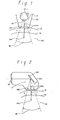
- Fig. 1 and Fig. 2 schematically illustrate previous probes which radiate (emit)/receive and scan sound waves using only one transducer element.
- 101 is a transducer which consists of one transducer element (hereinafter referred to as "element 101") and which generates a single sound-beam 1001.
- 101-1 is a transducer mount or base on which three or four elements, for instance, are mounted. Mount 101-1 is rotated to effect scanning over an angular range Wl as indicated by broken lines in Fig.l.
- 201 is a part of a transducer housing called a probe unit.
- 30 is a target such as a human body.
- 401 is a window made of acoustically transparent material which has almost the same acoustic impedance as the target 30 and is provided in an outer surface of probe unit 201. Window 401 seals in an acoustic transmission medium M , as described below, and contacts the target 30 to reduce ultrasonic loss between the probe unit 201 and the target 30.
- the acoustic transmission medium M is , for example, silicon rubber, water, or castor oil, filling the space between element 101 and window 401.
- Medium M has almost the same acoustic impedance as the window 401, to reduce ultrasonic loss between element 101 and window 401.
- 102 is a transducer which consists of one transducer element and generates a single sound-beam 1002.
- 202 is a probe unit
- 402 is a window
- 502 is an acoustic reflector placed in a sound path between element 102 and window 402.
- Reflector 502 oscillates for scanning single-beam 1002 over an angular scanning range W2 as indicated by broken lines in Fig. 2.
- a sound path between element 102 and window 402 is filled by an acoustic transmission medium M, as described in respect of Fig. 1.
- Received electronic signals are usually displayed on a cathode-ray tube in synchronism with scanning, to provide visible information (an ultrasonic tomogram) on the basis of sound echoes.
- the array transducer utilizes advanced technology for fabrication and control of a multi-element transducer.
- the array transducer generates, focuses, and scans a synthesized sound beam (SS-beam).
- the array transducer is a combination of small transducer elements. Wave-fronts of single-beams from each small transducer element are combined together to form an SS-beam. This SS-beam can be focused or scanned by controlling the phase or sequence of the electric pulse signals applied to the elements of the array.
- Synthesis of a sound beam or phase control of sequential pulse signals applied to each element of an array transducer can be effected by an electric delay-line or a sequential switch control circuit. Signals received by each transducer element are processed to produce signals for providing a display, using the same delay-line or the same sequential switch control circuit.
- array transducer There are two kinds of array transducer, one is a phased array transducer and the other is a linear array transducer.
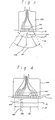
- Fig. 3 shows schematically a probe unit having a phased array transducer.
- 203 is a probe unit
- 103 is a phased array transducer which is composed of a plurality of transducer elements 1031.
- the elements 1031 are arranged in a plane and installed on an outer face of probe 203.
- All of elements 1031 are activated at the same time but the phases of the electric pulse signals applied to the individual elements 1031 are controlled to generate and scan an SS-beam 1003 over an angular scanning width W3 as indicated by broken lines in Fig.3.
- a linear array transducer generates an SS-beam by using a sub-group of the elements of the array transducer, consisting of four or five elements, for instance.
- This SS-beam is shifted in parallel (transversely across the transducer) by shifting elements making up the sub-group one by one along the array line of the transducer, by sequentially switching pulse signals applied to the sub-group elements.
- Fig. 4 shows schematically a typical probe unit having a linear array transducer.
- 204 is a probe unit
- 1034 is a linear array transducer, which is arranged in a plane and installed on an outer face of probe 204, having a plurality of elements 1041.
- Sequential switching of pulse signals applied to the individual elements of sub-group 1042 is controlled by a sequential switch control circuit to generate SS-beam 1004 and make it shift in parallel (transversely of the beam direction) as shown by arrow W4 over a range indicated by broken lines.
- Fig.5 and 6 show special probe units having array transducers using linear array techniques.
- Fig. 5 illustrates schematically a probe unit 205 using a concave linear array transducer 105 which has sub-group of elements 1052.
- Sub-group 1052 generates an SS-beam 1005 which is scanned over a scanning angular width W5 as indicated by broken lines.
- Transducer 105 is located within the probe 205, so that scanning of a target 30 over scan width W5 can be effected, and thus a window 405 and a medium M are required.
- This concave linear array system is able to sector scan a sound beam as with a phase array system with a high angular resolution. More detail is disclosed in Japanese Patent Publication No. jitsukosho 52-41267.
- Fig. 6 illustrates schematically a probe unit 206 using a convex linear array transducer 106 which has a sub-group of elements 1062.
- Sub-group 1062 generates SS-beam 1006 and scans over an angular scanning width W6 as indicated by broken lines.
- An acoustic transmission medium M is provided between the transducer and a window in the probes of Figs. 1,2,and 5.
- This medium is intended to reduce ultrasonic power losses.
- it is difficult to make the acoustic impedances of the medium and the window exactly equal, and consequently a part of a radiated sound wave is reflected back at the surface of the window towards the transducer and a part of the reflected sound wave is reflected again by the surface of the transducer towards the window.
- acoustic multi-reflection occurs in the acoustic path between the transducer and the window.
- Acoustic multi-reflection occurs not only in relation to a window but also in relation to a target because, as shown in Figs. 1 to 6, there are acoustic boundaries within a human body, such as the surface of the skin 31, and boundary 32 between different tissues near the skin 31.
- arrowed lines 2001,---,2006 indicate sound waves reflected from windows and target boundaries, and it will be evident that multi-reflection will occur in a center part of the scanning angular width in the case of Figs. 1,2,3 and 5, and over the whole scanning angular width in the case of Figs. 4 and 6.
- Fig.7 shows patterns of received signals.
- the horizontal axis corresponds to time T
- the vertical axis corresponds to signal amplitude A.
- Fig.7(a) illustrates ideal received signals, without any multi-reflection effects.
- 71 is a transmitting pulse
- 72 is an echo signal from a window
- 73 is an echo signal from the region of the surface of a human body (skin 31 and boundary 32)
- 74 are echo signals from within a human body, from which medical diagnostic information is to be taken.
- F ig. 7(b) shows a model of echo signals from the window 72, and consequent multi-reflected signals 72-1, 72-2, and 72-3.
- Fig. 7(c) shows a model of echo signals from the region of the surface of a human body 73, and consequent multi-reflected signals 73-1,73-2, and 73-3.
- Fig.7(d) shows a combination of signals as shown in Figs. 7(a), 7(b), and 7(c), which actually appears on a display.
- the present invention can provide an electro-sound transducer protected from the effects of acoustic multi-reflection which can give rise to erroneous medical information in ultrasonic diagnostic apparatus.
- Embodiments of the present invention reduce acoustic multi-reflection by reducing the reflection on the surface of the electro-sound transducer, by
- An embodiment of the present invention can provide for a reduction in acoustic multi-reflection between a transducer and a window of an ultrasonic diagnostic apparatus or a target such as a human body.
- the present invention provides for the avoidance of reflection at a surface of a transducer element. If a reflected sound wave is avoided or eliminated at the surface of the transducer element multi-reflection will not occur.
- Some embodiments of the present invention avoid multi-reflection by a rearrangement of array transducer elements so that the main direction of an SS-beam generated by the array transducer is different from the direction of a line normal to each element surface.
- acoustic matching layer(s) to a piezo-electric device. Multi-reflection is avoided by setting thickness and impedance of such acoustic matching layer(s) so that the phases of sound waves reflected from the surfaces of the piezo-electric device and the acoustic matching layer(s) respectively are opposite, so that the reflected waves cancel.
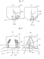
- Figs.8,9,11,12, and 14 can be seen to be similar to the apparatus of Fig.2 in that they each employ a scanning reflector in probe unit. These embodiments are, however, each provided with an array transducer, which generates SS-beam, rather than a one-element transducer as shown in Fig.2. In these cases the array transducer does not function for scanning.
- FIGs. 13 and 15 can be seen to be similar to apparatuses of Figs. 3 to 6 in that they are each provided with an array transducer which not only produces an SS-beam but also effects scanning.
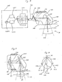
- Fig. 8 illustrates schematically ultrasonic diagnostic apparatus embodying the present invention.
- 208 is a probe unit including a phased array transducer 108, an acoustic reflector 508, a window 408, and an acoustic absorber 708.
- 308 is display equipment having driving unit 3081,phase control unit 3082, receive amplifier 3083, and display unit 3084.
- 608 is a cable connecting the display equipment 308 to probe 208.
- Driving unit 3081 generates pulse signals which have a specific repetition rate such as 200 KHz.
- a pulse is supplied through a phase control unit 3082 to cause the element to radiate or emit a sound wave.
- the phase control unit 3082 contains a plurality of delay-lines, each delay line provides a delayed pulse for each transducer element so that transducer 108 generates an SS-beam 1008 whose main direction is slanted with respect to a normal to the surface of transducer 108.
- transducer 108 The elements of transducer 108 are arranged in a plane F8 so that the surface of each element is arranged in parallel to the plane F8, which does not meet the main direction of the SS-beam 1008 at right angles.
- Reflector 508 is placed in the path of the SS-beam 1008 to reflect the SS-beam 1008 towards target 30 and is oscillated to provide scanning.
- W8 indicates scanning angular width.
- Received signals (pulses) which come from each of the transducer elements of transducer 108 pass through respective delay-lines , and are added together, and fed to receive aplifier 3083.
- An output of the receive amplifier 3083 is fed to display unit 3084 where diagnostic information based on the received signals can be displayed.
- Arrowed chain lines 2008 in Fig.8 illustrate sound waves reflected by window 408 and target 30. These reflected waves travel back towards transducer 108, and are reflected again by the surface of transducer 108. However, as shown in the Figure, they are then absorbed by absorber 708. Thus, multi-reflection can be avoided in the apparatus of Fig.8.
- Fig.9 shows another probe unit embodying the present invention.
- the transducer is a phased array transducer but a delay-line is not utilised.
- 209 is a probe unit
- 109 is a phased array transducer which radiates an SS-beam 1009
- 709 is acoustic absorber
- 509 is an acoustic reflector which is oscillated to provide scanning of the SS-beam 1009
- 409 is a window
- F9 is a plane on which each element of transducer 109 is arranged
- 30 is a target.
- the direction of a normal to plane F9 is the same as the main direction of SS-beam 1009 and each element of transducer 109 is installed in plane F9, but the directions of normals to individual transducer element surfaces are different from the main direction of SS-beam 1009.
- the individual elements are arranged to generate SS-beam 1009 by applying electric pulse signals to each element without using a delay-line.
- each element surface is selected in a regular fashion by slightly increasing the angle of each element with respect to neighboring elements .
- each element surface may take a direction randomly selected within a considerable range, which is determined as follows.
- Fig. 10 illustrates the directivity of a sound-beam formed by a transducer element, giving a view of a cut or slice of the sound-beam pattern.
- 100 is a transducer element (element 100)
- 1100 is the directional pattern of an element sound-beam
- transducer 109 of Fig.9 it is desirable than an angle ( ⁇ ), between a direction of a normal to an element surface and a main direction of the SS-beam, is less than ⁇ . Furthermore, it is desirable that the angle ß of each element is equal on average, to have a uniform SS-beam while scanning.
- Fig.11 shows another embodiment of the present invention with a probe unit which uses a phased array transducer technique without using a delay line.
- 211 is a probe unit
- 111 is a phased array transducer
- 1011 is the main direction of an SS-beam
- 711 is an acoustic absorber
- 511 is an acoustic reflector
- 411 is a window
- Fll is a plane in which each element of transducer 111 is arranged
- 30 is a target.
- the direction of a normal to plane Fll is the same as the direction of SS-beam 1011.
- each element of transducer 111 is installed in plane Fll so that the direction of a normal to the element surface is different from the direction of SS-beam 1011 (and from a normal to plane Fll).
- the directions of the normals to the element surfaces are all equal corresponding to an angle to the SS-beam which should be less than ⁇ as described in Fig.10.
- angular difference between element surfaces and plane Fll is selected so as to generate SS-beam 1011 directed along a normal to Fll, by using electric pulse signals all of the same phase (without using a delay line).
- Fig. 12 shows another embodiment of the present invention having a probe unit which uses a phased array transducer without employing a delay line.
- 212 is a probe unit
- 112 is a phased array transducer which is separated to several transducer element units, called sub-units 1123.
- 1012 is the main direction of an SS-beam
- 712 is acoustic absorber
- 512 is an'acoustic reflector
- 412 is a window
- F12 is a plane on which each sub-unit 1123 is arranged
- 30 is a target.
- Transducer 112 is separated to several sub-units 1123.
- Each sub-unit 1123 is composed of less than ten transducer elements. By using such sub-units 1123, it is possible to cut production costs relative to the costs of array transducers such as are shown in Fig.9 and 11 and to save element assembly time.
- Each sub-unit 1123 has its own plane in which its transducer elements are installed, and generates a sub-unit SS-beam 1012. The direction of a normal to the plane of a sub-unit 1123 is not the same as the main direction of SS-beam 1012.
- Sub-units 1123 are supplied with electric pulse signals all of the same phase without using a delay-line and generate SS-beam 1012. Scanning is performed by oscillating the reflector 512.
- Chain lines 2012 show waves reflected from window 412 and target 30 which, it will be seen, are reflected by the surfaces of sub-units 1123 and absorbed by absorber 712.
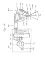
- Fig.13 shows a schematic diagram of ultrasonic diagnostic apparatus embodying the present invention which has a concave array transducer controlled by a combination of a linear-array and a phased-array transducer technique.
- 213 is a probe unit including a linear array transducer 113, a window 413, and an acoustic absorber 713.
- 313 is a display equipment having a driving unit 3131, a phase control unit (P-unit) 3132, a receive amplifier 3133, a sequential switch control unit (S-unit) 3134, and a display unit 3135.
- 613 is a junction cable.
- Transducer 113 is basically a concave linear array type transducer and sub-group elements 1132 are activated to generate and scan SS-beam 1013.
- a delay-line in P-unit 3132 controls the phase of electric pulse signals to each element of sub-group 1132, while multiplexer S-unit 3134 switches the connection of delay-lines to sub-group 1132, shifting the sub-group element by element to provide a linear array scanning.
- transducer 113 generates SS-beam 1013 and scans over an angular width W13 and reflected waves 2013 from window 413 or target 30 are absorbed by absorber 713 as shown in Fig.l3.
- Effective distance between transducer 113 and target 30 varies as the excited part of transducer 113 shifts along the array to scan the SS-beam 1013. Therefore, the variation in this distance should be compensated for in receiving unit 3133.
- variable aperture is a technique for obtaining high angular resolution at either a near or a far distance
- dynamic focusing is a technique with which high range resolution can be obtained. More details of “variable aperture” and “dynamic focusing” are disclosed, for example, in “Expanding-aperture Annular Array” by D.R.Dietz, S.I. Parks, and M. Linzer ; Center for Materials Science National Bureau of Standards Washington, D.C.20234.
- a direction of the transducer array is included in an SS-beam scanning plane of SS-beam.
- Fig.l4(A) is a sectional elevation view and Fig.l4(B) is a sectional plan view illustrating such a slant arrangement.
- 214 is a probe unit
- 114 is a phased array transducer
- 514 is a reflector which is oscillated to provide scanning
- 714 is an absorber
- 414 is a window
- 30 is a target.
- SS-beam 1014 is generated aslant by transducer 114 and is scanned by reflector 514 over an angular width W14. Reflected wave 2014 from window 414 or target 30 is reflected again by the surfaces of the elements of transducer 114, but is then absorbed by absorber 714. As a result, multi-reflection can be avoided.
- Fig. 15(A) and (B) show schematically embodiments of the present invention having probe units each using a phased array transducer which is installed aslant with respect to the surface of a window and a target to avoid multi-reflection.
- 215A is a probe unit
- l15A is a phased array transducer
- 415A is a window
- M is a space filling (acoustic transmission) medium
- 30 is a target.
- 1015A is the main SS-beam direction
- 2015A shows the direction of-reflected waves reflected from window 415A and target 30.
- the direction of the array is not parallel to the surfaces of window 415A and target 30, to avoid multi-reflection.
- transducer 115A When transducer 115A generates SS-beam 1015A and scans target 30 through window 415A reflected waves 2015A from the surfaces of window 415A and target 30 are reflected by the surface of transducer 115A, and the reflected waves will be reflected again by the surfaces of window 415A or target 30.
- this second reflected wave 20151A arrives at the surface of transducer element 1151A so aslant that element 1151A does'not transduce the second reflected wave 20151A into electric signal, because the sensitivity of transducer 115A decreases for such a slant angle.
- reflected waves do not cause multi-reflection contamination of received signals as in Fig.7(d).
- Fig.l5(B) is similar to Fig.15(A) except that a convex transducer is used.
- a probe unit 215B has a phased array transducer 115B and the elements of transducer 115B are arranged in a convex surface.
- This transducer 115B is installed in probe 215B so that the axis of the convex face is slanted with respect to the surface of window 415B and target 30.
- Acoustic transmission medium M fills the space between transducer 115B and window 415B.
- Fig.16 shows another embodiment of the present invention having a probe unit 216 which has a phased array transducer 116, arranged on a wall surface of probe 216.
- the direction of a normal to the surface of each element of transducer 116 is different from the direction of SS-beam 1016 generated by a phased array technique, so that a reflected wave 2016 does not cause multi-reflection.
- the directions of the element surfaces of transducer 116 can be set irregularly, though they look to be regularly arranged in Fig.16.
- the direction of each transducer element is required to avoid multi-reflection and is such that 1> is less than ⁇ with uniform distribution as mentioned in relation to Figs. 9 and 10.
- Fig.17 shows further embodiments of the present invention using probe units 217A and 217B respectively having convex array transducers 117A and 117B, to which a linear array transducer technique is applied. It can be said that probes 217A and 217B are modified forms of probe 106 of Fig.6 such as to avoid multi-reflection.
- Fig.17(A) only half of the array elements of transducer 117A are shown for simplicity.
- 1171A is an element of the transducer
- P is the center point of the convex face on which the elements of 117A are arranged
- 5017 is a normal to the surface of the convex face
- 4017A is a normal to the surface of element 1171A.
- Fig.17(B) is similar to Fig.17(A), but the elements of transducer 117 B are grouped and separated into sub-units 1173. A sub-unit SS-beam is scanned by a linear array transducer technique.
- transducer 117B In Fig.17(B), only half of transducer 117B is shown for the sake of simplicity.
- P is the center point of a convex face on which sub-units 1173 are arranged
- 5017B is a normal to the convex face
- 4017B is a normal line to the surface of a sub-unit 1173.
- Each sub-unit 1173 is installed in the convex face, and the normal to the surface of each sub-unit 1173 is settled so that it makes an angle ß to 5017B to satisfy the requirement mentioned in relation to Fig.10.
- Fig.18 shows schematically diagram of an embodiment of the present invention having a probe unit 218 having an array transducer which has a two-dimensional structure.
- Fig.l8(A) and Fig.l8(B) are respective sectiional views taken in mutually perpendicular planes.
- 218 is a probe unit
- 118 is a transducer
- 1184 is a phased element array (P-element)
- 418 is a window
- M is an acoustic transmission medium
- 30 is a target
- 1018 is the main direction of the SS-beam of P-elements 1184
- 2018 is a wave reflected from the surface of window 418 or target
- ß is the angle between the direction of normals to the surfaces of P-elements 1184 and the SS-beam 1018
- W18 is scanning angular width as indicated by broken lines.
- SS-beam 1018 is generated by P-elements 1184 using a phased array technique.
- a scan is achieved applying a linear array technique to each P-elements in turn.
- Angle A should be selected so that multi-reflection can be avoided, as described with reference to Fig.l5(A), and it is desirable thatJ5 be less than ⁇ as described with reference to Fig.10.
- the acoustic phase technique of the present invention has two varieties, an acoustic matching layer technique, and an acoustic matching surface technique.
- Figures 19 to 27 relate to the former, whilst Figures 28 to 32 relate to the latter.
- Fig.19 illustrates the structure of an electro-sound transducer
- Fig.20 is a diagram for assistance in explaining basic concepts of acoustic phase in acoustic medium.
- a transducer element 800 consists of a piezo-electric device 801, an acoustic matching layer 802, and an acoustic damper 803.
- device 801 has a front face and a back face. Sound waves are radiated from and received at the front face.
- Layer 802 is attached to the front face of device 801, and a front face of layer 802 is directly contacted to a target 30.
- Damper 803 is attached to the back face of device 801 to absorb backward radiated sound waves.
- Thickness of layer 802 is nearly (approximately) a quarter of the wavelength of sound waves emitted by 801.
- Layer 802 is usually provided for impedance matching so that sound waves are effectively radiated into target 30 in a short pulse period. More detail is disclosed in Japanese Patent Publication No. tokukosho 55-33020.
- layer 802 is modified so that the acoustic impedances looking into the layer from its two main surfaces are equal to the impedances of the media attached to those respective surfaces, and internal impedance of the layer is varied linearly from one end to the other. This is explained in more detail in Japanese Patent Publication No. tokukuoshoo 58-18095.
- Embodiments of the present invention avoid front and/or back multi-reflection, by using one or more acoustic matching layers to achieve phase cancellation.
- Fig.20 illustrates some fundamental principles of acoustic reflection.
- 8202, 8203, and 8204 are acoustic media having acoustic impedances Z l, Z2, and Z3 respectively.
- media 8202 and 8204 have sufficient thickness and uniformity for it to be considered that they give rise to no reflections, but that medium 8203 has a thickness of a quarter of a sound wavelength.
- input acoustic impedance Zin at boundary face 8201 between 8203 and 8204 can be expressed as:
- the phase of a wave reflected at a boundary surface 8201 is opposite to that of a wave reflected by the boundary surface between 8203 and 8202, so that the reflected waves from the two boundary faces cancel out.
- Fig.21 illustrates a general structure for transducer elements embodying the present invention having acoustic layers on both faces of a piezo-electric device.
- 805 is a transducer element
- 30 is a target
- 801 is a piezo-electric device
- 802 indicates front acoustic matching layers (F-layer) including a layer 8021 contacting target
- 803 is an acoustic damper
- 804 indicates back acoustic matching layers (B-layer).
- F-layer 802 has layers N . in number each of a thickness equal to a quarter of a sound wavelength and having acoustic impedance Ztl, Zt2,---, and Ztn.
- B-layer 804 has layers M in number and each of a thickness equal to a quarter of a sound wavelength and having acoustic impedances Zbl, Zb2 to Zbm.
- Zb is the acoustic impednace of damper 803
- Zt is the acoustic impedance of target 30.
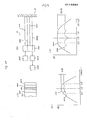
- FIG.22 is for explanation of an embodiment of this invention using such a transducer.
- (A) is a cross sectional view of the transducer illustrating the structure of its elements
- (B) illustrates a measuring system used to test multi-reflection of the transducer element
- (C) is a graph illustrating measured results showing characteristics of a previous transducer element
- (D) is a graph illustrating measured results showing characteristics of a transducer element according to this embodiment of the present invention.
- 8011 is a piezo-electric device
- 8022 and 8023 are front acoustic matching layers (F-layer) and F-layer 8022 contacts a target
- 8041 is a back acoustic matching layer (B-layer)
- 8031 is an acoustic damper.
- 800 is a transducer element in respect of which measurements are to be taken
- 35 is a completely reflecting target for sound waves
- 34 is acoustic medium consisting of pure water filling the space between element 800 and reflector 35
- 8225 is a driver which drives element 800 to radiate sound waves
- 8226 is a receiver which receives and amplifies the electric output signal from element 800
- 8227 is a spectral analyzer (spe-ana) which spectrally analyzes the electric signals received by receiver 8226.
- Driver 8225 drives element 800, by an electric pulse signal , to radiate a sound wave 1022. Radiated sound wave 1022 is reflected by target 35, so that reflected sound wave 1022, which is called a primary reflected wave, returns to element 800 producing a receiving signal. However, a part of reflected sound wave 1022 is reflected again by the surface of element 800 sending a sound wave 2022 towards target 35. Sound wave 2022 is again reflected by target 35, so that reflected sound wave 2022, which is called a secondary reflected wave, returns to element 800, producing again a receiving signal. This will occur repeatedly to cause multi-reflection.
- the graph of Fig.22(C) illustrates spectral intensity of reflected waves.
- Curve 8221 shows the intensity of the primary reflected wave and the broken-lined curve 8222 shows the spectral intensity of the second reflected wave, measure for a previous transducer element such as is shown in Fig.19.
- the graph shows that the prior element has only 6 dB difference between the primary and secondary reflected waves in the 3.5 M Hz sound frequency region.
- the graph of Fig.22(D) illustrates spectral intensity of reflected waves for an element as shown in Fig.22(A).
- the impedances relating to this element at 3.5 M Hz are as follows:
- Fig.22(D) shows that the difference between primary and secondary reflected waves is as much as 26 dB. Therefore, it can be said that the transducer element shown in Fig.22(A) reduces multi-reflection by more than 20 dB compared to the previous transducer.
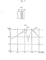
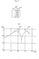
- Figs. 23 to 26 give graphs showing results of measurement, carried out with the measuring system of Fig.22(B), for comparison of intensities of primary and secondary reflected waves with other transducers embodying the present invention which are also illustrated in the respective Figures. Measurement was carried on for a frequency regiion of 3.5 M Hz. Impedance of the piezo-electric device in each case was as for 8011 in Fig.22(A) , but the impedances of other sections of the transducers, shown in Figures 23 to 26, were as follows:
- the various acoustic impedances were achieved by selecting the materials forming the layers from the following :
- this synthetic resin is useful for the acoustic matching layer, because it is also an adhesive material, so that the layer can be attached to the piezo-electric device without the need for the use of another adhesive material which might degrade transducer performance.
- a criterion by which the importance of the results of the multi-reflection tests for transducers embodying the present invention can be judged can be seen from the following.
- Fig.27 is a graph of reflection level versus depth showing experimental results obtained by a previous transducer element which indicates relative levels of sound echoes and multi-reflections in a case in which the human heart is the target.
- sound echo levels and reflected sound levels are on the ordinate and depth from skin surface shown on the abscissa.
- tl is the level of sound echoes from the 20 mm deep tissue
- t2 is the level of sound echoes from the heart wall
- tl is the level of reflected sound arising from multi-reflection at the 20 mm deep tissue. This Figure illustrates the disturbance caused by tl for detection of t2.
- reflection factor ( R ) of the transducer should be less than -lOdB in accordance with following equation (5);
- Reflection factor of a previous transducer as described above is from -6 dB to -10 dB, and from experience up to now this has resulted in only poor acoustic tomograms being obtained, as a result of multi-reflection.
- transducers in accordance with the present invention have reflection factors less than -15dB at 3.5 M Hz. Thus, such transducers are very effective for avoiding problems of multi-reflection.
- Figs. 22(A) to 26 use an acoustic matching layer technique.
- Other embodiments of the present invention avoid multi-reflection problems by using an acoustic matching surface technique.
- Fig.28 illustrates phase relationship between incident and reflected sound waves at the boundary faces of acoustic media.
- 901, 902, and 930 are acoustic media which have acoustic impedances Z10, Z20, and Z30 respectively.
- 9281 is an incident sound wave arriving at the faces of medium 901 and medium 902 through medium 930.
- 9282 is a sound wave reflected by the face of medium 901, and 9283 is a sound wave reflected by the face of medium 902.
- the reflection factor R13 looking from medium 930 towards medium 901 is
- the reflection factor R23 looking from medium 930 towards medium 902 is
- Fig.29 illustrates an embodiment of the present invention utilizing the acoustic matching surfce technique.
- A is a front view of a transducer
- B is a sectional view of the transducer 9291 along line 9290 in (A).
- 9011 is a piezo-electric device
- 9021 is an acoustic medium
- 9031 is an acoustic damper
- 9051 is coating material
- Ll is the thickness of device 9011 along the direction of incident sound waves.
- device 9011 has a number of holes distributed uniformly over the face of device 9011, and medium 9021 fills these holes.
- Coating 9051 coats the front face of device 9011, the front face of coating 9051 contacts a target to be diagnosed, and damper 9031 is attached to the back face of device 9011.
- Fig. 30 shows a sectional side view of a transducer 9301 which is a modifiction of transducer 9291 of Fig.29 such that reflected waves at the back face of the piezo-electric device can also be cancelled.
- 9301 is a transducer element
- 9012 is a piezo-electric device having a number of holes distributed uniformly over its face
- 9022 is an acoustic medium which fills these holes
- 9052 is a coating material
- 9032 is an acoustic damper for device 9012
- 9033 is an acoustic damper for medium 9022
- L2 and L3 are the thicknesses of device 9012 and medium 9022 respectively along the direction of incident sound waves.
- Wavelengths in the above media are different, because sound velocity depends on the acoustic characters of the media.
- wavelength in device 9012 is longer than wavelength in medium 9022, therefore L2 is longer than L3.
- the "device” and “medium” are each made of a single material respectively.
- cases in which each individual device and medium are made of different kinds of material can be considered.
- the present invention encompasses such cases.
- the equation (12) can be applied, except that the reflection factors must be extended or generalized as substantial combination reflection factors of the "device” and the “medium” respectively.
- Fig.31 illustrates a transducer element 9311 in accordance with another embodiment of the present invention.
- A shows a front view of element 9311
- B shows a sectional view taken along line 9310 in (A).
- 9013 is a piezo-electric device
- 9023 is acoustic medium which is glued on the front face of element 9311 being distributed uniformly in the fashion of the holes in Fig.29
- 9053 is an acoustic coating which coats the front face of device 9013 and medium 9023
- 9034 is an acoustic damper attached to the back face of device 9013
- t is thickness of medium 9023 along the direction of incident sound waves, which should be so small that it does not affect phase cancellation.
- Embodiments mentioned above relate to the avoidance of acoustic multi-reflection at the front and back faces of the piezo-electric device.
- similar means can be applied hot only to the piezo-electric device but also to the acoustic coating or the acoustic damper independently in accordance with the invention.
- Fig.32 illustrates another electro-sound transducer embodying the invention.
- 9321 is an array transducer consisting of a piezo-electric device 9014 and acoustic medium 9024. Forward multi-reflection can be avoided by providing impedance and area of device 9014 and medium 9024 so as to satisfy an equation similar to equation (10).
- transducer 9321 can be fabricated simply by filling the gaps with acoustic medium 9024.
Landscapes
- Physics & Mathematics (AREA)
- Engineering & Computer Science (AREA)
- Acoustics & Sound (AREA)
- Multimedia (AREA)
- Investigating Or Analyzing Materials By The Use Of Ultrasonic Waves (AREA)
- Transducers For Ultrasonic Waves (AREA)
- Ultra Sonic Daignosis Equipment (AREA)
Applications Claiming Priority (6)
| Application Number | Priority Date | Filing Date | Title |
|---|---|---|---|
| JP57234070A JPS59125549A (ja) | 1982-12-30 | 1982-12-30 | 超音波診断装置 |
| JP234070/82 | 1982-12-30 | ||
| JP58019182A JPS59145960A (ja) | 1983-02-08 | 1983-02-08 | 超音波探触子 |
| JP19182/83 | 1983-02-08 | ||
| JP39908/83 | 1983-03-10 | ||
| JP3990883A JPS59166139A (ja) | 1983-03-10 | 1983-03-10 | 超音波トランスデュ−サ |
Related Child Applications (1)
| Application Number | Title | Priority Date | Filing Date |
|---|---|---|---|
| EP89123763.8 Division-Into | 1989-12-22 |
Publications (3)
| Publication Number | Publication Date |
|---|---|
| EP0113594A2 true EP0113594A2 (de) | 1984-07-18 |
| EP0113594A3 EP0113594A3 (en) | 1985-09-18 |
| EP0113594B1 EP0113594B1 (de) | 1991-03-13 |
Family
ID=27282526
Family Applications (2)
| Application Number | Title | Priority Date | Filing Date |
|---|---|---|---|
| EP83308028A Expired EP0113594B1 (de) | 1982-12-30 | 1983-12-29 | Ultraschall-Diagnosegerät mit einem elektro-akustischen Wandler |
| EP89123763A Expired - Lifetime EP0366161B1 (de) | 1982-12-30 | 1983-12-29 | Elektroakustischer Wandler und eine Sonde oder ein diagnostisches Ultraschallgerät mit einem solchen Wandler |
Family Applications After (1)
| Application Number | Title | Priority Date | Filing Date |
|---|---|---|---|
| EP89123763A Expired - Lifetime EP0366161B1 (de) | 1982-12-30 | 1983-12-29 | Elektroakustischer Wandler und eine Sonde oder ein diagnostisches Ultraschallgerät mit einem solchen Wandler |
Country Status (3)
| Country | Link |
|---|---|
| US (1) | US4552021A (de) |
| EP (2) | EP0113594B1 (de) |
| DE (2) | DE3382720T2 (de) |
Cited By (2)
| Publication number | Priority date | Publication date | Assignee | Title |
|---|---|---|---|---|
| CN100441005C (zh) * | 2001-06-29 | 2008-12-03 | 富士施乐株式会社 | 无线通信设备 |
| CN110753841A (zh) * | 2017-06-20 | 2020-02-04 | 阿克森斯公司 | 用于声谱系统中的声发射器的保持装置 |
Families Citing this family (15)
| Publication number | Priority date | Publication date | Assignee | Title |
|---|---|---|---|---|
| DE8717504U1 (de) * | 1987-10-19 | 1989-01-05 | Siemens AG, 1000 Berlin und 8000 München | Stoßwellenquelle mit zentralem Ultraschall-Ortungssystem |
| US4862748A (en) * | 1988-07-20 | 1989-09-05 | The Boeing Company | Multiple ultrasonic transducer with remote selector |
| EP0634227B1 (de) * | 1993-07-15 | 1999-10-06 | General Electric Company | Breitband Ultraschallwandler und ihr Fabrikationsverfahren |
| JP3347654B2 (ja) * | 1997-10-29 | 2002-11-20 | キヤノン株式会社 | 駆動装置 |
| ATE513188T1 (de) * | 2003-04-28 | 2011-07-15 | Panasonic Corp | Ultraschallempfänger |
| DE102004043180B3 (de) * | 2004-09-01 | 2006-05-24 | Fraunhofer-Gesellschaft zur Förderung der angewandten Forschung e.V. | Vorrichtung zur zerstörungsfreien Prüfung von Bauteilen mittels Ultraschallwellen |
| KR100875208B1 (ko) * | 2005-12-09 | 2008-12-19 | 주식회사 메디슨 | 고강도 초점 초음파 시스템 |
| EP2051070A1 (de) * | 2007-10-18 | 2009-04-22 | Siemens Aktiengesellschaft | Verfahren und Vorrichtung zur zerstörungsfreien Materialprüfung eines Prüfgegenstandes mit Ultraschallwellen |
| KR101477544B1 (ko) * | 2012-01-02 | 2014-12-31 | 삼성전자주식회사 | 초음파 트랜스듀서, 초음파 프로브, 및 초음파 진단장치 |
| CN102590339A (zh) * | 2012-02-28 | 2012-07-18 | 上海斌瑞检测技术服务有限公司 | 一种无间隙多探头阵列扫描超声波探伤设备 |
| US9116098B2 (en) | 2013-02-12 | 2015-08-25 | General Electric Company | Ultrasonic detection method and system |
| US9482645B2 (en) | 2013-05-17 | 2016-11-01 | General Electric Company | Ultrasonic detection method and ultrasonic analysis method |
| WO2020113535A1 (zh) * | 2018-12-06 | 2020-06-11 | 深圳先进技术研究院 | 超声换能器 |
| CN115226011A (zh) * | 2021-04-15 | 2022-10-21 | 上海交通大学 | 基于电阻抗控制的声压调控器件 |
| CN113624849B (zh) * | 2021-08-11 | 2024-04-26 | 广州多浦乐电子科技股份有限公司 | 可优化固有波的延时块及超声探头 |
Family Cites Families (12)
| Publication number | Priority date | Publication date | Assignee | Title |
|---|---|---|---|---|
| GB766983A (en) * | 1951-07-17 | 1957-01-30 | Nat Res Dev | Improvements in devices for use in testing materials |
| FR1071199A (fr) * | 1952-11-07 | 1954-08-26 | Realisations Ultrasoniques Sa | Palpeur stratifié pour l'exploration et le traitement de matières par les ultrasons |
| GB1121523A (en) * | 1965-07-23 | 1968-07-31 | Le Vnii Elektromekhaniki | Electroacoustic transducer |
| US3821834A (en) * | 1972-07-18 | 1974-07-02 | Automation Ind Inc | Method of making an ultrasonic search unit |
| US3937068A (en) * | 1974-02-25 | 1976-02-10 | Joy Ivan L | Transducer arrangement for ultrasonic rail tester coupling carriages |
| US4153894A (en) * | 1977-08-09 | 1979-05-08 | The United States Of America As Represented By The Secretary Of The Department Of Health, Education And Welfare | Random phase diffuser for reflective imaging |
| GB2009563A (en) * | 1977-11-24 | 1979-06-13 | Emi Ltd | Ultrasonic probes |
| GB2011219A (en) * | 1977-12-21 | 1979-07-04 | Emi Ltd | Ultrasonic probes |
| US4197921A (en) * | 1978-04-06 | 1980-04-15 | Rca Corporation | Anti-reflective acoustic wavefront refraction element |
| US4195530A (en) * | 1978-08-14 | 1980-04-01 | Republic Steel Corporation | Ultrasonic inspection |
| JPS5920234B2 (ja) * | 1979-09-27 | 1984-05-11 | 沖電気工業株式会社 | 超音波送受波器 |
| US4300217A (en) * | 1980-07-30 | 1981-11-10 | Honeywell Inc. | Acoustic transducer housing |
-
1983
- 1983-12-29 DE DE89123763T patent/DE3382720T2/de not_active Expired - Fee Related
- 1983-12-29 EP EP83308028A patent/EP0113594B1/de not_active Expired
- 1983-12-29 EP EP89123763A patent/EP0366161B1/de not_active Expired - Lifetime
- 1983-12-29 DE DE8383308028T patent/DE3382209D1/de not_active Expired - Lifetime
- 1983-12-30 US US06/567,372 patent/US4552021A/en not_active Expired - Fee Related
Cited By (2)
| Publication number | Priority date | Publication date | Assignee | Title |
|---|---|---|---|---|
| CN100441005C (zh) * | 2001-06-29 | 2008-12-03 | 富士施乐株式会社 | 无线通信设备 |
| CN110753841A (zh) * | 2017-06-20 | 2020-02-04 | 阿克森斯公司 | 用于声谱系统中的声发射器的保持装置 |
Also Published As
| Publication number | Publication date |
|---|---|
| EP0366161A3 (en) | 1990-07-11 |
| DE3382720T2 (de) | 1994-03-31 |
| EP0113594A3 (en) | 1985-09-18 |
| EP0366161B1 (de) | 1993-11-03 |
| US4552021A (en) | 1985-11-12 |
| DE3382209D1 (de) | 1991-04-18 |
| DE3382720D1 (de) | 1993-12-09 |
| EP0113594B1 (de) | 1991-03-13 |
| EP0366161A2 (de) | 1990-05-02 |
Similar Documents
| Publication | Publication Date | Title |
|---|---|---|
| US4552021A (en) | Electro-sound transducer eliminating acoustic multi-reflection, and ultrasonic diagnostic apparatus applying it | |
| US4241611A (en) | Ultrasonic diagnostic transducer assembly and system | |
| US4211949A (en) | Wear plate for piezoelectric ultrasonic transducer arrays | |
| US5678554A (en) | Ultrasound transducer for multiple focusing and method for manufacture thereof | |
| US4217516A (en) | Probe for ultrasonic diagnostic apparatus | |
| US5991239A (en) | Confocal acoustic force generator | |
| US4387720A (en) | Transducer acoustic lens | |
| US5360007A (en) | Ultrasonic apparatus | |
| US4161121A (en) | Ultrasonic imaging system | |
| EP2237070B1 (de) | Doppelmodus-Ultraschallwandler | |
| US20100217124A1 (en) | Ultrasound imaging system and method using multiline acquisition with high frame rate | |
| US20020049381A1 (en) | Ultrasound system and ultrasound diagnostic apparatus for imaging scatterers in a medium | |
| GB2079456A (en) | Extended focus transducer system | |
| US5488953A (en) | Diffracting doppler-transducer | |
| US4204435A (en) | Devices using ultrasounds for forming images, in particular for _the internal examination of the human body | |
| US4441503A (en) | Collimation of ultrasonic linear array transducer | |
| US7291108B2 (en) | Ultrasonic transmission/reception apparatus for generating an image based on ultrasonic echoes and vibro-acoustic sounds | |
| US5081995A (en) | Ultrasonic nondiffracting transducer | |
| JPH03126443A (ja) | 超音波探触子 | |
| US6873569B2 (en) | Method, system and probe for obtaining images | |
| Ylitalo | On the signal-to-noise ratio of a synthetic aperture ultrasound imaging method | |
| US4794929A (en) | Echography probe and echograph fitted, with a probe of this type | |
| US4612809A (en) | Curved-array ultrasonic probe using low-velocity fluid | |
| US5486734A (en) | Acoustic transducer using phase shift interference | |
| JPH0226189B2 (de) |
Legal Events
| Date | Code | Title | Description |
|---|---|---|---|
| PUAI | Public reference made under article 153(3) epc to a published international application that has entered the european phase |
Free format text: ORIGINAL CODE: 0009012 |
|
| AK | Designated contracting states |
Designated state(s): DE FR GB NL SE |
|
| PUAL | Search report despatched |
Free format text: ORIGINAL CODE: 0009013 |
|
| AK | Designated contracting states |
Designated state(s): DE FR GB NL SE |
|
| RHK1 | Main classification (correction) |
Ipc: G10K 11/00 |
|
| 17P | Request for examination filed |
Effective date: 19851125 |
|
| 17Q | First examination report despatched |
Effective date: 19870810 |
|
| GRAA | (expected) grant |
Free format text: ORIGINAL CODE: 0009210 |
|
| AK | Designated contracting states |
Kind code of ref document: B1 Designated state(s): DE FR GB NL SE |
|
| XX | Miscellaneous (additional remarks) |
Free format text: TEILANMELDUNG 89123763.8 EINGEREICHT AM 29/12/83. |
|
| REF | Corresponds to: |
Ref document number: 3382209 Country of ref document: DE Date of ref document: 19910418 |
|
| ET | Fr: translation filed | ||
| PLBE | No opposition filed within time limit |
Free format text: ORIGINAL CODE: 0009261 |
|
| STAA | Information on the status of an ep patent application or granted ep patent |
Free format text: STATUS: NO OPPOSITION FILED WITHIN TIME LIMIT |
|
| 26N | No opposition filed | ||
| PGFP | Annual fee paid to national office [announced via postgrant information from national office to epo] |
Ref country code: FR Payment date: 19941209 Year of fee payment: 12 |
|
| PGFP | Annual fee paid to national office [announced via postgrant information from national office to epo] |
Ref country code: SE Payment date: 19941215 Year of fee payment: 12 |
|
| PGFP | Annual fee paid to national office [announced via postgrant information from national office to epo] |
Ref country code: GB Payment date: 19941220 Year of fee payment: 12 |
|
| PGFP | Annual fee paid to national office [announced via postgrant information from national office to epo] |
Ref country code: DE Payment date: 19941222 Year of fee payment: 12 |
|
| PGFP | Annual fee paid to national office [announced via postgrant information from national office to epo] |
Ref country code: NL Payment date: 19941231 Year of fee payment: 12 |
|
| EAL | Se: european patent in force in sweden |
Ref document number: 83308028.6 |
|
| PG25 | Lapsed in a contracting state [announced via postgrant information from national office to epo] |
Ref country code: GB Effective date: 19951229 |
|
| PG25 | Lapsed in a contracting state [announced via postgrant information from national office to epo] |
Ref country code: SE Effective date: 19951230 |
|
| PG25 | Lapsed in a contracting state [announced via postgrant information from national office to epo] |
Ref country code: NL Effective date: 19960701 |
|
| GBPC | Gb: european patent ceased through non-payment of renewal fee |
Effective date: 19951229 |
|
| PG25 | Lapsed in a contracting state [announced via postgrant information from national office to epo] |
Ref country code: FR Effective date: 19960830 |
|
| NLV4 | Nl: lapsed or anulled due to non-payment of the annual fee |
Effective date: 19960701 |
|
| PG25 | Lapsed in a contracting state [announced via postgrant information from national office to epo] |
Ref country code: DE Effective date: 19960903 |
|
| REG | Reference to a national code |
Ref country code: FR Ref legal event code: ST |