EP0113672A2 - Signalbearbeitungsmethode in der Autoradiographie - Google Patents
Signalbearbeitungsmethode in der Autoradiographie Download PDFInfo
- Publication number
- EP0113672A2 EP0113672A2 EP84100144A EP84100144A EP0113672A2 EP 0113672 A2 EP0113672 A2 EP 0113672A2 EP 84100144 A EP84100144 A EP 84100144A EP 84100144 A EP84100144 A EP 84100144A EP 0113672 A2 EP0113672 A2 EP 0113672A2
- Authority
- EP
- European Patent Office
- Prior art keywords
- cleavage products
- signal processing
- specific cleavage
- radioactively labeled
- phosphor sheet
- Prior art date
- Legal status (The legal status is an assumption and is not a legal conclusion. Google has not performed a legal analysis and makes no representation as to the accuracy of the status listed.)
- Withdrawn
Links
- 238000000376 autoradiography Methods 0.000 title claims abstract description 45
- 238000003672 processing method Methods 0.000 title claims abstract description 37
- OAICVXFJPJFONN-UHFFFAOYSA-N Phosphorus Chemical compound [P] OAICVXFJPJFONN-UHFFFAOYSA-N 0.000 claims abstract description 101
- 239000000126 substance Substances 0.000 claims abstract description 94
- 238000000034 method Methods 0.000 claims abstract description 73
- 238000012545 processing Methods 0.000 claims abstract description 65
- 238000005070 sampling Methods 0.000 claims abstract description 44
- 230000008569 process Effects 0.000 claims abstract description 29
- 238000003776 cleavage reaction Methods 0.000 claims description 94
- 230000007017 scission Effects 0.000 claims description 92
- 230000005855 radiation Effects 0.000 claims description 40
- UYTPUPDQBNUYGX-UHFFFAOYSA-N guanine Chemical compound O=C1NC(N)=NC2=C1N=CN2 UYTPUPDQBNUYGX-UHFFFAOYSA-N 0.000 claims description 28
- OPTASPLRGRRNAP-UHFFFAOYSA-N cytosine Chemical compound NC=1C=CNC(=O)N=1 OPTASPLRGRRNAP-UHFFFAOYSA-N 0.000 claims description 26
- RWQNBRDOKXIBIV-UHFFFAOYSA-N thymine Chemical compound CC1=CNC(=O)NC1=O RWQNBRDOKXIBIV-UHFFFAOYSA-N 0.000 claims description 22
- 229920001222 biopolymer Polymers 0.000 claims description 13
- 229940104302 cytosine Drugs 0.000 claims description 13
- 230000002285 radioactive effect Effects 0.000 claims description 12
- 239000012634 fragment Substances 0.000 claims description 11
- 229940113082 thymine Drugs 0.000 claims description 11
- GFFGJBXGBJISGV-UHFFFAOYSA-N Adenine Chemical compound NC1=NC=NC2=C1N=CN2 GFFGJBXGBJISGV-UHFFFAOYSA-N 0.000 claims description 10
- 229930024421 Adenine Natural products 0.000 claims description 10
- 229960000643 adenine Drugs 0.000 claims description 10
- 108020004707 nucleic acids Proteins 0.000 claims description 8
- 102000039446 nucleic acids Human genes 0.000 claims description 8
- 150000007523 nucleic acids Chemical class 0.000 claims description 8
- 108020004414 DNA Proteins 0.000 description 32
- 239000000463 material Substances 0.000 description 9
- 238000002601 radiography Methods 0.000 description 9
- 230000000007 visual effect Effects 0.000 description 7
- 238000004458 analytical method Methods 0.000 description 6
- 238000006243 chemical reaction Methods 0.000 description 5
- 239000000499 gel Substances 0.000 description 5
- 230000004936 stimulating effect Effects 0.000 description 5
- 238000012800 visualization Methods 0.000 description 5
- -1 DNA Chemical class 0.000 description 4
- 230000006870 function Effects 0.000 description 4
- 239000000203 mixture Substances 0.000 description 4
- 230000008901 benefit Effects 0.000 description 3
- 238000009826 distribution Methods 0.000 description 3
- 238000001962 electrophoresis Methods 0.000 description 3
- 108090000623 proteins and genes Proteins 0.000 description 3
- 102000004169 proteins and genes Human genes 0.000 description 3
- 239000000941 radioactive substance Substances 0.000 description 3
- 238000003860 storage Methods 0.000 description 3
- 102000053602 DNA Human genes 0.000 description 2
- 229910052693 Europium Inorganic materials 0.000 description 2
- 230000003321 amplification Effects 0.000 description 2
- 238000010586 diagram Methods 0.000 description 2
- 230000005284 excitation Effects 0.000 description 2
- 238000001502 gel electrophoresis Methods 0.000 description 2
- 229910052739 hydrogen Inorganic materials 0.000 description 2
- 239000001257 hydrogen Substances 0.000 description 2
- 238000002955 isolation Methods 0.000 description 2
- 238000003199 nucleic acid amplification method Methods 0.000 description 2
- 229920000139 polyethylene terephthalate Polymers 0.000 description 2
- 239000005020 polyethylene terephthalate Substances 0.000 description 2
- 230000001681 protective effect Effects 0.000 description 2
- 230000035945 sensitivity Effects 0.000 description 2
- GGCZERPQGJTIQP-UHFFFAOYSA-N sodium;9,10-dioxoanthracene-2-sulfonic acid Chemical compound [Na+].C1=CC=C2C(=O)C3=CC(S(=O)(=O)O)=CC=C3C(=O)C2=C1 GGCZERPQGJTIQP-UHFFFAOYSA-N 0.000 description 2
- 238000012935 Averaging Methods 0.000 description 1
- 229920001747 Cellulose diacetate Polymers 0.000 description 1
- 239000000020 Nitrocellulose Substances 0.000 description 1
- VYPSYNLAJGMNEJ-UHFFFAOYSA-N Silicium dioxide Chemical compound O=[Si]=O VYPSYNLAJGMNEJ-UHFFFAOYSA-N 0.000 description 1
- 230000002776 aggregation Effects 0.000 description 1
- 238000004220 aggregation Methods 0.000 description 1
- 229910052784 alkaline earth metal Inorganic materials 0.000 description 1
- 150000001342 alkaline earth metals Chemical class 0.000 description 1
- 239000011230 binding agent Substances 0.000 description 1
- 238000001514 detection method Methods 0.000 description 1
- OGPBJKLSAFTDLK-UHFFFAOYSA-N europium atom Chemical compound [Eu] OGPBJKLSAFTDLK-UHFFFAOYSA-N 0.000 description 1
- 230000002068 genetic effect Effects 0.000 description 1
- 230000006872 improvement Effects 0.000 description 1
- 238000002372 labelling Methods 0.000 description 1
- 230000005012 migration Effects 0.000 description 1
- 238000013508 migration Methods 0.000 description 1
- 229920001220 nitrocellulos Polymers 0.000 description 1
- 239000002245 particle Substances 0.000 description 1
- 229910052698 phosphorus Inorganic materials 0.000 description 1
- 239000011574 phosphorus Substances 0.000 description 1
- 229920000728 polyester Polymers 0.000 description 1
- 229920006254 polymer film Polymers 0.000 description 1
- 238000004080 punching Methods 0.000 description 1
- 230000009467 reduction Effects 0.000 description 1
- 239000013558 reference substance Substances 0.000 description 1
- 229920005989 resin Polymers 0.000 description 1
- 239000011347 resin Substances 0.000 description 1
- 230000004044 response Effects 0.000 description 1
- 239000000741 silica gel Substances 0.000 description 1
- 229910002027 silica gel Inorganic materials 0.000 description 1
- 230000000638 stimulation Effects 0.000 description 1
- 229920003002 synthetic resin Polymers 0.000 description 1
- 239000000057 synthetic resin Substances 0.000 description 1
- 238000004809 thin layer chromatography Methods 0.000 description 1
- 229920006352 transparent thermoplastic Polymers 0.000 description 1
Images


Classifications
-
- G—PHYSICS
- G01—MEASURING; TESTING
- G01T—MEASUREMENT OF NUCLEAR OR X-RADIATION
- G01T1/00—Measuring X-radiation, gamma radiation, corpuscular radiation, or cosmic radiation
- G01T1/16—Measuring radiation intensity
- G01T1/20—Measuring radiation intensity with scintillation detectors
- G01T1/2012—Measuring radiation intensity with scintillation detectors using stimulable phosphors, e.g. stimulable phosphor sheets
- G01T1/2014—Reading out of stimulable sheets, e.g. latent image
-
- G—PHYSICS
- G01—MEASURING; TESTING
- G01T—MEASUREMENT OF NUCLEAR OR X-RADIATION
- G01T1/00—Measuring X-radiation, gamma radiation, corpuscular radiation, or cosmic radiation
- G01T1/16—Measuring radiation intensity
- G01T1/20—Measuring radiation intensity with scintillation detectors
- G01T1/2012—Measuring radiation intensity with scintillation detectors using stimulable phosphors, e.g. stimulable phosphor sheets
-
- Y—GENERAL TAGGING OF NEW TECHNOLOGICAL DEVELOPMENTS; GENERAL TAGGING OF CROSS-SECTIONAL TECHNOLOGIES SPANNING OVER SEVERAL SECTIONS OF THE IPC; TECHNICAL SUBJECTS COVERED BY FORMER USPC CROSS-REFERENCE ART COLLECTIONS [XRACs] AND DIGESTS
- Y10—TECHNICAL SUBJECTS COVERED BY FORMER USPC
- Y10S—TECHNICAL SUBJECTS COVERED BY FORMER USPC CROSS-REFERENCE ART COLLECTIONS [XRACs] AND DIGESTS
- Y10S250/00—Radiant energy
- Y10S250/909—Methods and apparatus ancillary to stimulable phosphor systems
Definitions
- This invention relates to a signal processing method in autoradiography.
- Autoradiography has been known as a method for obtaining locational information on radioactively labeled substances distributed in at least one dimensional direction to form distributed rows on a support medium.
- the autoradiography comprises steps of; labeling organism-originating biopolymers such as proteins or nucleic acids with a radioactive element; resolving the radioactively labeled biopolymers, derivatives thereof, or cleavage products thereof on a gel support (support medium) through a resolving process such as gel electrophoresis; placing the gel support and a high-sensitivity type X-ray film together in layers for a certain period of time to expose said film, developing said film, obtaining the locational information of the radioactively labeled substances from the developed film, and then performing the identification of the polymeric substances, determination of molecular weight thereof and isolation thereof based on the obtained locational information.
- the autoradiography has a prominent advantage in that visual observation of the locational information in a cell scale or a molecular scale on radioactively labeled substances can be made by utilizing the radiography as mentioned above.
- the investigators have determined the distribution of radioactively labeled substances in a sample by observing a visualized autoradiograph with eyes to obtain the locational information on the specific substances labeled with a radioactive element.
- a certain locational information as obtained above has been further subjected to various analyses to isolate or identify radioactively labeled substances, or to determine the molecular weight or characteristics of specific substances.
- the above-mentioned autoradiography is used effectively to determine the base sequence of nucleic acids such as DNA, and the method is considered to be of a value for determination of structure of polymeric substances originating from organisms. The determination of structure of such substances likewise requires the visual determination.
- the autoradiography is a useful method for analysis of the structure and function of tissue of organisms and/or of organism-originating substances, but it has unfavorable feature that the conventional autoradiography requires visual analysis, thereby needing a great amount of time and labor.
- the locational information obtained by the analysis of the autoradiograph varies depending on the investigators in charge because of inherent unreliability of visual observation, and the accuracy of the information is limited to a certain extent.
- an autoradiographic image visualized on a radiographic film has reduced quality (in regard of sharpness, contrast, etc.) so that satisfactory information can not be obtained and the accuracy is low.
- a visualized autoradiograph can been scanned by means of a device such as a scanning densitometer.
- a scanning densitometer In order to improve the accuracy of the locational information, for instance, a visualized autoradiograph can been scanned by means of a device such as a scanning densitometer.
- a scanning densitometer In order to improve the accuracy of the locational information, for instance, a visualized autoradiograph can been scanned by means of a device such as a scanning densitometer.
- scanning process requires increased time and complicated procedures.
- a sample and radiographic film is required to be placed together in layers for a long period of time to expose the film to a radioactive substance contained in the sample so as to visualize the autoradiograph having the above-mentioned locational information on the radiographic film (for instance several days are required).
- the exposure ought to be carried out at a low temperature (0°C to -90°C) to avoid appearance of the chemical fog of the photosensitive silver salt in the radiographic film which is caused by various substances contained in the sample.
- the exposure ought to be done under specific conditions.
- the photosensitive silver salt in a radiographic film has a drawback that it is also sensitive to physical impetus, or is apt to be physically fogged, careful and skillful handling is required. This feature further brings about another complexity in the autoradiographic procedure.
- the radiographic film is also exposed to certain natural radioactive substances contained in the sample other than the radioactively labeled substances under analysis during the exposure for a long period of time. Accordingly, this exposure also lowers the quality of the obtained image, in addition to the above-mentioned chemical and physical fogs do.
- the present inventors have discovered that the information on one dimensional location of the radioactively labeled substances is obtained in the form of symbol and/or numeral by a signal processing method which utilizes a radiation image recording and reproducing method using a stimulable phosphor sheet in place of the conventional radiography using a radiographic Film employed in the conventional autoradiography.
- Said signal processing comprises steps of obtaining a digital signal corresponding to the autoradiograph having the locational information on the radioactively labeled substances in a sample and subsequently processing the iigital signal.
- the autoradiography utilizing the above- identified signal processing requires no visualization of the autoradiograph. However, the visualization of the autoradiograph can be attached to the above-mentioned signal processing.
- the present invention provides a signal processing method in autoradiography for obtaining information on one dimensional location of radioactively labeled substances distributed in at least one dimensional direction on a support medium, in the form of symbol, numeral or combination thereof, which comprises:
- the visible image can be further obtained by attaching to the above-described digital processing method an additional process for reproducing the visible image from an electric or digital signal corresponding to said autoradiograph obtained by detecting said stimulated emission photoelectrically.
- the radiation image recording and reproducing method which is utilized in the present invention in place of the conventional radiography is described, for instance, in U. S. Patent No. 4,239,968, and said method comprises steps of: causing a stimulable phosphor of a stimulable phosphor sheet to absorb radiation energy having passed through an object or having been radiated by an object; exciting the stimulable phosphor with an electromagnetic wave such as visible light or infrared rays (hereinafter referred to as "stimulating rays") to sequentially release the radiation energy stored in the stimulable phosphor as light emission; photoelectrically detecting the emitted light to give an electric signal; and then reproducing the electric signal in the form of a visible image on a recording material, or converting the electric signal to digital signal through A/D conversion.
- an electromagnetic wave such as visible light or infrared rays
- the stimulable phosphor sheet contains a stimulable phosphor such as a divalent europium activated alkaline earth metal fluorohalide phosphor.
- a stimulable phosphor such as a divalent europium activated alkaline earth metal fluorohalide phosphor.
- the stimulable phosphor absorbs a portion of the radiation energy and then emits light (stimulated emission) corresponding to the radiation energy stored therein upon excitation with an electromagnetic wave (stimulating rays) such as visible light or infrared rays, after the exposure.
- the locational information on radioactively labeled substances J ne-dimensionally distributed on a support medium can be directly obtained in the form of digital signal without visualization by applying the above-mentioned radiation image recording and reproducing method to the autoradiography.
- an autoradiograph having the locational information on the radioactively labeled substances can be also obtained as a visible image from the digital signal or the electric signal having been subjected to no A/D conversion.
- the above-mentioned radiation image recording and reproducing method has such a practical advantage that a radiation image can be recorded over a wide range of radiation exposure in comparison with the conventional radiography. More in detail, it is known in this method that the amount of stimulated emission given by the stimulable phosphor upon excitation with stimulating rays after storing radiation energy is proportional to the amount of the radiation exposure over a wide range thereof. For this reason, the digital signal accurately corresponding to an autoradiograph of an object can be directly obtained by the above-mentioned method.
- a digital signal which is hardly affected even if the level of radiation energy stored in the stimulable phosphor sheet deviates depending upon variation of the exposure conditions brought about by variation of the conditions of the object, fluctuation of the sensitivity of the stimulable phosphor sheet, and fluctuation of the sensitivity of a photosensor, can be obtained by setting the read-out gain at an appropriate value.
- the method can be performed with less amount of radiation from the sample than the conventional radiography, and accordingly the radioactively labeled substances in the sample which are harmful to investigators can be reduced.
- the digital signal having the locational information on the radioactively labeled substances which is obtained by the above-mentioned radiation recording and reproducing method using a stimulable phosphor sheet, is processed in an appropriate signal processing circuit having a function of signal processing to give automatically the locational information in the form of desired symbol and/or numeral.
- this method requires no visual observation.
- the locational information represented by symbol and/or numeral can be further subjected to a suitable calculation or combined with other related information to obtain a desired information such as information concerning the structure or function of substance without any manual operation.
- the analysis of the autoradiograph can be automated by applying thereto the present invention comprising subjecting the digital signal corresponding to the autoradiograph having the locational information on the radioactively labeled substances to the digital signal processing, so that the time and labor required in the conventional radiography is reduced. Further, the locational information is obtained with high accuracy by the present invention.
- the information on the relative amount of the radioactively labeled substances on respective positions is also obtainable from the intensity of stimulated emission released from the stimulable phosphor sheet, in addition to the information on one dimensional location thereof.
- the quantitative information such as concentration distribution of the radioactively labeled substances can be obtained without applying an additional means to the autoradiograph as in the conventional autoradiography.
- the term "locational information" of the radioactively labeled substances means to include a variety of information relating to the location of the radioactively labeled substances, or the aggregation thereof, being present in the sample, such as the location, the shape, the concentration, the distribution and combinations thereof.
- the autoradiograph having the locational information on the radioactively labeled substances can be obtained in the form of a visible image in addition to the locational information in the form of symbol and/or numeral.
- the locational information obtained in the form of the symbol and/or numeral through signal processing can be compared or checked with the visible image. Otherwise, the obtained image can be also compared with separately visualized autoradiograph.
- the conventional radiography has been heretofore employed, it is very useful to visualize the autoradiograph of the present invention for comparison and identification with the known visible autoradiograph obtained in the conventional autoradiography.
- the visualization of the autoradiograph in the invention makes it possible that the locational information is recorded and stored in a form of visible image, in addition to storage of the information in the form of symbol and/or numeral in a magnetic tape or the like.
- a suitable image processing can be performed on the digital signal to obtain a well readable visible image, because the visualization of an autoradiograph of a sample is done for the electric signal and/or digital signal corresponding thereto.
- this method provides an advantage that the exposure of a stimulable phosphor sheet to a sample can be carried out under remarkably milder exposing conditions (period of time, temperature, etc.) than that required in the conventional radiography. This also brings about the improvement in the accuracy of autoradiography and the simplification of operation thereof.
- Examples of the sample used in the present invention include a support medium on which radioactively labeled substances are resolved in one dimensional direction to form a resolved row.
- Examples of the radioactively labeled substances include biopolymers, derivatives thereof, or cleavage products thereof, being labeled with a radioactive element.
- the present invention is useful for isolation and identification thereof. Further, the present invention can be effectively used to analyze the whole or partial molecular structures of these biopolymers and the basic segmental constitutions thereof.
- Representative examples of the method for resolving (or developing) the radioactively labeled substances on a support medium include an electrophoresis using one of various resolving mediums such as a gel in the form of layer, column or the like, a molded polymer film such as a cellulose diacetate film, and a filter paper, and a thin layer chromatography using a support of material such as silica gel.
- various resolving mediums such as a gel in the form of layer, column or the like, a molded polymer film such as a cellulose diacetate film, and a filter paper, and a thin layer chromatography using a support of material such as silica gel.
- the method employable in the present invention is by no means restricted to these methods.
- Samples employable in the present invention are by no means restricted to the above-mentioned samples, and any other samples can be used, provided that the sample is a support medium containing the radioactively labeled substances distributed one-dimensionally thereon and the autoradiograph having the locational information thereof can be recorded on the stimulable phosphor sheet.
- the stimulable phosphor sheet used in the present invention has a basic structure comprising a support, a phosphor layer and a transparent protective film.
- the phosphor layer comprises a binder and a stimulable phosphor dispersed therein, and for instance, it is obtained by dispersing particulate divalent europium activated barium fluoride (BaFBr:Eu2 + ) phosphor particles in a mixture of nitrocellulose and linear polyester.
- the stimulable phosphor sheet is, for example, prepared by providing the above-mentioned phosphor layer onto the support such as a polyethylene terephthalate sheet and then providing a protective film such as a polyethylene terephthalate sheet on the phosphor layer.
- the exposing procedure that is, the procedure of storing the radiation energy released from the support medium containing the radioactively labeled substance in the stimulable phosphor sheet
- at least a portion of the released radiation energy is absorbed in the stimulable phosphor sheet by placing the support medium and stimulable phosphor sheet together in layers for a certain period of time.
- the exposure can be accomplished by keeping the phosphor sheet in a position adjacent to the support medium, for instance, at a room temperature or lower temperature for at least several seconds.
- Figure 1 schematically illustrates an embodiment of the read-out system comprising a preliminary read-out section 2 for preliminarily reading out the one dimensional information on the location of the radioactively labeled substances stored (or recorded) in the stimulable phosphor sheet 1 (from which the sample generally has been removed; the stimulable phosphor sheet is hereinafter referred to as "phosphor sheet"), and a final read-out section 3 for finally reading out the desired locational information on the radioactively labeled substance stored in the phosphor sheet 1.
- phosphor sheet the stimulable phosphor sheet
- the preliminary read-out operation is carried out in the following manner.
- Laser beam 5 generated by a laser source 4 first passes through a filter 6 to cut off a light beam in the wavelength region corresponding to the wavelength region of stimulated emission to be emitted from the phosphor sheet 1 in response to stimulation with the laser beam 5.
- the laser beam 5 is subsequently deflected by a beam deflecter 7 such as a galvanometer mirror, and reflected by a plane reflecting mirror 8.
- the deflected beam then impinges upon the phosphor sheet 1.
- the laser source 4 used herein is so selected as to avoid overlapping of the wavelength region of the laser beam 5 with the main wavelength region of the stimulated emission to be emitted from the phosphor sheet 1.
- the phosphor sheet 1 is transferred to the direction along the arrow 9 under the irradiation of the above-mentioned deflected laser beam. Therefore, the whole surface of the phosphor sheet 1 is subjected to the irradiation of the deflected laser beam.
- the power of the laser beam 5 employed in the preliminary read-out section is adjusted to be lower than the power of the laser beam to be employed in the final read-out section by controlling the output of the laser source 4, the beam diameter of the laser beam 5, the scanning speed of the laser beam 5, and the transferring speed of the phosphor sheet 1.
- the phosphor sheet 1 When irradiated with the above-mentioned laser beam, the phosphor sheet 1 gives the stimulated emission having the emission intensity proportional to the radiation energy stored (or recorded) therein.
- the emission then enters into a light guiding sheet 10 for the preliminary read-out.
- the light guiding sheet 10 has a linear edge face for receiving the emission, and the edge face is so positioned in the vicinity of the phosphor sheet as to correspond to the scanning line on the phosphor sheet 1.
- the exit of the light guiding sheet 10 is in the form of a ring and is connected to an light-receiving face of a light detector 11 such as a photomultiplier.
- the light guiding sheet 10 is made, for instance, by processing a sheet of a transparent thermoplastic resin such as a polyacrylic synthetic resin, and so. constituted that the emission introduced from the linear edge face is transmitted to the exit under repeated total reflection within the sheet 10.
- the stimulated emission from the phosphor sheet 1 is guided in the interior of the light guiding sheet 10 to the exit, and received by the light detector 11.
- the preferable shape and material of the light guiding sheet is disclosed in Japanese Patent Provisional Publications No. 55(1980)-87970 and No. 56(1981)-11397, etc.
- a filter which allows only the light of wavelength region of the stimulated emission to pass through and cuts off the light of the wavelength region of the stimulating rays (laser beam) so as to detect only the stimulated emission.
- the stimulated emission detected by the light detector 11 is.converted to an electric signal, amplified in an amplifier 12 and transmitted to the output.
- the stored information output from the amplifier 12 is supplied to a control circuit 13 of the final read-out section 3.
- the control circuit 13 provides an amplification degree setting value a and a scale factor setting value b, for obtaining signal at an appropriate level.
- an image processing condition setting value c is set so that a well readable image having uniform concentration and contrast can be given regardless of variation of the detected information.
- the phosphor sheet 1 having been subjected to the preliminary read-out in the above-described manner is then transferred to the final read-out section 3.
- the laser beam 15 generated by a laser source 14 for the final read-out passes through a filter 16 having the same function as that of the above-mentioned filter 6, and then the beam diameter is precisely adjusted in a beam expander 17. Subsequently, the laser beam is deflected by a beam deflector 18 such as a galvanometer mirror, and reflected by a plane reflection mirror 19. The deflected beam then impinges one-dimensionally upon the phosphor sheet 1. Between the beam deflector 18 and the plane reflection mirror 19 a f8 lens 20 is provided so that the beam speed is continuously kept constant when the deflected laser beam is scanned on the phosphor sheet 1.
- a beam deflector 18 such as a galvanometer mirror
- the phosphor sheet 1 is transferred in the direction along the arrow 21 under the irradiation with the above-mentioned deflected laser beam. Accordingly, the whole surface of the phosphor sheet is subjected to the irradiation in the same manner as in the preliminary read-out operation.
- the phosphor sheet 1 When irradiated with the above-mentioned laser beam, the phosphor sheet 1 gives the stimulated emission in proportion to the radiation energy stored therein in the same manner as in the preliminary read-out operation. The emission then enters into a light guiding sheet 22 for the final read-out.
- the light guiding sheet 22 for the final read-out is made of the same material and has the same constitution as the light guiding sheet 10 employed for the preliminary read-out.
- the stimulated emission received is guided in the interior of the light guiding sheet 22 up to the exit under repeated total reflection, and then received by a light detector 23.
- a filter which allows only the light of wavelength region of the stimulated emission to pass through and cuts off the light of the wavelength region of the stimulating rays (laser beam) so as to detect only the stimulated emission.
- the stimulated emission detected by the light detector 23 is converted to an electric signal, amplified to an electric signal adjusted to an appropriate level in an amplifier 24 according to the aforementioned amplification degree setting value a and transmitted to an A/D converter 25.
- the adjusted electric signal is then converted to a digital signal in the A/D converter 25 according to an appropriate scale factor defined by the scale factor setting value b.
- the read-out operation employable in the present invention is not limited to the above-described embodiment.
- the preliminary read-out operation may be omitted if the content of the radioactive substances in the sample and an adequate exposure time for the sample is previously known.
- the digital signal corresponding to the autoradiograph of the radioactively labeled substances is. subsequently input into a signal processing circuit 26 shown in Figure 1.
- the digital signal is processed to give locational information on the radioactively labeled substances in the form of symbol and/or numeral. More in detail, a scanning line for the signal processing is determined and then sampling points along the scanning line are detected in the circuit 26. If desired, the signal can be further processed to visualize the autoradiograph according to the image processing condition setting value c.
- the digital signal processing according to the present invention is described below, referring to an example of an autoradiograph of a resolved row obtained by resolving a mixture of radioactively labeled substances on a support medium through electrophoresis or the like:
- Figure 2 shows an example of the autoradiograph of a sample which comprises the support medium on which a plurality of radioactively labeled substances are resolved linearly in the longitudinal direction thereof.
- the digital signal obtained by applying the radiation image recording and reproducing method to the sample as described above, that is, the digital signal received by the signal processing circuit 26 shown in Fig. 1, is provided with an address (X, Y) which is represented by a coordinate system defined by the stimulable phosphor sheet and with a signal level (Z) in each address corresponding to the intensity of stimulated emission. Accordingly, the digital signal corresponds to the autoradiograph shown in Figure 2.
- the digital image data having the locational information on the above-mentioned radioactively labeled substances are given to the signal processing circuit 26.
- the term "digital image data" means a set of digital signals corresponding to the autoradiograph of the radioactively labeled substances.
- the scanning line for the digital signal processing is determined with respect to the above-mentioned digital signal.
- the scanning line can be determined, for instance, by the following manner in which the vertical direction (namely, resolving direction) is referred to as a Y-axis direction and the horizontal direction as an X-axis direction: the digital image data obtained as above are scanned numerically along the X-axis direction and X coordinate (X a ) at which the signal exhibits maximum levels is detected.
- the digital signal obtained by reading out the information as the light emitted from the stimulable phosphor sheet is stored temporarily in a memory device of the signal processing circuit 26 (that is, stored in a non-volatile memory unit such as a buffer memory, a magnetic disk, etc.).
- the scanning on the digital image data means to selectively pick up only the signal in the scanning area from the memory device.
- the X coordinate (X ) can be detected, for instance, by repeatedly picking up digital signals within the above scanning area along the Y axis, summing the levels of the picked digital signals for all X coordinate, and locating the position at which the sum of the signal levels is the highest.
- the X coordinate (X ) can be detected by repeatedly picking up digital signals within the above scanning area along the X axis, detecting an X coordinate at which the signal level is the highest for every Y coordinate, and determining the X coordinate through calculation of the average coordinate for all X coordinates.
- the signal level may be made two-valued with a previously set threshold value.
- the straight line which passes through the X coordinate (X a ) detected as mentioned above and is paral- lel to the Y-axis is assigned to the scanning line for the signal processing procedure described below.
- sampling points on the scanning line are detected. All points at which the signal exhibits a maximum level detected in the course of picking up the digital signals on the scanning line can be assigned to the sampling points for detecting resolved bands (points) of the radioactively labeled substances.
- This scanning procedure along the scanning line is also desirably done with a certain width.
- maximum points of the signal level means all the peak points given in a graph in which the position (Y) is plotted along the abscissa (horizontal axis) and the mean value (Z) of the signal levels within the scanning width is plotted along ordinate (vertical axis).
- the mean value of the signal level at each position (in each width) on the scanning line is simply referred to as the signal level at the position.
- Figure 3 shows a graph in which the position (Y) on the scanning line is given on abscissa and the signal level is given on ordinate.
- a sampling point S n having a coordinate and a signal level at its coordinate (X , Y , Z n ) is determined, wherein n is a positive integer and represents the number of each sampling point.
- the information on one dimensional location of the radioactively labeled substances can be represented by a combination of the position in the one dimensional direction and the signal level at its position (Y , Z n ).
- the signal level (Z n ) at each position is assumed to indicate the relative amount (concentration) of the radioactively labeled substance.
- the starting position (Y O ) can be detected on the digital image data in the same manner as described above. Otherwise, the starting position (Y O ) can be detected by beforehand providing the stimulable phosphor sheet itself with a mechanical identification means, such as, by punching the sheet to provide a perforation thereon, and superposing the starting position on a support medium on the perforation on the sheet in the initial stage of the exposing procedure.
- the relative amount of the radioactively labeled substance can be determined from, for instance, the integrated value in the vicinity of the maximum point or differently calculated values as well as from the signal level at the above-mentioned sampling point.
- the signal on the autoradiograph having the information on one dimensional location of the radioactively labeled substances can be output from the signal processing circuit 26 in the form of the above-mentioned numeral values. It should be understood however that the one dimensional information on the location of the radioactively labeled substances given in the form of the coordinate of the sampling point S and the signal level at its coordinate (X , Y n , Z ) can be represented by other optional representation modes.
- the one dimensional information can be obtained in the form of symbol, numeral or combination thereof.
- symbol and/or numeral are transmitted to a recording device (not shown), directly or optionally via storage in a storing means such as a magnetic tape.
- Various recording devices based on various systems can be employed for the above described purpose, for instance, a devise for visualizing optically by scanning a photosensitive material with laser beam, etc., a display means for visualizing electrically on CRT, etc., a means for printing a radiation image displayed on CRT by means of video printer, and a means for visualizing on heat- sensitive recording material using thermic rays.
- the signal processing (image processing) in the signal processing circuit 26 may be performed according to the image processing condition setting value c, so as to give a well readable visible image having well adjusted concentration and contrast. Examples of the image processing include spatial frequency processing, gradation processing, addition averaging processing, reduction processing, and enlarging processing.
- the digital signal having been subjected to the image processing is transmitted to a reproducing device, optionally via storage in a storing means such as a magnetic tape.
- Figure 4 is a block diagram showing the outline of the reproduction system for reproducing an image from the digital signal output from the read-out system shown in Figure 1.
- the reproducing procedure is carried out to obtain the locational information on the radioactively labeled substances in the form of an image in the following manner:
- the signal is input to the D/A converter 27 to convert to the analogue signal representing the density.
- the analogue signal is then input to a light modulator 28 and the light modulator 28 is modulated according to the analogue signal.
- the laser beam 30 generated by a laser source 29 for recording is modulated in the light modulator 28, and subsequently is forced to scan on a photosensitive material 32 such as a photographic film by means of a scanning mirror 31, so that an image is reproduced on the photosensitive material 32.
- the procedure for reproducing an image from the digital signal is by no means limited to the above-mentioned procedure, and for instance, a procedure using the aforementioned recording devices may be utilized.
- the visual image of the autoradiograph can be also obtained by reproduction from the electric signal which is not A/D-converted to the digital signal. That is, the visual image can be obtained by transmitting the electric signal obtained in the amplifier 24 of the read-out system shown in Figure 1 directly to the light modulator 28 of the reproducing system shown in Figure 4.
- the present invention also provides a signal processing method in autoradiography of a sample containing groups of radioactively labeled substances which are distributed in the one dimensional direction to form plural rows.
- the above-mentioned method resides in a signal processing method in autoradiography for obtaining information on one dimensional location of groups of radioactively labeled substances arranged in plural rows and distributed respectively in at least one dimensional direction on a support medium, in the form of symbol, numeral or combination thereof,
- the visible image can be further obtained by attaching to the above-described digital processing method an additional process for reproducing the visible image from an electric or digital signal corresponding to said autoradiograph obtained by detecting said stimulated emission photoelectrically.
- the sample used in the above-mentioned process generally comprises a support medium containing groups of the radioactively labeled substances, each group being distributed in one dimensional direction, to form plural rows in parallel to each other.
- parallel does not necessarily mean the strictly parallel relation in which the above-mentioned plural rows are strictly parallel to each other, and includes a locally parallel or approximately parallel relation.
- the above-mentioned signal processing method in the autoradiography is effectively applicable to analyze the molecular weight, molecular structure and basic unit constitution, of polymeric substances such as protein, nucleic acid, derivatives thereof or cleavage products thereof.
- the present invention further provides a signal processing method in autoradiography for determining base sequence of DNA or DNA fragment, employing at least four groups of base specific cleavage products consisting of:
- the visible image can be further obtained by attaching to the above-described digital processing method an additional process for reproducing the visible image from an electric or digital signal corresponding to said autoradiograph obtained by detecting said stimulated emission photoelectrically.
- DNA is in the form of double helix structure consisting of two chain molecules and the two chain molecules are constituted by four constitutional base units, each unit having a base, namely adenine (A), guanine(G), thymine (T), or cytosine (C).
- the two chain molecules are cross-linked by hydrogen bonding between the four constitutional base units, and the hydrogen bonding between each base comprises only two combinations, namely G-C and A-T. Therefore, if the base sequence of one chain molecule is determined, that of the other chain molecule is automatically determined.
- Maxam-Gilbert method As a representative method for determining the base sequence of DNA utilizing the autoradiography, Maxam-Gilbert method has been known.
- a group containing a radioactive isotope of phosphorus (P) is attached to a chain molecule of DNA or a DNA fragment at one end to be sequenced to prepare a radioactively labeled DNA molecule, and then the radioactively labeled DNA molecule is specifically cleaved at the specific constitutional base unit by a certain chemical reaction. This reaction is called a "base specific cleavage reaction". Then the obtained mixture of numerous cleavage products of the DNA or DNA fragment is resolved through gel electrophoresis to give resolved pattern of the numerous cleavage products (the pattern is not visible).
- the DNA is radioactively labeled with 32P and the radioactively labeled DNA is subjected to the specific cleavage reaction for each base (constitutional unit of DNA), to prepare the above-mentioned four groups of base specific cleavage products.
- the four groups of specific cleavage products are then resolved on a gel support medium through electrophoresis to obtain a developed sample.
- the sample (support medium) is placed on a stimulable phosphor sheet together in layers at room temperature for several minutes to perform the exposure, and the resolved pattern (of four resolved rows) in the sample is copied onto the stimulable phosphor sheet as an autoradiograph. Details of above-mentioned exposure procedure is described in the aforementioned Japanese Patent Application No. 57(1982)-193418.
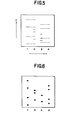
- Figure 5 schematically shows an autoradiograph of electrophretically resolved pattern consisting of the above-mentioned four groups of radioactively labeled base specific cleavage products. That is, rows of from the first to fourth shown in Figure 5 in order correspond to:
- the stimulable phosphor sheet on which the autoradiograph is copied then is installed on the read-out system shown in Figure 1 to carry out the read-out operation, and the digital signal corresponding to the autoradiograph is obtained.
- the obtained digital signal is subjected to the digital signal processing in the signal processing circuit 26 as mentioned above.
- the scanning line for the signal processing for the four rows given in the autoradiograph is respectively determined by the digital signal processing in the same manner as aforementioned. For instance, a line passing over the X-coordinate (X a ) and being parallel to Y-axis is assigned to the scanning line for each row, wherein a is a positive integer and represents the number of each row.
- sampling point S an having a coordinate and a signal level at its coordinate (X a , Y an , Z ) is determined for each row, wherein n is an integer and represents the number of each sampling point.
- the above-mentioned four rows are rearranged. That is, using the first row having the sampling points S 1n represented by (X 1 , Y 1n' Z 1n ) and the second row having the sampling points S 2n represent- ed by ( X 2 , Y 2n' Z 2n ), the following calculation is done: to form a new set of ⁇ Y 5n ⁇ according to the fact that a set of Y-coordinates ⁇ Y 1n ⁇ of the sampling points in the first row is included in a set of ⁇ Y 2n ⁇ of the sampling points in the second row.
- an imaginary fifth row having sampling points S 5n re p resented by (Y 5n , Z 5n ) is obtained.
- the obtained fifth row has the locational information on adenine (A) alone.
- the same calculation as mentioned above are performed between the third row having the sampling points S 3n represented by (X 3 , Y 3n' Z 3n ) and the fourth row having the sampling points S 4n represented by (X 4 , Y 4n' Z 4n ) ' to obtain an imaginary sixth row having sampling points S 6n represented by (Y 6n , Z 6n ) '
- the sixth row has the locational information on thymine (T) alone.
- T thymine
- Figure 6 illustrates the locational information on the above four rows rearranged through the above calculation.
- these four rows are compared with each other with respect to the position (Y ) to arrange the sampling points in the order of from the farthest position to the starting position. For instance, the following scheme is obtained:
- the base sequence of one chain molecule of DNA can be determined.
- the representation mode of the obtained information on the base sequence of DNA is by no means limited to the above-mentioned mode, and any other representation mode may be utilized optionally.
- the signal level (2 ) at the sampling point in the above-mentioned signal processing can be represented bys the relative amount of each cleavage product resolved. Otherwise, the illustrative representation as shown in Figure 6 is also possible.
- the base sequence of two chain molecules of DNA can be represented in combination. That is, by giving the information on the combination between the four bases, namely A-T and G-C, the base sequence of DNA represented by the following scheme is obtained:
- the method for determining the base sequence of DNA utilizing the above-mentioned combination is an example of the determination of the base sequence of DNA.
- the signal processing of the present invention is by no means limited to the above-mentioned combination, and various combinations are employable and the base sequence of DNA can be determined by applying thereto the corresponding method in the same manner as described above.
- the set or combination (G, A, T, C) can be employed to determine the base sequence of DNA.
- the combination of at least one group of base specific cleavage products and a suitable reference substance for example, a mixture of all base specific cleavage products
- a suitable reference substance for example, a mixture of all base specific cleavage products
- the present invention was described by using four rows of the radioactively labeled products resolved one-dimensionally on a support medium, but the number of the resolved rows is by no means limited to four, and may be more or less. Further, the base sequence of two or more of DNA can be determined simultaneously using one support medium.
- the information on the base sequence of DNA determined through the above-mentioned signal processing is output from the signal processing circuit 26, and can be subsequently recorded using the above-mentioned recording devices or the like.
- the digital signal, or the electric signal which has not been A/D-converted to the digital signal can be input to the reproducing device such as one shown in Figure 4 and subsequently reproduced on the photosensitive material such as a photographic film as described above.
- the suitable image processing may be applied in advance of the reproduction of the visible image.
Landscapes
- Physics & Mathematics (AREA)
- Health & Medical Sciences (AREA)
- Life Sciences & Earth Sciences (AREA)
- General Physics & Mathematics (AREA)
- High Energy & Nuclear Physics (AREA)
- Molecular Biology (AREA)
- Spectroscopy & Molecular Physics (AREA)
- Measurement Of Radiation (AREA)
- Investigating Or Analysing Biological Materials (AREA)
Applications Claiming Priority (4)
| Application Number | Priority Date | Filing Date | Title |
|---|---|---|---|
| JP58001326A JPS59126527A (ja) | 1983-01-08 | 1983-01-08 | オ−トラジオグラフイ−における信号処理方法 |
| JP1326/83 | 1983-01-08 | ||
| JP58001327A JPS59126528A (ja) | 1983-01-08 | 1983-01-08 | オ−トラジオグラフイ−における信号処理方法 |
| JP1327/83 | 1983-01-08 |
Publications (2)
| Publication Number | Publication Date |
|---|---|
| EP0113672A2 true EP0113672A2 (de) | 1984-07-18 |
| EP0113672A3 EP0113672A3 (de) | 1988-03-02 |
Family
ID=26334542
Family Applications (1)
| Application Number | Title | Priority Date | Filing Date |
|---|---|---|---|
| EP84100144A Withdrawn EP0113672A3 (de) | 1983-01-08 | 1984-01-09 | Signalbearbeitungsmethode in der Autoradiographie |
Country Status (2)
| Country | Link |
|---|---|
| US (1) | US4777597A (de) |
| EP (1) | EP0113672A3 (de) |
Cited By (7)
| Publication number | Priority date | Publication date | Assignee | Title |
|---|---|---|---|---|
| US4720786A (en) * | 1985-04-19 | 1988-01-19 | Fuji Photo Film Co., Ltd. | Method of compensating for offset distortion in rows of electrophoretic patterns |
| EP0160948A3 (de) * | 1984-05-04 | 1989-02-08 | Fuji Photo Film Co., Ltd. | Verfahren zur Signalverarbeitung in der Autoradiographie |
| US4930893A (en) * | 1988-03-25 | 1990-06-05 | Molecular Dynamics | Electrophoresis imaging system |
| US5028793A (en) * | 1985-10-10 | 1991-07-02 | Quantex Corporation | Imaging screen for electrophoresis applications |
| EP0242629B1 (de) * | 1986-03-26 | 1992-08-26 | Fuji Photo Film Co., Ltd. | Signalverarbeitungsmethode zur Bestimmung des Grundaufbaus von Nukleinsäuren |
| US5270162A (en) * | 1983-09-19 | 1993-12-14 | Fuji Photo Film Co., Ltd. | Autoradiographic gene-screening method |
| US9619203B2 (en) | 2003-07-07 | 2017-04-11 | Insurance Services Office, Inc. | Method of analyzing driving behavior and warning the driver |
Families Citing this family (16)
| Publication number | Priority date | Publication date | Assignee | Title |
|---|---|---|---|---|
| JPS6285861A (ja) * | 1985-10-11 | 1987-04-20 | Fuji Photo Film Co Ltd | 核酸の塩基配列決定のための信号処理方法 |
| JPS6285862A (ja) * | 1985-10-11 | 1987-04-20 | Fuji Photo Film Co Ltd | 核酸の塩基配列決定のための信号処理方法 |
| JPS62228165A (ja) * | 1986-03-29 | 1987-10-07 | Fuji Photo Film Co Ltd | 核酸の塩基配列決定のための信号処理方法 |
| JPS63167290A (ja) * | 1986-12-27 | 1988-07-11 | Fuji Photo Film Co Ltd | オ−トラジオグラフ解析のための信号処理方法 |
| JPH0664057B2 (ja) * | 1987-01-06 | 1994-08-22 | 富士写真フイルム株式会社 | オ−トラジオグラフ解析のための信号処理方法 |
| US5525464A (en) * | 1987-04-01 | 1996-06-11 | Hyseq, Inc. | Method of sequencing by hybridization of oligonucleotide probes |
| US5202231A (en) | 1987-04-01 | 1993-04-13 | Drmanac Radoje T | Method of sequencing of genomes by hybridization of oligonucleotide probes |
| US5547839A (en) | 1989-06-07 | 1996-08-20 | Affymax Technologies N.V. | Sequencing of surface immobilized polymers utilizing microflourescence detection |
| DK232090A (da) * | 1990-09-25 | 1992-03-26 | Jydsk Telefon As | Fremgangsmaade og apparat til aftastning af straalingskildefordelingen i et medium, f.eks. proteinfordelingen i en gel |
| US5831275A (en) * | 1994-04-15 | 1998-11-03 | Fuji Photo Film Co., Ltd. | Image forming apparatus |
| US6343142B1 (en) * | 1994-05-20 | 2002-01-29 | Fuji Photo Film Co., Ltd. | Image analyzing apparatus |
| US5795716A (en) | 1994-10-21 | 1998-08-18 | Chee; Mark S. | Computer-aided visualization and analysis system for sequence evaluation |
| US20040175718A1 (en) * | 1995-10-16 | 2004-09-09 | Affymetrix, Inc. | Computer-aided visualization and analysis system for sequence evaluation |
| JP3851699B2 (ja) * | 1997-02-06 | 2006-11-29 | 富士写真フイルム株式会社 | 画像解析装置 |
| FI20086240A7 (fi) * | 2008-12-23 | 2010-06-24 | Palodex Group Oy | Kuvalevyn lukijalaitteen puhdistusjärjestelmä |
| FI20086241A7 (fi) | 2008-12-23 | 2010-06-24 | Palodex Group Oy | Kuvalevyn lukijalaite |
Family Cites Families (12)
| Publication number | Priority date | Publication date | Assignee | Title |
|---|---|---|---|---|
| US31847A (en) * | 1861-03-26 | Jesse young | ||
| USRE31847E (en) | 1973-01-02 | 1985-03-12 | Eastman Kodak Company | Apparatus and method for producing images corresponding to patterns of high energy radiation |
| SU738602A1 (ru) * | 1977-04-11 | 1980-06-05 | Предприятие П/Я В-8657 | Устройство дл анализа электрофореграмм |
| JPS5944333B2 (ja) * | 1978-07-12 | 1984-10-29 | 富士写真フイルム株式会社 | 放射線像変換方法 |
| US4346295A (en) * | 1978-12-26 | 1982-08-24 | Fuji Photo Film Co., Ltd. | Radiation image read out device |
| US4320415A (en) * | 1979-06-14 | 1982-03-16 | National Research Development Corporation | Method of and apparatus for measuring electrophoretic mobility of cells |
| US4317318A (en) * | 1979-09-04 | 1982-03-02 | Roblin Industries, Inc. | Supporting grid system having interchangeable T sections |
| US4315179A (en) * | 1980-04-10 | 1982-02-09 | Westinghouse Electric Corp. | Double layered stator peripheral end windings |
| US4395486A (en) * | 1981-08-19 | 1983-07-26 | Medical College Of Ga. Research Inst., Inc. | Method for the direct analysis of sickle cell anemia |
| US4526865A (en) * | 1981-10-01 | 1985-07-02 | Amb Systems Corp. | Microorganism identification technique |
| JPS5889244A (ja) * | 1981-11-25 | 1983-05-27 | 富士写真フイルム株式会社 | 放射線画像情報読取方法 |
| US4389670A (en) * | 1981-12-30 | 1983-06-21 | The United States Of America As Represented By The United States Department Of Energy | Electronic method for autofluorography of macromolecules on two-D matrices |
-
1984
- 1984-01-09 EP EP84100144A patent/EP0113672A3/de not_active Withdrawn
-
1987
- 1987-03-11 US US07/024,909 patent/US4777597A/en not_active Expired - Lifetime
Cited By (8)
| Publication number | Priority date | Publication date | Assignee | Title |
|---|---|---|---|---|
| US5270162A (en) * | 1983-09-19 | 1993-12-14 | Fuji Photo Film Co., Ltd. | Autoradiographic gene-screening method |
| EP0160948A3 (de) * | 1984-05-04 | 1989-02-08 | Fuji Photo Film Co., Ltd. | Verfahren zur Signalverarbeitung in der Autoradiographie |
| US4720786A (en) * | 1985-04-19 | 1988-01-19 | Fuji Photo Film Co., Ltd. | Method of compensating for offset distortion in rows of electrophoretic patterns |
| US5028793A (en) * | 1985-10-10 | 1991-07-02 | Quantex Corporation | Imaging screen for electrophoresis applications |
| EP0242629B1 (de) * | 1986-03-26 | 1992-08-26 | Fuji Photo Film Co., Ltd. | Signalverarbeitungsmethode zur Bestimmung des Grundaufbaus von Nukleinsäuren |
| EP0476712B1 (de) * | 1986-03-26 | 1995-06-21 | Fuji Photo Film Co., Ltd. | Signalverarbeitungsmethode zur Bestimmung des Grundaufbaus von Nukleinsäuren |
| US4930893A (en) * | 1988-03-25 | 1990-06-05 | Molecular Dynamics | Electrophoresis imaging system |
| US9619203B2 (en) | 2003-07-07 | 2017-04-11 | Insurance Services Office, Inc. | Method of analyzing driving behavior and warning the driver |
Also Published As
| Publication number | Publication date |
|---|---|
| EP0113672A3 (de) | 1988-03-02 |
| US4777597A (en) | 1988-10-11 |
Similar Documents
| Publication | Publication Date | Title |
|---|---|---|
| US4777597A (en) | Signal processing method in autoradiography | |
| US4837733A (en) | Signal processing method in autoradiography | |
| EP0123942B1 (de) | Verfahren zur Erfassung von Signalen in der Autoradiographie | |
| US4888695A (en) | Signal processing method in autoradiography | |
| EP0123943B1 (de) | Verfahren zur Erfassung von Signalen in der Autoradiographie | |
| US4894786A (en) | Signal processing method for analyzing autoradiograph | |
| US4734581A (en) | Autoradiographic process | |
| US4852050A (en) | Signal processing method in autoradiography | |
| US4958281A (en) | Signal processing method for determining base sequence of nucleic acid | |
| US4871913A (en) | Signal processing method in autoradiography | |
| US4862358A (en) | Signal processing method in autoradiography | |
| US4868746A (en) | Signal processing method in autoradiography | |
| US4868749A (en) | Signal processing method in autoradiography | |
| US4862360A (en) | Signal processing method in autoradiography | |
| US6343142B1 (en) | Image analyzing apparatus | |
| JPH0259954B2 (de) | ||
| JPH0259953B2 (de) | ||
| JP3571801B2 (ja) | 画像解析装置 | |
| JPH0259956B2 (de) | ||
| JPS60233557A (ja) | オ−トラジオグラフイ−における信号処理方法 | |
| EP0252182A1 (de) | Verfahren zum Zeigen einer Autoradiographie | |
| JPS59182362A (ja) | オ−トラジオグラフイ−における信号処理方法 | |
| JPH0259955B2 (de) | ||
| JPS59126280A (ja) | オ−トラジオグラフイ−における信号処理法 | |
| JPS59126247A (ja) | オ−トラジオグラフイ−における信号処理方法 |
Legal Events
| Date | Code | Title | Description |
|---|---|---|---|
| PUAI | Public reference made under article 153(3) epc to a published international application that has entered the european phase |
Free format text: ORIGINAL CODE: 0009012 |
|
| AK | Designated contracting states |
Designated state(s): CH DE FR LI NL SE |
|
| PUAL | Search report despatched |
Free format text: ORIGINAL CODE: 0009013 |
|
| AK | Designated contracting states |
Kind code of ref document: A3 Designated state(s): CH DE FR LI NL SE |
|
| 17P | Request for examination filed |
Effective date: 19880421 |
|
| 17Q | First examination report despatched |
Effective date: 19891213 |
|
| 18D | Application deemed to be withdrawn |
Effective date: 19900911 |
|
| STAA | Information on the status of an ep patent application or granted ep patent |
Free format text: STATUS: THE APPLICATION IS DEEMED TO BE WITHDRAWN |
|
| R18D | Application deemed to be withdrawn (corrected) |
Effective date: 19900424 |
|
| RIN1 | Information on inventor provided before grant (corrected) |
Inventor name: KIMURA, TSUTOMU Inventor name: HISHINUMA, KAZUHIRO Inventor name: SHIRAISHI, HISASHI |