EP0113855A1 - Système d'éclairage de plafond à puissance limitée pour lampes fluorescentes - Google Patents
Système d'éclairage de plafond à puissance limitée pour lampes fluorescentes Download PDFInfo
- Publication number
- EP0113855A1 EP0113855A1 EP19830112323 EP83112323A EP0113855A1 EP 0113855 A1 EP0113855 A1 EP 0113855A1 EP 19830112323 EP19830112323 EP 19830112323 EP 83112323 A EP83112323 A EP 83112323A EP 0113855 A1 EP0113855 A1 EP 0113855A1
- Authority
- EP
- European Patent Office
- Prior art keywords
- power
- lighting
- voltage
- limited
- operative
- Prior art date
- Legal status (The legal status is an assumption and is not a legal conclusion. Google has not performed a legal analysis and makes no representation as to the accuracy of the status listed.)
- Withdrawn
Links
- 238000006243 chemical reaction Methods 0.000 claims 2
- 230000000977 initiatory effect Effects 0.000 claims 2
- 239000004020 conductor Substances 0.000 abstract description 20
- 230000001939 inductive effect Effects 0.000 abstract description 12
- 239000003990 capacitor Substances 0.000 description 19
- 238000004804 winding Methods 0.000 description 12
- 238000002955 isolation Methods 0.000 description 8
- 238000010438 heat treatment Methods 0.000 description 6
- 238000010276 construction Methods 0.000 description 3
- 230000000694 effects Effects 0.000 description 2
- 238000005286 illumination Methods 0.000 description 2
- 238000009434 installation Methods 0.000 description 2
- 238000006073 displacement reaction Methods 0.000 description 1
- 230000003993 interaction Effects 0.000 description 1
- 230000000063 preceeding effect Effects 0.000 description 1
- 230000005855 radiation Effects 0.000 description 1
- 230000035939 shock Effects 0.000 description 1
Images


Classifications
-
- H—ELECTRICITY
- H05—ELECTRIC TECHNIQUES NOT OTHERWISE PROVIDED FOR
- H05B—ELECTRIC HEATING; ELECTRIC LIGHT SOURCES NOT OTHERWISE PROVIDED FOR; CIRCUIT ARRANGEMENTS FOR ELECTRIC LIGHT SOURCES, IN GENERAL
- H05B41/00—Circuit arrangements or apparatus for igniting or operating discharge lamps
- H05B41/14—Circuit arrangements
- H05B41/24—Circuit arrangements in which the lamp is fed by high frequency AC, or with separate oscillator frequency
- H05B41/245—Circuit arrangements in which the lamp is fed by high frequency AC, or with separate oscillator frequency for a plurality of lamps
-
- H—ELECTRICITY
- H05—ELECTRIC TECHNIQUES NOT OTHERWISE PROVIDED FOR
- H05B—ELECTRIC HEATING; ELECTRIC LIGHT SOURCES NOT OTHERWISE PROVIDED FOR; CIRCUIT ARRANGEMENTS FOR ELECTRIC LIGHT SOURCES, IN GENERAL
- H05B41/00—Circuit arrangements or apparatus for igniting or operating discharge lamps
Definitions
- the present invention relates to power-line-operated low-voltage limited-power fluorescent lighting systems.
- Class 2 transformers are strictly limited in maximum voltage (30 Volt RMS), maximum rated Volt-Amperes (100 VA) and maximum current (8 Amp RMS); and would not appear to yield enough power to provide an amount of illumination that would be considered adequate in a substantial number of ordinary lighting system installations.
- a Class 2 transformer does have enough power potentially available to provide for an amount of illumination that is nearly equal to that normally obtained from one of the commonly used four-lamp fluorescent ceiling fixtures.
- a first object of the present invention is that of providing a high-efficiency easy-to-install fluorescent lighting system.
- a second object is that of providing a fluorescent lighting system that is particularly adapted to be used with suspended ceiling systems and that can readily and safely be installed by persons of-but ordinary skills.
- a third object is that of providing means by which fluorescent lighting fixtures can safely and easily be installed and/or removed by the do-it-yourself'er without requiring the assistance of an electrician.
- Subject invention relates to a high-frequenoy, low-voltage, limited-power (Class 2) fluorescent lighting system and consists of the following principal component parts:
- each lighting unit is provided at a high power factor, thereby (under the Class 2 provisions of the National Electrical Code) permitting a power level of nearly 100 Watt to be provided to each lighting unit; which, with the indicated high frequency operation and with presently available high-efficacy fluorescent lamps, can provide for a light output of about 10,000 Lumens per lighting unit.
- a source S of 120Volt/60Hz voltage is applied to a pair of power line conductors PL1 and PL2.
- n n of fluorescent lighting units LU1, LU2 ---LUn.
- the number n may be different for different power supplies and/or at different times.
- Fig. 2 illustrates in further detail one of the power supplies of Fig. 1 and its associated n lighting units.
- This one power supply is referred to as PSx, and is powered from power line conductors PL1 and PL2.
- power line conductors PL1 and PL2 are directly connected with a rectifier-filter combination RF, the substantially constant DC output voltage of which is applied to an inverter I.
- the output from inverter I is a 30 kHz AC voltage, which AC voltage is applied to the primary winding Tp of an isolation transformer T.
- transformer T The output of transformer T is provided from its secondary winding Ts and is a 30 kHz AC voltage of approximately 30 Volt RMS magnitude. Secondary winding Ts is electrically isolated from primary winding Tp.
- this transformer output voltage is supplied to a number n of power output receptacles OR1, OR2 --- ORn, all respectively.
- the output receptacles OR1, OR2 --- ORn are connected with input receptacles IR1, IR2 --- IRn on fluorescent lighting units LU1, LU2 --- LUn, all respectively.
- the assembly consisting of rectifier and filter means RF, inverter I, transformer T and the n output receptacles OR1, OR2 --- ORn, is referred to as power supply PSx.
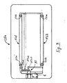
- Fig. 3 illustrates one of the n lighting units referred to in Fig. 2 as LU1, LU2 -- LUn. This one lighting unit is referred to as LUx and has a power input receptacle IRx.
- a voltage-step-up auto-transformer AT Inside lighting unit LUx is a voltage-step-up auto-transformer AT, the input side of which is directly connected with input receptacle IRx and the output side of which is directly connected across a series-combination of two fluorescent lamps FL1 and FL2.
- Fluorescent lamp FL1 has two cathodes C1a and C1b; and fluorescent lamp FL2 has two cathodes C2a and C2b.
- Auto-transformer AT has three secondary windings ATsl, ATs2 and ATs3, all of which are electrically isolated from one another as well as from the input side of auto-transformer AT.
- Secondary winding ATs1 is directly connected with cathode C1a; secondary winding ATs2 is directly connected with a parallel-connection of cathodes C1b and C2a; and secondary winding ATs3 is directly connected with cathode C2b.
- a capacitor C is connected directly across the output side of auto-transformer AT.
- the pair of power line conductors PL1 and PL2 provides t20Volt/60Hz power to each and every inverter power supply: PS1, PS2 --- PSm.
- Each and every inverter power supply converts its 120Volt/60Hz input voltage to a plurality of power-line-isolated power-limited high-frequency low-magnitude AC voltage outputs; and each such AC voltage output is directly connected with a fluorescent lighting unit -- powering this fluorescent lighting unit by way of said power-limited high-frequency low-magnitude AC voltage.
- Fig. 2 shows how said power-line-isolated power-limited high-frequency low-magnitude AC voltage outputs are obtained.
- the 120Volt/60Hz power line voltage is applied to a rectifier-filter combination of conventional construction; and the output from this.
- rectifier-filter combination is a substantially constant DC voltage.
- This DC voltage is inverted by conventional inverter I to a 30 kHz AC voltage of essentially squarewave shape.
- This 30 kHz squarewave inverter output voltage is applied to the primary winding of voltage-step-down high-frequency transformer T; which transformer is of conventional construction.
- This transformer also provides for electrical isolation between its primary and secondary windings, thereby providing for the requisite power-line-isolation of the AC voltage outputs from power supply PSx.
- the output of the secondary winding Ts of transformer T is a 30 kHz non-power-limited essentially squarewave-shaped AC voltage with a substantially constant RMS magnitude of about 30 Volt; which AC voltage is provided to the n power output receptacles P01, P02 --- POn of power supply PSx by way of n inductors L1, L2 --- Ln.
- the magnitude of the current available at any one of these power output receptacles is limited by the reactance of the inductor connected in series circuit with that receptacle.
- the magnitude of the reactance of this inductor is chosen such that the current resulting when a given output receptacle is short-circuited is no higher than 8 Amp RMS.
- Fig. 3 shows how the individual lighting units work and more particularly, how the ballasting of the fluorescent lamps is accomplished.
- the outout from one of the output receptacles of power supply PSx is applied by way of a conduction wire-pair to power input receptacle IRx of lighting unit LUx, from where it is applied directly to a voltage step-up transformer AT, the output of which is applied directly across two series-connected fluorescent lamps.
- the actual ballasting of the two fluorescent lamps is accomplished by way of resonant interaction between the capacitor (which is connected in parallel across the two series-connected fluorescent lamps) and the particular inductor located in the power supply feeding power to the lighting unit LUx.
- part of the ballasting function for the two fluorescent lamps of lighting unit LUx is accomplished by way of one of the inductors within the power supply PSx.
- any one of the lighting units may consist of any number of fluorescent lamps; and that these fluorescent lamps might even be mounted in different locations and/or located in different lighting structures and/or fixtures.
- the current drawn from the inverter power supplies by the different lighting units will be nearly sinusoidal in waveshape; and it will be substantially in phase with the fundamental component of the squarewave AC voltage outputs provided by these power supplies.
- the power drawn by the lighting units is drawn with a high power factor, which implies a maximization of the power available within a set limit of Volt-Amperes.
- resulting electromagnetic interference by radiation from lamps and/or conductor wires is minimized.
- capacitor C which is shown in Fig. 3 as being connected across the secondary side of transformer AT, may just as well be connected across the primary side of said transformer. In fact, to provide for the desired power factor correction, the capacitor may even be connected in series with the output or input side of said transformer.
- the lighting units may comprise incandescent lamps.
- the invention may be summarized as follows:
Landscapes
- Circuit Arrangements For Discharge Lamps (AREA)
Applications Claiming Priority (2)
| Application Number | Priority Date | Filing Date | Title |
|---|---|---|---|
| US45018782A | 1982-12-16 | 1982-12-16 | |
| US450187 | 1982-12-16 |
Publications (1)
| Publication Number | Publication Date |
|---|---|
| EP0113855A1 true EP0113855A1 (fr) | 1984-07-25 |
Family
ID=23787127
Family Applications (1)
| Application Number | Title | Priority Date | Filing Date |
|---|---|---|---|
| EP19830112323 Withdrawn EP0113855A1 (fr) | 1982-12-16 | 1983-12-07 | Système d'éclairage de plafond à puissance limitée pour lampes fluorescentes |
Country Status (1)
| Country | Link |
|---|---|
| EP (1) | EP0113855A1 (fr) |
Cited By (5)
| Publication number | Priority date | Publication date | Assignee | Title |
|---|---|---|---|---|
| GB2171858A (en) * | 1985-03-02 | 1986-09-03 | British Steel Corp | Improvements in lighting systems |
| GB2261332A (en) * | 1991-11-06 | 1993-05-12 | Horizon Fabrications Ltd | Driving circuits for discharge devices |
| FR2732541A1 (fr) * | 1995-04-03 | 1996-10-04 | Solar Wide Ind Ltd | Dispositifs d'eclairage pour l'alimentation de plusieurs lampes fluorescentes |
| GB2299659A (en) * | 1995-04-03 | 1996-10-09 | Solar Wide Ind Ltd | Lighting systems |
| WO2004057928A1 (fr) * | 2002-12-20 | 2004-07-08 | E.D.P. S.R.L. | Systeme destine a controler et reguler continument le flux lumineux de chaque lampe derivee unique sur une ligne parallele |
Citations (5)
| Publication number | Priority date | Publication date | Assignee | Title |
|---|---|---|---|---|
| DE2705969A1 (de) * | 1976-03-01 | 1977-09-08 | Gen Electric | Vorschaltanordnung fuer entladungslampe |
| GB2021335A (en) * | 1978-05-22 | 1979-11-28 | Gte Sylvania Inc | Direct drive ballast circuit |
| DE3025629A1 (de) * | 1979-07-09 | 1981-01-29 | Gte Prod Corp | Schaltungsanordnung fuer ein vorschaltgeraet fuer gasentladungslampen |
| EP0027039A2 (fr) * | 1979-10-05 | 1981-04-15 | Victor Products Plc | Systèmes d'alimentation en courant électrique pour emplacements dangereux |
| DE2941822A1 (de) * | 1979-10-16 | 1981-04-30 | Patra Patent Treuhand | Vorschaltanordnung zum betreiben von niederdruckentladungslampen |
-
1983
- 1983-12-07 EP EP19830112323 patent/EP0113855A1/fr not_active Withdrawn
Patent Citations (5)
| Publication number | Priority date | Publication date | Assignee | Title |
|---|---|---|---|---|
| DE2705969A1 (de) * | 1976-03-01 | 1977-09-08 | Gen Electric | Vorschaltanordnung fuer entladungslampe |
| GB2021335A (en) * | 1978-05-22 | 1979-11-28 | Gte Sylvania Inc | Direct drive ballast circuit |
| DE3025629A1 (de) * | 1979-07-09 | 1981-01-29 | Gte Prod Corp | Schaltungsanordnung fuer ein vorschaltgeraet fuer gasentladungslampen |
| EP0027039A2 (fr) * | 1979-10-05 | 1981-04-15 | Victor Products Plc | Systèmes d'alimentation en courant électrique pour emplacements dangereux |
| DE2941822A1 (de) * | 1979-10-16 | 1981-04-30 | Patra Patent Treuhand | Vorschaltanordnung zum betreiben von niederdruckentladungslampen |
Cited By (7)
| Publication number | Priority date | Publication date | Assignee | Title |
|---|---|---|---|---|
| GB2171858A (en) * | 1985-03-02 | 1986-09-03 | British Steel Corp | Improvements in lighting systems |
| GB2261332A (en) * | 1991-11-06 | 1993-05-12 | Horizon Fabrications Ltd | Driving circuits for discharge devices |
| GB2261332B (en) * | 1991-11-06 | 1996-05-08 | Horizon Fabrications Ltd | Driving circuit for electrical discharge devices |
| FR2732541A1 (fr) * | 1995-04-03 | 1996-10-04 | Solar Wide Ind Ltd | Dispositifs d'eclairage pour l'alimentation de plusieurs lampes fluorescentes |
| GB2299659A (en) * | 1995-04-03 | 1996-10-09 | Solar Wide Ind Ltd | Lighting systems |
| NL1002784C2 (nl) * | 1995-04-03 | 1997-11-06 | Solar Wide Ind Ltd | Verlichtingssysteem. |
| WO2004057928A1 (fr) * | 2002-12-20 | 2004-07-08 | E.D.P. S.R.L. | Systeme destine a controler et reguler continument le flux lumineux de chaque lampe derivee unique sur une ligne parallele |
Similar Documents
| Publication | Publication Date | Title |
|---|---|---|
| US5047696A (en) | Power-limited ceiling lighting system | |
| US5003227A (en) | Power distribution for lighting systems | |
| US4667133A (en) | Power-limited lighting system | |
| US5479326A (en) | Ceiling system with readily movable lighting panels | |
| US5691603A (en) | Electronic ballast with multiple lamp loads | |
| US5640069A (en) | Modular lighting system | |
| US7746003B2 (en) | Transformer wiring method and apparatus for fluorescent lighting | |
| US5426347A (en) | Lighting system with emergency standby feature | |
| US6515437B1 (en) | Power supply for hybrid illumination system | |
| US6100643A (en) | Modular electronic lighting system | |
| US4626747A (en) | Class-3 lighting system | |
| US4866757A (en) | Combined telephone and power distribution system | |
| AU641108B2 (en) | AC power conditioning circuit | |
| US6300725B1 (en) | Power supply for hybrid illumination system | |
| JPS62290917A (ja) | 力率改善回路網 | |
| WO1994027419A1 (fr) | Systeme et procede d'alimentation en courant de lampe a decharge | |
| US4651059A (en) | High-frequency power-limited lighting system | |
| US4626953A (en) | Doubly overload-protected power distribution system | |
| US5998936A (en) | Fire-initiation-safe lighting system | |
| US6906474B2 (en) | Three-phase electronic ballast | |
| US6144445A (en) | Electronic ballast products and systems | |
| US5262700A (en) | Fluorescent lighting means | |
| US3906243A (en) | Retrofit emergency lighting system | |
| US20040232775A1 (en) | Lighting system comprised of a unique direct current power supply and a plurality of gas discharge luminaires | |
| US4798998A (en) | Electronically dimmed power limited lighting system |
Legal Events
| Date | Code | Title | Description |
|---|---|---|---|
| PUAI | Public reference made under article 153(3) epc to a published international application that has entered the european phase |
Free format text: ORIGINAL CODE: 0009012 |
|
| AK | Designated contracting states |
Designated state(s): DE FR GB |
|
| 17P | Request for examination filed |
Effective date: 19850102 |
|
| 17Q | First examination report despatched |
Effective date: 19860915 |
|
| STAA | Information on the status of an ep patent application or granted ep patent |
Free format text: STATUS: THE APPLICATION IS DEEMED TO BE WITHDRAWN |
|
| 18D | Application deemed to be withdrawn |
Effective date: 19870127 |