EP0113968A1 - Vorrichtung zur Handhabung von Material - Google Patents
Vorrichtung zur Handhabung von Material Download PDFInfo
- Publication number
- EP0113968A1 EP0113968A1 EP83307517A EP83307517A EP0113968A1 EP 0113968 A1 EP0113968 A1 EP 0113968A1 EP 83307517 A EP83307517 A EP 83307517A EP 83307517 A EP83307517 A EP 83307517A EP 0113968 A1 EP0113968 A1 EP 0113968A1
- Authority
- EP
- European Patent Office
- Prior art keywords
- conveyor
- run
- belt
- elevator
- belt conveyor
- Prior art date
- Legal status (The legal status is an assumption and is not a legal conclusion. Google has not performed a legal analysis and makes no representation as to the accuracy of the status listed.)
- Granted
Links
- 239000000463 material Substances 0.000 title claims abstract description 78
- 238000000034 method Methods 0.000 claims abstract description 6
- 238000000151 deposition Methods 0.000 claims description 5
- 230000000717 retained effect Effects 0.000 claims description 3
- 239000011236 particulate material Substances 0.000 abstract description 6
- 238000007790 scraping Methods 0.000 abstract description 2
- 239000000428 dust Substances 0.000 description 10
- 239000011521 glass Substances 0.000 description 5
- 239000004744 fabric Substances 0.000 description 4
- 239000006063 cullet Substances 0.000 description 3
- 238000004519 manufacturing process Methods 0.000 description 3
- 230000000694 effects Effects 0.000 description 2
- 239000002184 metal Substances 0.000 description 2
- 230000002093 peripheral effect Effects 0.000 description 2
- 239000002994 raw material Substances 0.000 description 2
- 229910000831 Steel Inorganic materials 0.000 description 1
- 230000015572 biosynthetic process Effects 0.000 description 1
- 239000004568 cement Substances 0.000 description 1
- 239000003245 coal Substances 0.000 description 1
- 230000001419 dependent effect Effects 0.000 description 1
- 238000000605 extraction Methods 0.000 description 1
- 238000005816 glass manufacturing process Methods 0.000 description 1
- 230000005484 gravity Effects 0.000 description 1
- 229910052500 inorganic mineral Inorganic materials 0.000 description 1
- 238000005007 materials handling Methods 0.000 description 1
- 239000011707 mineral Substances 0.000 description 1
- 238000005065 mining Methods 0.000 description 1
- 239000000203 mixture Substances 0.000 description 1
- 239000002245 particle Substances 0.000 description 1
- 239000004033 plastic Substances 0.000 description 1
- 229920003023 plastic Polymers 0.000 description 1
- 238000004064 recycling Methods 0.000 description 1
- 150000003839 salts Chemical class 0.000 description 1
- 239000007787 solid Substances 0.000 description 1
- 239000010959 steel Substances 0.000 description 1
- 239000000126 substance Substances 0.000 description 1
Images


Classifications
-
- B—PERFORMING OPERATIONS; TRANSPORTING
- B65—CONVEYING; PACKING; STORING; HANDLING THIN OR FILAMENTARY MATERIAL
- B65G—TRANSPORT OR STORAGE DEVICES, e.g. CONVEYORS FOR LOADING OR TIPPING, SHOP CONVEYOR SYSTEMS OR PNEUMATIC TUBE CONVEYORS
- B65G45/00—Lubricating, cleaning, or clearing devices
- B65G45/10—Cleaning devices
- B65G45/26—Cleaning devices for gathering residue after cleaning
-
- B—PERFORMING OPERATIONS; TRANSPORTING
- B65—CONVEYING; PACKING; STORING; HANDLING THIN OR FILAMENTARY MATERIAL
- B65G—TRANSPORT OR STORAGE DEVICES, e.g. CONVEYORS FOR LOADING OR TIPPING, SHOP CONVEYOR SYSTEMS OR PNEUMATIC TUBE CONVEYORS
- B65G29/00—Rotary conveyors, e.g. rotating discs, arms, star-wheels or cones
- B65G29/02—Rotary conveyors, e.g. rotating discs, arms, star-wheels or cones for inclined or vertical transit
Definitions
- the present invention relates to a method of and apparatus for handling material, and more particularly to a method and apparatus for collecting material which drops off the return run of a continuous conveyor belt and returning that material to the carrying run of the conveyor belt.
- Raw materials for use in industrial processes are commonly conveyed along the carrying runs, commonly the upper runs, of continuous conveyor belts. If the material being conveyed is a particulate material a portion of that material may adhere to the belt and be conveyed along the return run of the belt which is usually the lower run. Some of the adhered material may then become dislodged from the return run by a combination of the effect of gravity, if it is a lower run, and vibration of the return run as it is guided and conveyed under or over under rollers, as well as the dislodging effect of those rollers.
- Types of material which tend to adhere to the carrying run of a continuous conveyor belt include batch materials used in a variety of industrial processes, such as the raw materials used in the glass and chemical industries, and materials produced by mineral extraction industries (e.g. in mining and quarrying). Also particulate materials which are manufactured during an industrial process for example sugar or salt, or materials rejected for recycling, such as glass in the form of cullet. All these materials tend to adhere to a conveyor belt.
- United Kingdom Patent Specification No. 1,405,750 describes a belt cleaner device employing scraper blades mounted for movement along a stationary continuous trough beneath a section of a continuous belt conveyor. The blades scrape material from the underside of the return run of the belt conveyor and scrape against the surface of the trough conveying the material to a position where the material is discharged onto the upper carrying run of the belt conveyor.
- Such a belt cleaner suffers from the disadvantages that there is considerable wear on the underside of the belt, on the blades themselves and on the trough walls. Furthermore, much energy is used in operating such a device because of the frictional forces.
- the present invention provides a method of handling material conveyed along the upper carrying run of a continuous belt conveyor and including collecting at a collection location material which adheres to the belt along its carrying run and is dislodged from the underside of the return run of the belt.
- the collected material is conveyed to a position where the collected material is discharged back onto the carrying run of the belt conveyor, by a movable member disposed around and adjacent to a support roller over which passes the underside of the return belt run and which movable member is not in contact with the underside of the return belt run.
- the movable member is preferably an elevator surrounding a section of the belt conveyor at the position of the first support roller for the return belt run.
- the elevator has a channel section into which material from the return run of the belt conveyor is caught and subsequently transported to a higher position from which the material is discharged back onto the upper carrying run of the conveyor belt.
- the elevator may be circular of non-circular.
- the elevator is a circular wheel which is driven either directly from a motor driven support drum or indirectly from the conveyor belt.
- elevator Any other suitable forms of elevator may be used.
- a screw conveyor either motor driven or indirectly driven from the conveyor belt, or a conveyor which has lifting components that are driven electro-magnetically within a hollow tube.
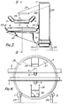
- Figures 1 and 2 illustrate a first embodiment of materials handling apparatus of the invention mounted around a belt conveyor.
- the apparatus includes an elevator wheel 1 made of metal, plastics material or glass reinforced cement mounted around a transverse section of a continuous belt conveyor having an upper carrying belt run 2 and a lower return belt run 3.
- the upper carrying belt run 2 is carried and transported by sets of rollers 4 which shape the belt run 2 into a channel-shaped cross-section for retaining material during its transportation.
- the lower return run 3 passes over support rollers 5.
- the elevator wheel 1 is mounted around the conveyor where the first support roller 5 of the return run is situated and is supported by a driven drum 6 and an idler drum 7.
- the driven drum 6 drives the wheel in a clockwise direction around the conveyor 4, as indicated by arrow A, by the engagement of the driven drum 6 with the outer cylindrical wall 8 of the elevator wheel 2.
- the drums 6 and 7 together support the weight of the elevator wheel 2.
- the rim of the wheel 1 is of U-section formation with two side walls 9 and 10 which extend radially inwardly from the edges of the peripheral wall 8, so that the rim of the wheel is in the form of a continuous U-shaped channel 11 for receiving material falling from the conveyor.
- lifting walls 12 extend transversely across the channel 11, to define a number of troughs in the channel 11 for collecting material which has become dislodged from the lower return run 3 of the conveyor belt in the vicinity of the first support roller 5.
- the driven drum 6 is carried by a pair of brackets 13, and the idler drum 7 is carried by a pair of brackets 14.
- Metal dust guards 15 and 16 are fixed across the wheel between the brackets 13 and 14. As shown in Figure 2, the dust guard 15 has an arcuate lower edge 17 which extends downwardly just into the channel 11 and is in-turned to avoid undue contact with the inner edge of adjacent side wall 10.
- the dust guard 16 is similarly shaped with an arcuate, in-turned lower edge 18.
- a chute 19 is mounted above the upper run 2 of the conveyor to receive material which has been conveyed upwardly by the troughs in the wheel and tipped into the chute 19 which discharges onto the upper belt run 2.
- Formed integrally with the chute 19 are depending side channels 20 which have a U-shaped cross-section and the side walls 21 of which overlap the side walls 9 and 10 of the rim of the wheel 1. Any material which falls out of a trough in the wheel rim before that trough is over the chute 19 falls down one of the side channels 20 back into another of the troughs in the wheel rim lower down the wheel 1.
- the chute 19 is at an angle of at least 45 0 to the horizontal, and preferably at least at 70 0 to the horizontal, to ensure that the slope of the chute 26 is greater than the expected angle of repose for the material being conveyed. This avoids any tendency for material to stick to the chute.
- the angle of repose of a particulate material is dependent on the size, shape and moisture content of that material. Generally the smaller the size of the particulate material so the greater its angle of repose and the greater the required inclination of the chute. For particulate material including a mixture of glass cullet dust of particle sizes from 1200 m to 45 m, the angle of repose and hence the desired inclination of the chute to the horizontal has been found to be at least 70 0.
- the inclination of the lifting walls 12 to the peripheral wall 8 of the channel that is the angle of the lifting walls 12 to their direction of movement, is geometrically matched to the inclination and disposition of the chute 19 to allow the material carried in the rim of the wheel to be retained by each lifting wall 12 until that lifting wall 12 is above the chute 19.
- the side channels 20 are bolted on to the main conveyor structure 22 at their lower ends. In this way the weight of the chute 19 and the side channels 20 is carried by the main conveyor structure 22.
- the upper belt run 2 carries material such as raw batch glass-making material or glass cullet dust, in the direction indicated by arrow B in Figure 2. Some of the material tends to adhere to the conveyor belt and returns along the lower return run 3 of the belt in the direction indicated by arrow C.
- the passage of the lower return run 3 over the first lower support roller 5 just after the belt has passed around the end roller of the conveyor causes vibration which results in dislodgement of some of the material adhering to the lower return run 3 of the belt in the vicinity of the support roller 5.
- the support roller 5 itself also tends to dislodge material off the lower return run 3 of the belt which material falls into the rim channel 11 of the wheel 1.
- the dislodged material falls behind the dust guards 15 and 16 into troughs at the base of the wheel 1, and the material is retained in the troughs by the inclined walls 12 of the wheel 1 as the wheel is rotated in the direction A.
- the elevator wheel 1 may be driven continuously or intermittently by the driven drum 6 depending on the quantities of material dislodged. If the troughs of the wheel channel 11 are particularly full some of the material held within them may spill out before they are above the chute 19. If this occurs the spilt material falls back into lower parts of the wheel channel 11 down the side channels . The material in the troughs is tipped out into the chute 19 directly onto the upper carrying run 2 of the conveyor belt.
- elevator wheels 1 employed at spaced positions along the conveyor where there are support rollers 5.
- the elevator wheel 1 is disposed at the side of the conveyor.
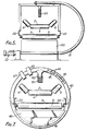
- Detailed features of the apparatus of Figures 3 and 4 correspond to identical features in the handling apparatus of Figures 1 and 2 and are identified by the same reference numerals.
- the feed chute 24 guides material which becomes dislodged from the return belt run 3 through a feed opening 25 into the troughs at the bottom of the elevator wheel 1 which is rotated in a clockwise direction and lifts the material up to a position where it is discharged through a discharge opening 26 of a chute 27 onto the upper run 2 of the conveyor belt.
- wind guards 28 cover both open sides of the wheel 1.
- the elevator wheel 1 is mounted on upstanding legs 29 fitted with rollers. This makes the elevator wheel 1 portable so that it can be moved up and down the main conveyor to selected sites.
- dislodged material from the lower return run 3 of the belt falls into a feed hopper 30, which has downwardly converging walls.
- the base of the hopper 30 feeds the material into the lower portion of a flexible screw conveyor 31 driven by a motor and gearing mounted in a housing 32.
- the flexible screw conveyor 31 feeds the material upwardly to a fabric discharge chute 33 which is disposed directly above the upper carrying run 2 of the belt.
- the fabric discharge chute 33 serves as a wind guard.
- the upper portion of the screw conveyor 31 and the fabric discharge chute 33 are carried by the top member of an inverted U-shaped structure supported on the conveyor structure 22.
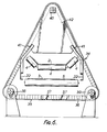
- Figure 6 illustrates another embodiment of the invention in which a flexible U-section trough elevator 34 is disposed around a section of the belt conveyor.
- the channel-section of the elevator 34 is formed by a flexible base belt 35 having flexible side walls 36. Rubber lifting blades 37 (only two of which are shown) are fixed at spaced intervals along the length of the channel section.
- the elevator 34 is driven around two lower pulleys 38 and 39 and over a top supporting drum 40.
- the elevators are driven directly from a motor driven drum or pulley.
- Other forms of drives may be used, for example the elevator can be mechanically driven indirectly from the conveyor belt, and this form of drive is particularly advantageous when there is a need to operate in an environment where electrical discharges must be avoided, such as in a coal mine.
- the mechanical linkages in an indirect drive arrangement may include a belt and pulley arrangement, or a gearbox and a solid drive shaft, or a gearbox and a flexible shaft (like a speedometer cable) connecting one of the support rollers of the conveyor to the drum driving the elevator.
- FIG. 7 A further embodiment is shown in Figure 7 in which an electro-magnetic pulse drive is employed.
- an elevator 43 is in the form of a fixed non-metallic tube formed into a ring surrounding the belt conveyor.
- the inside of the tube is segmented into a number of compartments defined between pairs of spaced steel scraper discs 44 which are slidably mounted within the tube.
- the discs 44 are joined together by means of a non-metallic rope 45 and the rope 45 and discs 44 are held under tension by means of a spring 46.
- a pair of electro-magnetic pulse coils 47 are provided which are pulsed in turn to urge the metallic scraper discs around the tube.
- the tube has an opening 48 at its lower part through which material falls into the compartments within the tube.
- a discharge chute 50 depending from a discharge port in the top of the tube is disposed above the carrying run 2 of the belt conveyor and is provided with a fabric wind guard 51.
- Figures 1 and 2 have the additional advantage that the elevator as a whole moves around or adjacent to the belt conveyor thus eliminating possible wear and tear and frictional forces due to scraping of members against channel walls of the elevator.
Landscapes
- Engineering & Computer Science (AREA)
- Mechanical Engineering (AREA)
- Control And Other Processes For Unpacking Of Materials (AREA)
- Structure Of Belt Conveyors (AREA)
- Branching, Merging, And Special Transfer Between Conveyors (AREA)
- Intermediate Stations On Conveyors (AREA)
- Discharge Of Articles From Conveyors (AREA)
Priority Applications (1)
| Application Number | Priority Date | Filing Date | Title |
|---|---|---|---|
| AT83307517T ATE25649T1 (de) | 1982-12-22 | 1983-12-09 | Vorrichtung zur handhabung von material. |
Applications Claiming Priority (2)
| Application Number | Priority Date | Filing Date | Title |
|---|---|---|---|
| GB8236410 | 1982-12-22 | ||
| GB8236410 | 1982-12-22 |
Publications (2)
| Publication Number | Publication Date |
|---|---|
| EP0113968A1 true EP0113968A1 (de) | 1984-07-25 |
| EP0113968B1 EP0113968B1 (de) | 1987-03-04 |
Family
ID=10535151
Family Applications (1)
| Application Number | Title | Priority Date | Filing Date |
|---|---|---|---|
| EP83307517A Expired EP0113968B1 (de) | 1982-12-22 | 1983-12-09 | Vorrichtung zur Handhabung von Material |
Country Status (6)
| Country | Link |
|---|---|
| US (1) | US4620627A (de) |
| EP (1) | EP0113968B1 (de) |
| AT (1) | ATE25649T1 (de) |
| AU (1) | AU561856B2 (de) |
| DE (1) | DE3369953D1 (de) |
| ZA (1) | ZA839383B (de) |
Cited By (1)
| Publication number | Priority date | Publication date | Assignee | Title |
|---|---|---|---|---|
| NL1009142C2 (nl) * | 1998-05-12 | 1999-11-15 | Oebrabantoe D Van Opstal B V M | Werkwijze en inrichting voor het opvangen en afvoeren van relatief licht materiaal. |
Families Citing this family (17)
| Publication number | Priority date | Publication date | Assignee | Title |
|---|---|---|---|---|
| US5370234A (en) * | 1991-11-08 | 1994-12-06 | National Recovery Technologies, Inc. | Rotary materials separator and method of separating materials |
| RU2357912C1 (ru) * | 2007-12-10 | 2009-06-10 | Федеральное государственное унитарное предприятие "Научно-производственное предприятие "Прогресс" (ФГУП "НПП "Прогресс") | Устройство для уборки просыпи |
| RU2352511C1 (ru) * | 2008-01-09 | 2009-04-20 | Государственное образовательное учреждение высшего профессионального образования "Санкт-Петербургский государственный горный институт имени Г.В. Плеханова (технический университет)" | Устройство для механизированной уборки просыпи из подконвейерного пространства |
| RU2360858C1 (ru) * | 2008-01-09 | 2009-07-10 | Государственное образовательное учреждение высшего профессионального образования "Санкт-Петербургский государственный горный институт имени Г.В. Плеханова (технический университет)" | Устройство для уборки просыпи транспортируемого груза из подконвейерного пространства |
| WO2009126884A1 (en) * | 2008-04-10 | 2009-10-15 | Flexible Steel Lacing Company | Removable cartridge cleaner |
| WO2011106744A1 (en) * | 2010-02-26 | 2011-09-01 | Flexible Steel Lacing Company | Removable cartridge cleaner |
| AU2015283906B2 (en) | 2014-07-04 | 2020-07-09 | Flexible Steel Lacing Company | Conveyor belt cleaner |
| CA3218997A1 (en) | 2021-05-19 | 2022-11-24 | Brett E. Devries | Guided cartridge belt cleaner |
| US11840407B2 (en) | 2021-06-10 | 2023-12-12 | Flexible Steel Lacing Company | Removable cartridge conveyor belt cleaner |
| CN114537967B (zh) * | 2022-03-28 | 2022-11-04 | 江苏驭芯传感器科技有限公司 | 一种带传感器的滚筒流水线 |
| EP4504626A4 (de) | 2022-04-01 | 2026-03-11 | Flexible Steel Lacing Co | Abstreiferklingenhalterung für förderbandreiniger |
| CN117163552B (zh) * | 2022-05-27 | 2026-03-17 | 宝山钢铁股份有限公司 | 一种皮带机撒料的收集及回料装置、皮带机 |
| CN115404087B (zh) * | 2022-09-28 | 2023-07-25 | 洛阳龙泽能源有限公司 | 一种焦粉仓用焦粉回收机构 |
| CN115959463B (zh) * | 2022-12-02 | 2025-12-19 | 西南石油大学 | 一种高处坠落物防冲击保护传递方法 |
| CN119018590B (zh) * | 2024-10-30 | 2025-04-22 | 苏州极味邦食品有限公司 | 一种适用于食品加工的螺旋送料机构 |
| CN119637417B (zh) * | 2025-02-05 | 2025-10-31 | 淮北合众机械设备有限公司 | 一种用于皮带输送机的拍打装置 |
| CN121721041A (zh) * | 2026-02-25 | 2026-03-24 | 晶科能源(海宁)有限公司 | 一种检测设备 |
Citations (7)
| Publication number | Priority date | Publication date | Assignee | Title |
|---|---|---|---|---|
| DD65367A (de) * | ||||
| GB428056A (en) * | 1933-10-28 | 1935-04-29 | Mavor & Coulson Ltd | Improvements in or connected with conveyors of the belt type |
| GB498706A (en) * | 1937-10-20 | 1939-01-12 | Mavor & Coulson Ltd | Improvements in or connected with conveyors of the belt type |
| DE1092836B (de) * | 1958-10-23 | 1960-11-10 | Pohlig Ag J | Aufnahme- und UEbergabevorrichtung fuer das sich insbesondere durch die Wendelung des Banduntertrums unter der Foerderbandanlage ansammelnde Gut |
| GB1405750A (en) * | 1971-07-07 | 1975-09-10 | Dowty Meco Ltd | Belt conveyors |
| DD138055A1 (de) * | 1978-07-19 | 1979-10-10 | Richard Krautheim | Verfahren und vorrichtung zur automatischen bandreinigung und rueckfuehrung der abstreichermassen |
| DE3014042A1 (de) * | 1980-04-11 | 1981-10-15 | Fooke, Heinrich, 4280 Borken | Reinigungsvorrichtung fuer foerderbaender |
Family Cites Families (9)
| Publication number | Priority date | Publication date | Assignee | Title |
|---|---|---|---|---|
| US1863562A (en) * | 1929-10-05 | 1932-06-21 | Structural Gypsum Corp | Belt construction and method of use |
| US2391178A (en) * | 1943-03-11 | 1945-12-18 | Chain Belt Co | Idler roll for belt conveyers |
| US2724493A (en) * | 1952-10-11 | 1955-11-22 | Webster Mfg Inc | Conveyor belt cleaning arrangement |
| NL216520A (de) * | 1956-06-22 | |||
| US3603449A (en) * | 1969-10-06 | 1971-09-07 | Hewitt Robins Inc | Transition structure between conveyor and rotary elevator wheel |
| US3802554A (en) * | 1972-01-24 | 1974-04-09 | Levy E Co | Conveyor belt cleaning device |
| DE2543987A1 (de) * | 1975-10-02 | 1977-04-07 | Halbach & Braun | Feingutfoerderer fuer bandfoerderer, insbesondere feinkohlefoerderer fuer kettenkratzfoerderer |
| FR2388736A1 (fr) * | 1977-04-26 | 1978-11-24 | Philibert Daniel | Dispositif de decolmatage pour convoyeurs a bande sans fin |
| US4280616A (en) * | 1979-03-08 | 1981-07-28 | Wadensten Theodore S | Vibratory belt cleaner with auxiliary vibratory resonance |
-
1983
- 1983-12-09 DE DE8383307517T patent/DE3369953D1/de not_active Expired
- 1983-12-09 AT AT83307517T patent/ATE25649T1/de not_active IP Right Cessation
- 1983-12-09 EP EP83307517A patent/EP0113968B1/de not_active Expired
- 1983-12-19 US US06/562,747 patent/US4620627A/en not_active Expired - Fee Related
- 1983-12-19 ZA ZA839383A patent/ZA839383B/xx unknown
- 1983-12-20 AU AU22563/83A patent/AU561856B2/en not_active Ceased
Patent Citations (7)
| Publication number | Priority date | Publication date | Assignee | Title |
|---|---|---|---|---|
| DD65367A (de) * | ||||
| GB428056A (en) * | 1933-10-28 | 1935-04-29 | Mavor & Coulson Ltd | Improvements in or connected with conveyors of the belt type |
| GB498706A (en) * | 1937-10-20 | 1939-01-12 | Mavor & Coulson Ltd | Improvements in or connected with conveyors of the belt type |
| DE1092836B (de) * | 1958-10-23 | 1960-11-10 | Pohlig Ag J | Aufnahme- und UEbergabevorrichtung fuer das sich insbesondere durch die Wendelung des Banduntertrums unter der Foerderbandanlage ansammelnde Gut |
| GB1405750A (en) * | 1971-07-07 | 1975-09-10 | Dowty Meco Ltd | Belt conveyors |
| DD138055A1 (de) * | 1978-07-19 | 1979-10-10 | Richard Krautheim | Verfahren und vorrichtung zur automatischen bandreinigung und rueckfuehrung der abstreichermassen |
| DE3014042A1 (de) * | 1980-04-11 | 1981-10-15 | Fooke, Heinrich, 4280 Borken | Reinigungsvorrichtung fuer foerderbaender |
Cited By (2)
| Publication number | Priority date | Publication date | Assignee | Title |
|---|---|---|---|---|
| NL1009142C2 (nl) * | 1998-05-12 | 1999-11-15 | Oebrabantoe D Van Opstal B V M | Werkwijze en inrichting voor het opvangen en afvoeren van relatief licht materiaal. |
| EP0959026A1 (de) * | 1998-05-12 | 1999-11-24 | Machinefabriek "Brabant"D. van Opstal B.V. | Verfahren und Vorrichtung zum Sammeln und Entladen von relativ leichtem Material |
Also Published As
| Publication number | Publication date |
|---|---|
| US4620627A (en) | 1986-11-04 |
| AU2256383A (en) | 1984-06-28 |
| AU561856B2 (en) | 1987-05-21 |
| EP0113968B1 (de) | 1987-03-04 |
| DE3369953D1 (en) | 1987-04-09 |
| ATE25649T1 (de) | 1987-03-15 |
| ZA839383B (en) | 1984-09-26 |
Similar Documents
| Publication | Publication Date | Title |
|---|---|---|
| US4620627A (en) | Apparatus for collecting material which becomes dislodged from the underside of a continuous belt conveyor | |
| KR101778362B1 (ko) | 절단스크랩 분리수거장치 | |
| US4068755A (en) | Wet belt conveyor | |
| EP0198685A1 (de) | Maschine zum Aufschlitzen und Entleeren von Säcken | |
| EP3928047B1 (de) | Zuführvorrichtung für eine aufschlämmung | |
| US3280635A (en) | Automatic sampler with scooping-wheel | |
| US2157301A (en) | Conveyer for granular materials | |
| US1958351A (en) | Portable magnetic separator | |
| US5152391A (en) | Hopper feed elevator | |
| US5307922A (en) | Rubber tire individual separation transport apparatus | |
| US20110168606A1 (en) | Run-Of-Mine Coal Separator | |
| CN213894453U (zh) | 一种铁矿石运输用装车装置 | |
| US2571444A (en) | Flight conveyer | |
| EP0089144A1 (de) | Muldenbandförderer | |
| US20250066130A1 (en) | Lifting conveyor belt | |
| GB2124576A (en) | Endless belt conveyor systems | |
| US5423412A (en) | Rubber tire separation and transport apparatus | |
| US2934207A (en) | Machine for feeding and grading pickles or the like | |
| CA1148572A (en) | Discrete parts floor feeder | |
| EP0026993B1 (de) | Elevator | |
| KR20050015504A (ko) | 벨트 컨베이어 설비의 낙하물 자동수집장치 | |
| US3368667A (en) | Means for transporting particulate material | |
| WO1992005095A1 (en) | Method and apparatus for reducing conveyor belt spillage | |
| KR100848631B1 (ko) | 경사벨트컨베이어의 낙석처리장치 | |
| JPH072597Y2 (ja) | 炉室からこぼれ落ちたコークス等の回収装置 |
Legal Events
| Date | Code | Title | Description |
|---|---|---|---|
| PUAI | Public reference made under article 153(3) epc to a published international application that has entered the european phase |
Free format text: ORIGINAL CODE: 0009012 |
|
| AK | Designated contracting states |
Designated state(s): AT BE CH DE FR GB IT LI LU NL SE |
|
| 17P | Request for examination filed |
Effective date: 19850121 |
|
| GRAA | (expected) grant |
Free format text: ORIGINAL CODE: 0009210 |
|
| AK | Designated contracting states |
Kind code of ref document: B1 Designated state(s): AT BE CH DE FR GB IT LI LU NL SE |
|
| PG25 | Lapsed in a contracting state [announced via postgrant information from national office to epo] |
Ref country code: SE Effective date: 19870304 Ref country code: NL Effective date: 19870304 Ref country code: LI Effective date: 19870304 Ref country code: CH Effective date: 19870304 Ref country code: AT Effective date: 19870304 |
|
| REF | Corresponds to: |
Ref document number: 25649 Country of ref document: AT Date of ref document: 19870315 Kind code of ref document: T |
|
| ITF | It: translation for a ep patent filed | ||
| REF | Corresponds to: |
Ref document number: 3369953 Country of ref document: DE Date of ref document: 19870409 |
|
| ET | Fr: translation filed | ||
| REG | Reference to a national code |
Ref country code: CH Ref legal event code: PL |
|
| NLV1 | Nl: lapsed or annulled due to failure to fulfill the requirements of art. 29p and 29m of the patents act | ||
| PG25 | Lapsed in a contracting state [announced via postgrant information from national office to epo] |
Ref country code: LU Free format text: LAPSE BECAUSE OF NON-PAYMENT OF DUE FEES Effective date: 19871231 |
|
| PLBE | No opposition filed within time limit |
Free format text: ORIGINAL CODE: 0009261 |
|
| STAA | Information on the status of an ep patent application or granted ep patent |
Free format text: STATUS: NO OPPOSITION FILED WITHIN TIME LIMIT |
|
| 26N | No opposition filed | ||
| PGFP | Annual fee paid to national office [announced via postgrant information from national office to epo] |
Ref country code: GB Payment date: 19901128 Year of fee payment: 8 |
|
| PGFP | Annual fee paid to national office [announced via postgrant information from national office to epo] |
Ref country code: FR Payment date: 19901129 Year of fee payment: 8 |
|
| ITTA | It: last paid annual fee | ||
| PGFP | Annual fee paid to national office [announced via postgrant information from national office to epo] |
Ref country code: DE Payment date: 19910107 Year of fee payment: 8 |
|
| PGFP | Annual fee paid to national office [announced via postgrant information from national office to epo] |
Ref country code: BE Payment date: 19910214 Year of fee payment: 8 |
|
| PG25 | Lapsed in a contracting state [announced via postgrant information from national office to epo] |
Ref country code: GB Effective date: 19911209 |
|
| PG25 | Lapsed in a contracting state [announced via postgrant information from national office to epo] |
Ref country code: BE Effective date: 19911231 |
|
| BERE | Be: lapsed |
Owner name: PILKINGTON BROTHERS P.L.C. Effective date: 19911231 |
|
| GBPC | Gb: european patent ceased through non-payment of renewal fee | ||
| PG25 | Lapsed in a contracting state [announced via postgrant information from national office to epo] |
Ref country code: FR Effective date: 19920831 |
|
| PG25 | Lapsed in a contracting state [announced via postgrant information from national office to epo] |
Ref country code: DE Effective date: 19920901 |
|
| REG | Reference to a national code |
Ref country code: FR Ref legal event code: ST |