EP0114044A2 - Procédé et dispositif pour le travail à froid d'alésages - Google Patents
Procédé et dispositif pour le travail à froid d'alésages Download PDFInfo
- Publication number
- EP0114044A2 EP0114044A2 EP84100058A EP84100058A EP0114044A2 EP 0114044 A2 EP0114044 A2 EP 0114044A2 EP 84100058 A EP84100058 A EP 84100058A EP 84100058 A EP84100058 A EP 84100058A EP 0114044 A2 EP0114044 A2 EP 0114044A2
- Authority
- EP
- European Patent Office
- Prior art keywords
- mandrel
- pilot
- hole
- split
- coldworking
- Prior art date
- Legal status (The legal status is an assumption and is not a legal conclusion. Google has not performed a legal analysis and makes no representation as to the accuracy of the status listed.)
- Granted
Links
Images

Classifications
-
- B—PERFORMING OPERATIONS; TRANSPORTING
- B23—MACHINE TOOLS; METAL-WORKING NOT OTHERWISE PROVIDED FOR
- B23P—METAL-WORKING NOT OTHERWISE PROVIDED FOR; COMBINED OPERATIONS; UNIVERSAL MACHINE TOOLS
- B23P9/00—Treating or finishing surfaces mechanically, with or without calibrating, primarily to resist wear or impact, e.g. smoothing or roughening turbine blades or bearings; Features of such surfaces not otherwise provided for, their treatment being unspecified
- B23P9/02—Treating or finishing by applying pressure, e.g. knurling
- B23P9/025—Treating or finishing by applying pressure, e.g. knurling to inner walls of holes by using axially moving tools
Definitions
- This invention relates in general to coldworking of holes, and more particularly to a method and apparatus for coldworking holes, thereby increasing their fatigue life especially in workpieces under stress. This process is especially necessary in the manufacture of airplane wings and body structures.
- the first method employs a solid mandrel.
- the solid mandrel has two different diameters and is employed in conjunction with a puller gun.
- One diameter is sized to just clear the hole to be coldworked. and the other diameter is dimensioned for coldworking.
- the two diameters are joined by a tapered section to permit a smooth displacement of the material surrounding the hole.
- This method requires two operators. One operator pushes the small diameter of the mandrel through the hole, and the other operator engages the mandrel with a puller gun and subsequently pulls the large diameter of the mandrel through the hole.
- the pressures of the workpiece against the coldworking tool are very high, somewhere between the tensile and bearing yield strength of the material being coldworked. This high pressure can cause galling and tool breakage.
- Another disadvantage is that an operator is required at each side of the workpiece. This mandrel is partly pushed from one direction through the hole by the first operator and attached to a puller gun by a second operator, after which the mandrel is pulled through. Further, the mandrel now has to be returned to the first operalir by circumventing the structure containing the hole.
- a second method for coldworking holes employs a split mandrel, such as that shown in U.S.Patent No. 2,357,123, issued to Maxwell. Although the preferred embodiment of the present invention employs a split mandrel, this older method as taught by Maxwell is much different.
- Maxwell teaches a split mandrel assembly consisting of a split mandrel on the outside and a tapered pilot o the inside.
- the tapered pilot enters the hole first, then the split mandrel in its collapsed position also enters and passes through the hole.
- the tapered pilot is now drawn into the split mandrel thereby expanding the outside diameter of the split mandrel.
- a shoulder on the tapered pilot seats against the end of the split mandrel and begins to push the expanded split mandrel through the hole, thereby effecting coldworking.
- This method requires only one operator and is relatively fast. All of the load of pulling, however, is carried by the tapered pilot.
- the small diameter of the tapered pilot makes the pilot unable to bear such high loads and the tool may fail prematurely. Also, since the split mandrel segments are in compression, they must be sturdy enough not to collapse. The mandrel, therefore, is split only one time into two halves . This results in holes which are oval in shape and therefore of inferior quality. Additionally, because the pilot is tapered, it is difficult to maintain the accuracy of the outside diameter of the expanded split mandrel. Further, the split mandrel generates ridges in the coldworked hole. These ridges reduce the quality of the coldworking, and impact the subsequent reaming operation making it more difficult to produce a quality finish. Finally, in this method the tapered pilot is pulled into the mandrel under a preloaded condition causing premature wearing of the tapered portion of the pilot and the mating surface of the mandrel.
- a third method, and one that is quire prevalent today, is the split sleeve and solid mandrel tool.
- This method described in the U.S.Patent 3,566,662 issued to Champoux permits a single operator to cold work a hole from one side by first introducing a solid mandrel having a reduced diameter portion. A split sleeve rests on the reduced diameter portion during entry into the hole. Then the split sleeve is retained in the hole by the housing of the puller gun while the larger diameter portion of the mandrel is pulled through the split sleeve.
- the present invention herein described is an improvement in the coldworking process of holes especially in the manufacture of airplanes which eliminates the need for "throw away" pre-lubricated sleeves while producing fatigue performance as good or better than the prior art.
- this method for coldworking holes comprises the steps of inserting a mandrel containing a pilot into a hole to be coldworked.
- the mandrel has radially directed slots which permit its collapse as it is placed through the holes to be coldworked.
- the pilot is contained within the mandrel and has a large diameter which extends outside the mandrel. This larger diameter is smaller than the hole to be coldworked, yet larger than the portion of the pilot initially within the mandrel so as to permit the mandrel and pilot to fit within the hole to be cold worked.
- the pilot is pulled back through the mandrel with the larger diameter expanding and compressing the mandrel in a radial direction.
- the apparatus used to practice the present invention consists of three concentrically mounted assemblies, the innermost assembly can be called the pilot assembly, the center assembly shall be called the mandrel assembly and the outer assembly is called the barrel assembly.
- the barrel assembly is fixedly mounted to the housing of a conventional puller gun and this assembly provides a cylindrical guide for the other two assemblies as well as a pushing shoulder that pushes against the workpiece during the pulling operation.
- the mandrel assembly is spring biased to an extended position and "floats" between the inner and outer assemblies having no direct contact with the puller gun.
- the pilot assembly is fixedly mounted to the puller ram of the puller gun through a coupler.
- the puller ram pulls on the pilot assembly which slides in the mandrel assembly until a shoulder of the pilot assembly contacts a shoulder of the mandrel assembly.
- the biasing spring retains the split mandrel assembly in an extended position during this part of the operation. Then the two assemblies slide as one unit within the barrel assembly. The contacting shoulders between the two assemblies are inboard of the pilot and mandrel such that both the pilot and the mandrel are in tension and neither of them is in compression in the axial direction. Of course the mandrel will be in radial compression during expansion of the hole. After the pulling operation is complete, the puller ram is returned to its original position.
- the mandrel is split into more than two sections to provide for a more symmetrical and uniform coldworking of the hole. Splitting into more than two sections is possible because all of the members of the mandrel and the pilot are in tension during pulling and so are not stressed beyond their endurance. All of the members pulling in one directing lightens the load of any one member.
- the holes are more round in appearance and require less reaming.
- the travel of each segment is less. Consequently, any ridges produced in the workpiece are smaller in width and in height.
- the mandrel is split into more than two sections to provide for a more symmetrical and uniform coldworking of the holes wherein the split has an offset such that no ridges are left in the hole. While it can be appreciated that no ridges will be superior in quality and appearance than smaller ridges, it is also apparent that the manufacture of an offset split in hardened mandrels is an expensive process and therefore both types of mandresl are disclosed as embodiment forms of the invention.
- the offset split occurs at a reduced diameter portion of the mandrel located centrally between two larger diameter portions, such that both of the larger diameter portions effect coldworking and the reduced diameter portion is to provide clearance for the offset in the split. This prevents the hole from being scraped by the mismatched portions of the offset in the split during the time that the mandrel is expanded. This offset split mandrel offers a uniquely clean and symmetrical coldworked hole.
- Yet another object of the present invention is to provide a method and apparatus for coldworking holes which is as good as the prior art yet is significantly less expensive.
- Another object of the present invention is to provide a tool assembly for coldworking holes which produces a more symmetrical, higher quality coldworked hole.
- Yet another object of the invention is to provide a hole expanding tool assembly with a split mandrel, wherein both the pilot and the mandrel are under tensile stress during the pulling operation.
- This embodiment provides for a sharing of the pulling load by the pilot and the split mandrel which results in lower tool stresses and longer tool life.
- Still another object of the present invention is to provide an assembly which fits onto a conventional puller gun without requiring special adapting means.
- Another object of the present invention is to provide a method of coldworking holes which will leave no ridges in the hole.
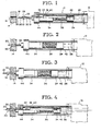
- a split mandrel hole expanding tool assembly generally designated as 10, is shown.
- the assembly 10 is mounted to puller gun 12.
- a workpiece 14 having a hole 16 to be coldworked is shown to the left of the assembly 10.
- Hole 16 is of such a diameter that pulling the split mandrel assembly 10 through it will cause coldworking.
- the tool assembly 10 contains a pilot assembly, generally designated as 18, which has a pilot 20, a rod 22, and a coupler 24.
- Pilot 20 has a small diameter portion 21 contained within the tool assembly 10, and a large diameter portion 23 extending outside of the tool assembly 10 prior to operation of the tool.
- the pilot 20 is threaded to the rod 22 which in turn is threaded to coupler 24.
- Coupler 24 is also threaded to the puller ram 26 of puller gun 12.
- the puller ram 26 of puller gun 12 transports left and right taking the pilot assembly 18 with it.
- the tool assembly 10 also contains a split mandrel assembly, generally designated as 28, which consists of split mandrel 30, housing 32, plug 34, and spring 36.
- Split mandrel 30 has a straight portion 31 and a flared portion 33 which is adapted to receive the pilot 20.
- Split mandrel 30 is threaded to housing 32, which in turn is threaded to plug 34.
- Spring 36 is located between coupler 24 of the pilot assembly 18, and plug 34 of the mandrel assembly 28. Spring 36 biases the mandrel assembly 28 to the left by pushing on coupler 24 which is secured to puller ram 26.
- the mandrel assembly 28 is extended due to this bias.
- Rod 22 has a shoulder 38 which contacts another should 40 of plug 34 of the mandrel assembly during retraction as best shown in Figure 5. This contact enables the pilot assembly 18 and mandrel assembly 28 to travel in unison to the right during retraction.
- Pilot assembly 18 and mandrel assembly 28 are contained partially within a barrel 42.
- Barrel 42 is fixedly attached to the puller gun 12 at one end and a cap 44 at the other end.
- the cap 44 retains the mandrel assembly 28 in barrel 42 and serves as a guide for coupler 24 of pilot assembly.
- the barrel 42 also 'contains spring 36 and guides it during operation.
- FIG. 6 an embodiment of split mandrel assembly 28 is shown wherein mandrel 30 has four segments designated as segments 46, 48, 50 and 52 with an offset split 54 between each segment.
- Figure 6 shows the offset 56 of offset split 54.
- the offset split 54 is accomplished by sweeping a split cut through an angle 58 ( Figure 7) about the longitudinal axis of mandrel 30.
- offset 56 of offset split 54 is located in a recessed diameter portion 60 of mandrel 30.
- Recessed diameter portion 60 of mandrel 30 is located between coldworking diameter portions 62 and 64 of mandrel 30.
- Locating offset 56 of offset split 54 in recessed diameter portion 60 of mandrel 30 between coldworking diameter portions 62 and 64 provides a means of pulling two coldworking diameter portions through one hole in succession with each portion having a different radial location for its split.
- the result of this configuration will be that the coldworked hole 16 will have a clean bore with no ridges or extraneous marks from offset 56 or offset split 54.
- the present invention may also be practiced without an offset split 54.
- the mandrel 30, in this case, would still be divided into four segments similar to segments 46, 48, 50 and 52 in Figure 7, but it would have no offset. As this type of mandrel is retracted through hole 16 in workpiece 14, small ridges would occur at four radial locations. These ridges could be reamed after coldworking.
Landscapes
- Engineering & Computer Science (AREA)
- Mechanical Engineering (AREA)
- Metal Extraction Processes (AREA)
- Forging (AREA)
Applications Claiming Priority (2)
| Application Number | Priority Date | Filing Date | Title |
|---|---|---|---|
| US45828283A | 1983-01-14 | 1983-01-14 | |
| US458282 | 1989-12-28 |
Publications (3)
| Publication Number | Publication Date |
|---|---|
| EP0114044A2 true EP0114044A2 (fr) | 1984-07-25 |
| EP0114044A3 EP0114044A3 (en) | 1984-10-10 |
| EP0114044B1 EP0114044B1 (fr) | 1987-11-19 |
Family
ID=23820143
Family Applications (1)
| Application Number | Title | Priority Date | Filing Date |
|---|---|---|---|
| EP19840100058 Expired EP0114044B1 (fr) | 1983-01-14 | 1984-01-04 | Procédé et dispositif pour le travail à froid d'alésages |
Country Status (2)
| Country | Link |
|---|---|
| EP (1) | EP0114044B1 (fr) |
| DE (1) | DE3467520D1 (fr) |
Cited By (1)
| Publication number | Priority date | Publication date | Assignee | Title |
|---|---|---|---|---|
| EP0140426A3 (en) * | 1983-09-30 | 1987-01-21 | West Coast Industries | Method and apparatus for hole coldworking |
Family Cites Families (3)
| Publication number | Priority date | Publication date | Assignee | Title |
|---|---|---|---|---|
| US2357123A (en) * | 1939-05-20 | 1944-08-29 | Babcock & Wilcox Co | Apparatus for producing pressure-tight tube and tube seat connections |
| US3358492A (en) * | 1965-09-08 | 1967-12-19 | Embassy Ind Inc | Mandrel construction |
| US3566662A (en) * | 1969-04-28 | 1971-03-02 | Boeing Co | Coldworking method and apparatus |
-
1984
- 1984-01-04 DE DE8484100058T patent/DE3467520D1/de not_active Expired
- 1984-01-04 EP EP19840100058 patent/EP0114044B1/fr not_active Expired
Cited By (1)
| Publication number | Priority date | Publication date | Assignee | Title |
|---|---|---|---|---|
| EP0140426A3 (en) * | 1983-09-30 | 1987-01-21 | West Coast Industries | Method and apparatus for hole coldworking |
Also Published As
| Publication number | Publication date |
|---|---|
| EP0114044B1 (fr) | 1987-11-19 |
| EP0114044A3 (en) | 1984-10-10 |
| DE3467520D1 (en) | 1987-12-23 |
Similar Documents
| Publication | Publication Date | Title |
|---|---|---|
| US4597282A (en) | Method and apparatus for coldworking holes | |
| US4665732A (en) | Method and apparatus for hole coldworking | |
| US5433100A (en) | Apparatus for split sleeve and tubular bushing cold expansion | |
| US4583388A (en) | Method and apparatus for hole coldworking | |
| EP0086344B1 (fr) | Méthode et appareil pour précontraindre un trou de fixation chanfreiné | |
| EP1743732B1 (fr) | Douilles à bride double et procédés d' assemblage | |
| EP0131648B1 (fr) | Procédé d'expansion à froid et de calibrage de trous pour éléments de fixation | |
| US4885829A (en) | Fatigue life enhancement of dovetail connector slots and noncircular openings | |
| US4423619A (en) | Apparatus and method for prestressing a countersunk fastener hole | |
| US4471643A (en) | Method and apparatus for prestressing fastener holes | |
| US4524600A (en) | Apparatus for prestressing fastener holes | |
| US4262518A (en) | Tube expander and method | |
| US4428220A (en) | Method and tool for the cold forging of internally profiled tubes | |
| US3983736A (en) | Helically wound mandrel assembly | |
| EP1115983B1 (fr) | Rivet aveugle et procede de fabrication correspondant | |
| US4869091A (en) | Tool for coldworking holes | |
| US4641407A (en) | Tooling for elastomeric swaging machine | |
| EP0114044A2 (fr) | Procédé et dispositif pour le travail à froid d'alésages | |
| US5129251A (en) | Manufacturing process for end fitting for eye joint | |
| US3411338A (en) | Tube flaring apparatus | |
| EP0234920B1 (fr) | Procédé pour remplacer les bouts de tuyaux d'un échangeur thermique | |
| WO2018024718A1 (fr) | Soudage par friction et cisaillement du bourrelet de soudure combinés | |
| US3475942A (en) | Apparatus for extruding tubular members from solid billets | |
| JP7577324B2 (ja) | 管内面の切削加工工具 | |
| US20030091680A1 (en) | Die assembly for forming a bead on a cylindrical tube |
Legal Events
| Date | Code | Title | Description |
|---|---|---|---|
| PUAI | Public reference made under article 153(3) epc to a published international application that has entered the european phase |
Free format text: ORIGINAL CODE: 0009012 |
|
| AK | Designated contracting states |
Designated state(s): DE FR GB IT NL SE |
|
| PUAL | Search report despatched |
Free format text: ORIGINAL CODE: 0009013 |
|
| AK | Designated contracting states |
Designated state(s): DE FR GB IT NL SE |
|
| 17P | Request for examination filed |
Effective date: 19850410 |
|
| ITF | It: translation for a ep patent filed | ||
| GRAA | (expected) grant |
Free format text: ORIGINAL CODE: 0009210 |
|
| AK | Designated contracting states |
Kind code of ref document: B1 Designated state(s): DE FR GB IT NL SE |
|
| REF | Corresponds to: |
Ref document number: 3467520 Country of ref document: DE Date of ref document: 19871223 |
|
| ET | Fr: translation filed | ||
| PLBE | No opposition filed within time limit |
Free format text: ORIGINAL CODE: 0009261 |
|
| STAA | Information on the status of an ep patent application or granted ep patent |
Free format text: STATUS: NO OPPOSITION FILED WITHIN TIME LIMIT |
|
| 26N | No opposition filed | ||
| ITTA | It: last paid annual fee | ||
| EAL | Se: european patent in force in sweden |
Ref document number: 84100058.1 |
|
| REG | Reference to a national code |
Ref country code: GB Ref legal event code: IF02 |
|
| PGFP | Annual fee paid to national office [announced via postgrant information from national office to epo] |
Ref country code: GB Payment date: 20021230 Year of fee payment: 20 |
|
| PGFP | Annual fee paid to national office [announced via postgrant information from national office to epo] |
Ref country code: FR Payment date: 20030130 Year of fee payment: 20 Ref country code: DE Payment date: 20030130 Year of fee payment: 20 |
|
| PGFP | Annual fee paid to national office [announced via postgrant information from national office to epo] |
Ref country code: SE Payment date: 20030131 Year of fee payment: 20 Ref country code: NL Payment date: 20030131 Year of fee payment: 20 |
|
| PG25 | Lapsed in a contracting state [announced via postgrant information from national office to epo] |
Ref country code: GB Free format text: LAPSE BECAUSE OF EXPIRATION OF PROTECTION Effective date: 20040103 |
|
| PG25 | Lapsed in a contracting state [announced via postgrant information from national office to epo] |
Ref country code: NL Free format text: LAPSE BECAUSE OF EXPIRATION OF PROTECTION Effective date: 20040104 |
|
| REG | Reference to a national code |
Ref country code: GB Ref legal event code: PE20 |
|
| NLV7 | Nl: ceased due to reaching the maximum lifetime of a patent |
Effective date: 20040104 |
|
| EUG | Se: european patent has lapsed |