EP0114070A2 - Brûleur ou tuyère d'injection pour l'utilisation dans un four métallurgique et sa disposition dans la paroi d'un tel four - Google Patents
Brûleur ou tuyère d'injection pour l'utilisation dans un four métallurgique et sa disposition dans la paroi d'un tel four Download PDFInfo
- Publication number
- EP0114070A2 EP0114070A2 EP84100338A EP84100338A EP0114070A2 EP 0114070 A2 EP0114070 A2 EP 0114070A2 EP 84100338 A EP84100338 A EP 84100338A EP 84100338 A EP84100338 A EP 84100338A EP 0114070 A2 EP0114070 A2 EP 0114070A2
- Authority
- EP
- European Patent Office
- Prior art keywords
- burner
- blowing nozzle
- nozzle according
- furnace
- vibration generator
- Prior art date
- Legal status (The legal status is an assumption and is not a legal conclusion. Google has not performed a legal analysis and makes no representation as to the accuracy of the status listed.)
- Ceased
Links
Images


Classifications
-
- F—MECHANICAL ENGINEERING; LIGHTING; HEATING; WEAPONS; BLASTING
- F23—COMBUSTION APPARATUS; COMBUSTION PROCESSES
- F23C—METHODS OR APPARATUS FOR COMBUSTION USING FLUID FUEL OR SOLID FUEL SUSPENDED IN A CARRIER GAS OR AIR
- F23C5/00—Disposition of burners with respect to the combustion chamber or to one another; Mounting of burners in combustion apparatus
- F23C5/02—Structural details of mounting
-
- C—CHEMISTRY; METALLURGY
- C21—METALLURGY OF IRON
- C21C—PROCESSING OF PIG-IRON, e.g. REFINING, MANUFACTURE OF WROUGHT-IRON OR STEEL; TREATMENT IN MOLTEN STATE OF FERROUS ALLOYS
- C21C5/00—Manufacture of carbon-steel, e.g. plain mild steel, medium carbon steel or cast steel or stainless steel
- C21C5/04—Manufacture of hearth-furnace steel, e.g. Siemens-Martin steel
-
- C—CHEMISTRY; METALLURGY
- C21—METALLURGY OF IRON
- C21C—PROCESSING OF PIG-IRON, e.g. REFINING, MANUFACTURE OF WROUGHT-IRON OR STEEL; TREATMENT IN MOLTEN STATE OF FERROUS ALLOYS
- C21C5/00—Manufacture of carbon-steel, e.g. plain mild steel, medium carbon steel or cast steel or stainless steel
- C21C5/52—Manufacture of steel in electric furnaces
- C21C5/5211—Manufacture of steel in electric furnaces in an alternating current [AC] electric arc furnace
- C21C5/5217—Manufacture of steel in electric furnaces in an alternating current [AC] electric arc furnace equipped with burners or devices for injecting gas, i.e. oxygen, or pulverulent materials into the furnace
-
- F—MECHANICAL ENGINEERING; LIGHTING; HEATING; WEAPONS; BLASTING
- F23—COMBUSTION APPARATUS; COMBUSTION PROCESSES
- F23D—BURNERS
- F23D11/00—Burners using a direct spraying action of liquid droplets or vaporised liquid into the combustion space
- F23D11/36—Details
-
- F—MECHANICAL ENGINEERING; LIGHTING; HEATING; WEAPONS; BLASTING
- F23—COMBUSTION APPARATUS; COMBUSTION PROCESSES
- F23D—BURNERS
- F23D14/00—Burners for combustion of a gas, e.g. of a gas stored under pressure as a liquid
- F23D14/32—Burners for combustion of a gas, e.g. of a gas stored under pressure as a liquid using a mixture of gaseous fuel and pure oxygen or oxygen-enriched air
-
- F—MECHANICAL ENGINEERING; LIGHTING; HEATING; WEAPONS; BLASTING
- F23—COMBUSTION APPARATUS; COMBUSTION PROCESSES
- F23D—BURNERS
- F23D14/00—Burners for combustion of a gas, e.g. of a gas stored under pressure as a liquid
- F23D14/46—Details
- F23D14/72—Safety devices, e.g. operative in case of failure of gas supply
- F23D14/78—Cooling burner parts
-
- F—MECHANICAL ENGINEERING; LIGHTING; HEATING; WEAPONS; BLASTING
- F27—FURNACES; KILNS; OVENS; RETORTS
- F27B—FURNACES, KILNS, OVENS OR RETORTS IN GENERAL; OPEN SINTERING OR LIKE APPARATUS
- F27B3/00—Hearth-type furnaces, e.g. of reverberatory type; Electric arc furnaces ; Tank furnaces
- F27B3/10—Details, accessories or equipment, e.g. dust-collectors, specially adapted for hearth-type furnaces
- F27B3/22—Arrangements of air or gas supply devices
-
- Y—GENERAL TAGGING OF NEW TECHNOLOGICAL DEVELOPMENTS; GENERAL TAGGING OF CROSS-SECTIONAL TECHNOLOGIES SPANNING OVER SEVERAL SECTIONS OF THE IPC; TECHNICAL SUBJECTS COVERED BY FORMER USPC CROSS-REFERENCE ART COLLECTIONS [XRACs] AND DIGESTS
- Y02—TECHNOLOGIES OR APPLICATIONS FOR MITIGATION OR ADAPTATION AGAINST CLIMATE CHANGE
- Y02P—CLIMATE CHANGE MITIGATION TECHNOLOGIES IN THE PRODUCTION OR PROCESSING OF GOODS
- Y02P10/00—Technologies related to metal processing
- Y02P10/20—Recycling
Definitions
- the invention relates to a burner or a blowing nozzle according to the preamble of claim 1. It also relates to an arrangement according to the preamble of claim 15.
- a burner of the type mentioned has become known, for example, from DE-AS 2013145.
- a pneumatically or hydraulically actuable reversing slide is provided, by means of which the supply of fuel and gases to the outlet opening of the burner can be controlled.
- the burners are pulled out or swung out of the furnace wall using mechanical devices during the breaks.
- the facilities are expensive and prone to failure. They require a high level of maintenance.
- the wall opening must be checked before the burner is reinserted and any slag adhered to it removed.
- the burner or the blowing nozzle In the burner or the blowing nozzle according to the invention, its outlet opening or the opening of the furnace wall in which the burner or the blowing nozzle is inserted can be closed by means of a displaceable body.
- a displaceable body As a result, metal and slag splashes can no longer get into the mouth of the burner or the blow nozzle and cause malfunctions during the breaks in operation, but rather they meet the body that closes the opening in question.
- This is formed in the area facing the furnace from scale-resistant material and, if necessary, coated with a material which is difficult to wet, such as graphite, in order to make it more difficult for metal and slag splashes to adhere.
- the body is also set to vibrate in this area, which immediately hurl off any splashes. Longitudinal vibrations are particularly suitable for this in the case of a piston-shaped body which can be displaced parallel to the burner or nozzle axis. However, transverse or mixed vibrations can also be used.
- the entire body can be vibrated, a mechanical vibration generator, an electromechanical vibration generator, a hydraulically or pneumatically operated vibration generator being suitable for generating the vibrations. It is essential, however, to set the surface of the body in vibration, which can hit the metal or slag splashes. It is therefore sufficient if this surface carries out these vibrations. This is particularly important if ultrasonic vibration generators are used in which the location of the vibration amplitudes within the body is influenced by the shape of the body. The vibration amplitude should be in the area of the impact surface of the splashes. It is therefore desirable to choose the shape and the mass distribution of the body so that an optimization of the vibration or sound field size is achieved, that is, the natural frequency of the body and the vibration modes within the body are matched to the frequency of the vibrator.
- the displaceable body and the vibration generator in terms of design and frequency, especially in the sound or ultrasonic wave range, so coordinated that sound or ultrasonic waves are emitted with such high energy from the surface of the body that slag is set into vibration in the space in front of the furnace interior in such a way that it decays or is thrown away .
- Removal of adhering slag particles or a slag layer in the area or in front of the nozzle mouth can, if necessary, also be combined with sound or ultrasound radiation by moving the actuating device for the displaceable body beyond the burner or nozzle mouth and during this pushing movement adhering metal or slag particles are mechanically removed or a slag layer is pierced.
- the body acts like a plunger or clearing device, through which the burner or the opening in the furnace wall can be freed of adhering foreign particles either automatically during each break in operation or also controlled during operation.
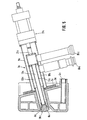
- a burner or a blowing nozzle 2 is arranged in the side wall 1 of a metallurgical furnace, such as a Siemens Martin furnace, a converter, a melter gasifier, an arc furnace, etc., above the melting level.
- the burner is located in a water cooler 3, which in turn is inserted in the refractory lining of the furnace. With 4 the water inlet and 5 the water return of the water cooling box 3 is designated.
- the water cooler 3 forms part of the wall 1 of the metallurgical furnace and has a wall opening 6 through which the fuel mixture or the gases of the burner or the blowing nozzle enter the interior of the furnace.
- the burner is attached to the water cooler 3 by means of a flange 7 in such a way that the outlet opening 8 of the burner directly adjoins the wall opening 6, and in the present case also has the same cross section as the wall opening 6.
- the burner 2 is constructed in a known manner from three concentric tubes 9, 10 and 11, whereby a central channel 12 and two ring channels 13 and 14 are formed.
- a fuel, such as fuel gas, can be fed to the inner ring channel 13 via a connection 15, and an oxygen-containing gas, such as oxygen, can be supplied to the outer ring channel 14 via a connection 16.
- the central channel 12 is usually also used for the supply of fuel gas or oxygen, and in the case of blowing nozzles, oxygen is generally introduced through the central channel 12 and a protective fluid through the ring channels 13 and 14.
- the burner 2 is assigned a body 18 which can be displaced by means of an actuating device 17.
- the body 18 is piston-shaped and in the central channel 12 of the burner 2, the cross section of which coincides approximately with the outlet opening 8 and with the wall opening 6, is axially displaceable.
- the body 18 can be pushed by means of the actuating device 17 from the retracted position shown in FIG. 1 into the position 24 shown in FIG. 2 with a solid line 24 or into the position 19 shown in FIG. 2 with a dashed line.
- the body 18 closes the wall opening 6 and thus prevents metal or slag splashes from becoming lodged within the wall opening 6.
- Metal or slag splashes already adhering to the wall opening 6 are removed when the piston-shaped body 18 is extended from the retracted position (FIG. 1) into the closed position (FIG. 2), since the outer cross section on the end face of the body 18 is almost the cross section of the Wall opening 6 corresponds.
- the body 18 does not have the task of interrupting the fuel or gas supply to the burner - this is done by valves (not shown) in the supply lines to the connections 15 and 16 - but rather the task of filling the wall opening 6 or against it Cover the interior of the furnace and remove any splashes already adhering to the wall opening when moving forward like a broaching tool.
- valves not shown
- the body 18 By pushing the body 18 further out into the furnace interior - position 19 of the body 18 shown in dashed lines in FIG. 2 - particles of slag or a layer of slag in front of the wall opening 6 can also be removed or pierced.
- the two ring channels 13 and 14 open into the central channel 12 in front of the outlet opening 8 of the burner 2.
- the different outlet openings of the ring channels 13 and 14 are brought together to form a single outlet opening 8 of the burner, which is closed in the closed position of the body 18 as well as the wall opening.
- Such training seems particularly useful when the burner mouth is directly exposed to the furnace atmosphere, i.e. there is no wall opening 6 of a water cooling box or the like connected to the outlet opening 8.
- the actuating device 17 is designed as a pneumatic linear actuator that acts in two directions.
- a piston not shown, is displaceable within a pneumatic cylinder 20 and is connected to the body 18 by a piston rod 21.
- the pneumatic cylinder contains compressed air connections 22 and 23 which open into the pneumatic cylinder 20 on different sides of the piston. This allows the piston and thus the body 18 to move back and forth between the positions shown in FIGS. 1 and 2.
- the position 19 shown in dashed lines in FIG. 2 can be provided either alternatively or in addition to the position 24 shown with a solid line.
- the pneumatic cylinder 20 should be dimensioned so that the body 18 knock off adhering metal or slag splashes like a plunger when moving out of the retracted position into the closed position and break through a slag layer formed in front of the wall opening 6 when the body 18 is moved into position 19 can.
- the part of the body in question that is to say the surface exposed to the area of action of the metal or slag splashes in the closed position, is set in vibration by means of a vibration generator 25.
- the waveform and the frequency By choosing the waveform and the frequency, the inside of the furnace facing surface of the body 18 are largely or completely kept free of slag.
- the surface of the body 18 in question can also be made of a heat-resistant, scaling-resistant material or be coated with such a material.
- the surface is deliberately not cooled, so that it is heated to a high temperature by the furnace heat, because at a higher temperature the slag runs off more easily due to the lower viscosity or can be more easily thrown off by the oscillating surface of the body 18.
- Chromium-nickel steels, nickel alloys, ceramic materials or graphite are suitable as scale-resistant materials. It is also advantageous to coat the surface of the body 18 exposed to the area affected by metal and slag splashes with a material which is difficult to wet. Graphite is particularly suitable for this. If there is a risk of overheating of the body 18, it is advisable to cool it.
- the vibration generator 25 is formed in the embodiment of FIGS. 1 and 2 as a pneumatic vibration generator, which operates in the example with a frequency of 1 Hz and thereby sets the body 18 in axial vibrations with a stroke of 15 mm.
- the piston rod 21 is hollow.
- the central channel of this piston rod is connected to a connection 26 for the compressed air.
- a larger amount of slag may spill in front of the burner opening, that is to say in the present case, in front of the wall opening 6 during the burner pause.
- the opening can be closed by a bell-shaped slag layer.
- This slag layer can be destroyed and the opening cleared again.
- Another method is to excite the slag layer by sonic or ultrasonic vibration and to make it collapse. This can be achieved, for example, by the burner design according to FIG. 4.
- the burner designs according to FIGS. 3 and 4 differ from the burner designs according to the figures 1 and 2 by different training of the vibration generator.
- the hydraulic vibration generator 25 of the embodiment according to FIGS. 1 and 2 is replaced by an electromagnetic vibration generator 30.
- a coil 31 is fixed within the central channel 12 of the burner 2a, through which a connecting rod 32 is guided to the body 18.
- This connecting rod 32 has an armature 33 on the side of the coil 31 facing the actuating device 17.
- the armature 33 is connected to the piston rod 21a of the actuating device 17 via an elastic coupling 34. In the closed position of the body 18 shown in FIG.
- the armature 33 is located in the vicinity of the end face of the coil 31, so that it can be set into vibrations when the coil 31 is supplied with alternating current by magnetic attraction. These vibrations are transmitted to the body 18 as axial vibrations and are largely decoupled from the actuating device 17 by the elastic coupling 34.
- the elastic coupling 34 By means of a suitable shape and mass distribution of the parts to be set in vibration, it is possible to set them into a resonance state at the desired frequency. It is essential here that a maximum vibration occurs on the surface of the body 18 exposed to the furnace atmosphere. However, the body 18 can also be forced to vibrate outside of its resonance frequency.
- an electromagnetic vibration generator it is expedient to utilize the existing network frequency, ie to set the body '18 in vibration at a frequency of 60 or 120 Hz.
- an ultrasonic oscillator 40 is provided as the vibration generator.
- This can be a quartz oscillator, for example.
- This excites the body 18b to a longitudinal vibration.
- a ring bearing 41 is provided at the location of a vibration node.
- the shape and the mass distribution are chosen so that the surface of the Body 18b is a maximum vibration.
- This vibrating surface also acts as an ultrasound emitter.
- the radiated energy can excite a layer of slag in front of it and cause it to decay.
- the oscillator is decoupled from the actuating device 17 by an elastic coupling.
- a sliding ring is designated by which the position of the axially displaceable body 18b in connection with the ring bearing 41 is defined.
- the burner 2c is designed as a so-called trumpet burner, which is used when a broad, less deep area is to be heated.
- the burner is attached by means of a flange 7c to a water cooler 3c with a water inlet 4c which is again inserted into the side wall of a metallurgical furnace.
- the burner axis is inclined downward in this embodiment.
- the burner is also constructed here from three concentric tubes 9c, 10c and 11c, the outer tube 9c taking on the task here of supporting the actuating device 17c for the displaceable body 18c.
- a central channel 12c for supplying the fuel gas and an annular channel 13c for supplying the oxygen are formed by the concentric tubes 10c and 11c.
- connections 15c and 16c for the fuel gas and oxygen open into these channels.
- the body 18c axially displaceable within the burner, but together with this body 18c the concentric tubes 10c and 11c are axially displaceable.
- the body 18c which in the present case is designed to spread the gas flows, is screwed tightly onto the inner tube 11c and the inner tube 11c is in turn firmly connected to the middle tube 10c.
- These tubes are axially displaceable together with the body 18c and the tube connections 15c and 16c by means of the actuating rod 21c, specifically from the one in FIG Fig. 5 position shown to the right until the body 18c closes the wall opening 6c and thus protects the outlet openings 8c for the fuel gas and oxygen from slag splashes.
- This example is intended to show that versatile modifications are possible within the scope of the invention.
Landscapes
- Engineering & Computer Science (AREA)
- Chemical & Material Sciences (AREA)
- Mechanical Engineering (AREA)
- General Engineering & Computer Science (AREA)
- Combustion & Propulsion (AREA)
- Manufacturing & Machinery (AREA)
- Materials Engineering (AREA)
- Metallurgy (AREA)
- Organic Chemistry (AREA)
- Vertical, Hearth, Or Arc Furnaces (AREA)
- Furnace Charging Or Discharging (AREA)
Applications Claiming Priority (2)
| Application Number | Priority Date | Filing Date | Title |
|---|---|---|---|
| DE3301466A DE3301466C1 (de) | 1983-01-18 | 1983-01-18 | Brenner bzw. Blasduese fuer den Einsatz in einem metallurgischen Ofen und Anordnung in der Wand eines solchen Ofens |
| DE3301466 | 1983-01-18 |
Publications (2)
| Publication Number | Publication Date |
|---|---|
| EP0114070A2 true EP0114070A2 (fr) | 1984-07-25 |
| EP0114070A3 EP0114070A3 (fr) | 1984-09-05 |
Family
ID=6188528
Family Applications (1)
| Application Number | Title | Priority Date | Filing Date |
|---|---|---|---|
| EP84100338A Ceased EP0114070A3 (fr) | 1983-01-18 | 1984-01-13 | Brûleur ou tuyère d'injection pour l'utilisation dans un four métallurgique et sa disposition dans la paroi d'un tel four |
Country Status (3)
| Country | Link |
|---|---|
| US (1) | US4497475A (fr) |
| EP (1) | EP0114070A3 (fr) |
| DE (1) | DE3301466C1 (fr) |
Cited By (2)
| Publication number | Priority date | Publication date | Assignee | Title |
|---|---|---|---|---|
| EP0639750A1 (fr) * | 1993-07-30 | 1995-02-22 | Co-Steel Sheerness Plc | Dispositif de fixation de brûleur |
| EP0706008A1 (fr) * | 1994-10-03 | 1996-04-10 | KYC, Inc. | Dispositif de brûleur à utiliser dans un four de fusion de verre |
Families Citing this family (13)
| Publication number | Priority date | Publication date | Assignee | Title |
|---|---|---|---|---|
| US4989784A (en) * | 1989-06-13 | 1991-02-05 | Fairchild Dean S | Fertilizer applicator attachment |
| DE3934340C1 (fr) * | 1989-10-14 | 1991-03-07 | Voest-Alpine Industrieanlagenbau Ges.M.B.H., Linz, At | |
| IT1275176B (it) * | 1995-02-06 | 1997-07-30 | Elti Srl | Apparecchiatura per l'insufflazione di gas o di fluidi in genere e di particolati particolarmente per l'insufflazione di ossigeno in forni per la produzione di acciaio |
| DE19817590C1 (de) * | 1998-04-20 | 1999-03-18 | Technometal Ges Fuer Metalltec | Variabel einsetzbare Kombilanze |
| ITMI20021526A1 (it) * | 2002-07-11 | 2004-01-12 | Danieli Off Mecc | Iniettore per forni di fusione di materiale metallico |
| DE10355549A1 (de) * | 2003-11-27 | 2005-06-23 | Intracon Gmbh | Chargiergutvorwärmer |
| DE102006012005A1 (de) * | 2006-03-16 | 2007-09-20 | Sms Demag Ag | Schmelz-Aggregat, insbesondere Injektor, Blaslanze oder Brenner |
| EP3208538A1 (fr) * | 2016-02-22 | 2017-08-23 | 3B Fibreglass sprl | Unité de refroidissement pour oxy-combustible |
| US11300291B2 (en) | 2016-11-03 | 2022-04-12 | Berry Metal Company | Burner housing |
| EP3480543A3 (fr) * | 2017-11-03 | 2019-08-21 | Berry Metal Company | Boîtier de brûleur |
| US10955135B2 (en) | 2018-06-18 | 2021-03-23 | Systems Spray-Cooled, Inc. | Burner panel for a metallurgical furnace |
| JP7242308B2 (ja) * | 2019-01-11 | 2023-03-20 | 三菱重工業株式会社 | バーナ、バーナシステム、ガス化複合発電設備、及びバーナの移動方法 |
| US12215861B2 (en) | 2021-12-13 | 2025-02-04 | Owens-Brockway Glass Container Inc. | Heat pipe for submerged combustion burner |
Family Cites Families (8)
| Publication number | Priority date | Publication date | Assignee | Title |
|---|---|---|---|---|
| US1647052A (en) * | 1927-10-25 | Sotting apparatus | ||
| US1835838A (en) * | 1931-12-08 | Sotting appabattjs | ||
| US294684A (en) * | 1884-03-04 | Bessemer converter | ||
| US2244079A (en) * | 1940-11-04 | 1941-06-03 | Phillip C Hall | Punching device |
| DE1608393C3 (de) * | 1967-04-26 | 1975-12-04 | Norddeutsche Affinerie, 2000 Hamburg | Durchstoßvorrichtung für der Windzuführung dienende Düsen von metallurgischen Konvertern, Schachtöfen oder dgl |
| AT287756B (de) * | 1969-04-18 | 1971-02-10 | Voest Ag | Brennerlanze |
| DE2541086A1 (de) * | 1975-09-15 | 1977-03-17 | Toshin Steel Co | Verfahren und vorrichtung zur stahlerzeugung |
| DE2601727A1 (de) * | 1976-01-19 | 1977-07-21 | Guenter Bender | Schutzueberzug fuer extrem waermebeanspruchte werkstueckflaechen |
-
1983
- 1983-01-18 DE DE3301466A patent/DE3301466C1/de not_active Expired
- 1983-12-12 US US06/560,510 patent/US4497475A/en not_active Expired - Fee Related
-
1984
- 1984-01-13 EP EP84100338A patent/EP0114070A3/fr not_active Ceased
Cited By (3)
| Publication number | Priority date | Publication date | Assignee | Title |
|---|---|---|---|---|
| EP0639750A1 (fr) * | 1993-07-30 | 1995-02-22 | Co-Steel Sheerness Plc | Dispositif de fixation de brûleur |
| EP0706008A1 (fr) * | 1994-10-03 | 1996-04-10 | KYC, Inc. | Dispositif de brûleur à utiliser dans un four de fusion de verre |
| US5542841A (en) * | 1994-10-03 | 1996-08-06 | Kyc, Inc. | Burner apparatus for use in a glass furnace |
Also Published As
| Publication number | Publication date |
|---|---|
| US4497475A (en) | 1985-02-05 |
| EP0114070A3 (fr) | 1984-09-05 |
| DE3301466C1 (de) | 1984-04-12 |
Similar Documents
| Publication | Publication Date | Title |
|---|---|---|
| DE3301466C1 (de) | Brenner bzw. Blasduese fuer den Einsatz in einem metallurgischen Ofen und Anordnung in der Wand eines solchen Ofens | |
| EP0124023B1 (fr) | Procédé et installation d'atomisation de métaux liquides pour l'obtention de poudres fines | |
| DE3043830C3 (de) | Lichtbogen-Plasma-Beschichtungssystem | |
| DE69603673T2 (de) | Lichtbogenplasmabrenner mit Wassereinspritzung-Düsenanordnung | |
| DE112009000138B4 (de) | Laserbearbeitungsvorrichtung und Laserbearbeitungsverfahren | |
| DE2216981B1 (de) | Verfahren zum Betrieb eines Plasma spntzbrenners und dessen konstruktive Ausgestaltung | |
| DE10128565B4 (de) | Thermisches Plasmaspritzen mit auf einen Draht übertragenem Lichtbogen mit hoher Abscheidungsgeschwindigkeit und Vorrichtung | |
| DE19520616C2 (de) | Düse für eine Schutzgas-Lichtbogenschweißmaschine, Schutzgas-Lichtbogenschweißmaschine mit einer Düse und Brenner hierfür | |
| EP0761345A2 (fr) | Machine à couler sous pression à chambre chaude | |
| DE1551710C3 (de) | Zerstäuberdüse für flüssigen und staubförmigen Brennstoff | |
| DE4242645A1 (de) | Verfahren und Vorrichtung zur Herstellung von Metallkügelchen annähernd gleichen Durchmessers | |
| DE1964040A1 (de) | Einrichtung zum Mischen von mindestens zwei fluiden Medien,insbesondere zur Herstellung brennbarer Gemische fluider Medien | |
| DE69706925T2 (de) | Plasmabrenner ohne Hochfrequenzzündung, mit Vorrichtungen zur Luftkühlung der Elektroden | |
| DE2413633C2 (de) | Brenner | |
| DE2726078B2 (de) | Verfahren und Vorrichtung zum Entfernen von Schlacke o.dgl. von geschmolzenem Metall | |
| DE2641425A1 (de) | Vorrichtung zum reinigen einer turbine | |
| DE1294153B (de) | Verfahren zum Schneiden von Werkstuecken | |
| DE1918964B2 (de) | Verfahren und vorrichtung zum bohren von loechern mit flammstrahlen | |
| DE4404954C2 (de) | Strahlapparat mit rotierender Strahldüse | |
| EP0365803B1 (fr) | Dispositif pour la projection de matériau de réparation sur une brique perforée | |
| CH651766A5 (en) | Explosive-coating system | |
| EP0271580B1 (fr) | Procede de revetement par projection au chalumeau d'installations metallurgiques | |
| DE102011103487A1 (de) | Vorrichtung zum thermischen Beschichten | |
| AT128301B (de) | Verfahren zur Verhinderung des Abbrandes der äußeren Elektrode von konzentrisch angeordneten Elektroden. | |
| DE3321118A1 (de) | Brenner fuer schmelzoefen |
Legal Events
| Date | Code | Title | Description |
|---|---|---|---|
| PUAI | Public reference made under article 153(3) epc to a published international application that has entered the european phase |
Free format text: ORIGINAL CODE: 0009012 |
|
| PUAL | Search report despatched |
Free format text: ORIGINAL CODE: 0009013 |
|
| 17P | Request for examination filed |
Effective date: 19840113 |
|
| AK | Designated contracting states |
Designated state(s): AT BE CH DE FR GB IT LI LU NL SE |
|
| AK | Designated contracting states |
Designated state(s): AT BE CH DE FR GB IT LI LU NL SE |
|
| STAA | Information on the status of an ep patent application or granted ep patent |
Free format text: STATUS: THE APPLICATION HAS BEEN REFUSED |
|
| 18R | Application refused |
Effective date: 19860512 |
|
| RIN1 | Information on inventor provided before grant (corrected) |
Inventor name: WABERSICH, ERNST, DIPL.-ING. Inventor name: FUCHS, GERHARD |