EP0114179A2 - Gekapselte, mit einem Isoliergas gefüllte Mittelspannungs Schaltanlage - Google Patents
Gekapselte, mit einem Isoliergas gefüllte Mittelspannungs Schaltanlage Download PDFInfo
- Publication number
- EP0114179A2 EP0114179A2 EP83107100A EP83107100A EP0114179A2 EP 0114179 A2 EP0114179 A2 EP 0114179A2 EP 83107100 A EP83107100 A EP 83107100A EP 83107100 A EP83107100 A EP 83107100A EP 0114179 A2 EP0114179 A2 EP 0114179A2
- Authority
- EP
- European Patent Office
- Prior art keywords
- housing
- gas
- switchgear
- tight
- switch
- Prior art date
- Legal status (The legal status is an assumption and is not a legal conclusion. Google has not performed a legal analysis and makes no representation as to the accuracy of the status listed.)
- Granted
Links
Images

Classifications
-
- H—ELECTRICITY
- H02—GENERATION; CONVERSION OR DISTRIBUTION OF ELECTRIC POWER
- H02B—BOARDS, SUBSTATIONS OR SWITCHING ARRANGEMENTS FOR THE SUPPLY OR DISTRIBUTION OF ELECTRIC POWER
- H02B13/00—Arrangement of switchgear in which switches are enclosed in, or structurally associated with, a casing, e.g. cubicle
- H02B13/02—Arrangement of switchgear in which switches are enclosed in, or structurally associated with, a casing, e.g. cubicle with metal casing
- H02B13/035—Gas-insulated switchgear
-
- H—ELECTRICITY
- H01—ELECTRIC ELEMENTS
- H01H—ELECTRIC SWITCHES; RELAYS; SELECTORS; EMERGENCY PROTECTIVE DEVICES
- H01H31/00—Air-break switches for high tension without arc-extinguishing or arc-preventing means
- H01H31/003—Earthing switches
Definitions
- the invention relates to an encapsulated medium-voltage switchgear filled with an insulating gas according to the preamble of claim 1.
- the invention is therefore based on the object of improving this switchgear in such a way that a phase earthing is achieved from the incoming cable via the switchgear to the outgoing cable.
- the switchgear consists of a housing 1, which has a four-sided prismatic shape and is arranged in landscape format.
- the front wall 2 of the housing serves to receive plugs 29, 29 ', 29 ". These three plugs each belong to a switch panel, the housing provided being intended for three switch panels.
- the housing has a rear wall 3, which is a welded-in part
- the upper side 4 of the housing offers a possibility for accommodating an actuating device 20 for the switch disconnectors.
- the use of the plugs which are connected to cables 7, 7 ', 7 makess it necessary for the housing to be pulled out when the plugs are pulled must be arranged at a certain height.
- a support frame 23 is used, which is firmly connected to the housing.
- An attachment 30 is provided for the high-voltage fuses. This attachment can be closed by means of a pivotable cover 33.
- the inside of the housing itself is divided into three horizontal chambers 38, 39 and 40 lying one above the other, which are optionally gas-tightly insulated from one another.
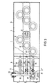
- FIG. 3 shows details of the interior of the housing, part of which shows the external view of the front wall 2.
- This is again a switchgear assembly with three switch panels 5.
- the individual switch panels are designed essentially the same, so that the description can be limited to one switch panel.
- Three switch disconnectors are provided, the switch blades 10, 10' and 10" of which move in the horizontal direction.
- the non-contacting switch blade ends 17, 17 'and 17 are connected to the switch shaft 19 via coupling rods 18.
- the switch shaft has the special feature that it is mounted on one side in the interior of the housing (21), while the other side has a gas-tight bushing 22 is guided to the outside.
- the ends of the switching knives which are designed as double knives, contact the busbars on both sides, a tension spring 24 being arranged between the knives.
- the knife ends are each equipped with a flap 25, which has the task of generating the flow required for arc quenching.
- the front is provided with a sight glass 37 at the level of the knife ends, in order to be able to check the condition of the separation distance.
- the entire housing is divided into three chambers 38, 39 and 40, so that each busbar phase is encapsulated.
- the control shaft is guided through the individual chambers, the bushings being gas-tight if necessary.
Landscapes
- Engineering & Computer Science (AREA)
- Power Engineering (AREA)
- Gas-Insulated Switchgears (AREA)
- Transformer Cooling (AREA)
Abstract
Description
- Die Erfindung bezieht sich auf eine gekapselte, mit einem Isoliergas gefüllte Mittelspannungs-Schaltanlage gemäß dem Oberbegriff des Anspruchs 1.
- Es ist bereits bekannt, alle wichtigen Teile einer Schaltanlage in einem einzigen gekapselten Gehäuse unterzubringen. Es hat sich nun herausgestellt, daß eine Unterbringung aller Teile in einem einzigen Raum dann unbefriedigend ist, wenn ein Querlichtbogen zwischen den Phasen auftritt.
- Der Erfindung liegt daher die Aufgabe zugrunde, diese Schaltanlage dahingehend zu verbessern, daß eine phasenweise Erdung vom eingehenden Kabel über die Schaltanlage bis zum ausgehenden Kabel erreicht wird.
- Diese Aufgabe wird erfindungsgemäß durch die im Kennzeichen des Anspruchs 1 angegebenen konstruktiven Maßnahmen gelöst.
- Die mit der Erfindung erzielten Vorteile bestehen darin, daß die Aufteilung der Schaltanlage in einzelne Kammern dazu führte auftretende Störfälle auf die jeweilige Phase zu beschränken.
- Sofern die Kammern voneinander unabhängige Gasvolumen besitzen, führt die Undichtigkeit einer Kammer nicht zum vollständigen Ausfall der Gesamtanlage.
- Ein Ausführungsbeispiel ist in einer Zeichnung dargestellt und wird im folgenden näher beschrieben. Es zeigen
- Fig. 1 eine Schaltanlage in Vorderansicht
- Fig. 2 in Seitenansicht
- Fig. 3 das Gehäuse dieser Schaltanlage in Vorderansicht, teilweise ohne Vorderwand.
- Nach den Fig. 1 und 2 besteht die Schaltanlage aus einem Gehäuse 1, das eine vierseitige prismatische Form aufweist und im Querformat angeordnet ist. Die Vorderwand 2 des Gehäuses dient der Aufnahme von Steckern 29, 29', 29". Diese drei Stekker gehören jeweils zu einem Schaltfeld, wobei das vorgesehene Gehäuse für drei Schaltfelder bestimmt ist. Das Gehäuse besitzt eine Rückwand 3, die als umlaufend eingeschweißtes Teil mit einer Sollbruchstelle ausgeführt ist. Die Oberseite 4 des Gehäuses bietet eine Aufnahmemöglichkeit für eine Betätigungsvorrichtung 20 für die Lasttrennschalter. Der Einsatz der Stecker, die mit Kabeln 7, 7', 7" verbunden sind, macht es beim Ziehen der Stecker erforderlich, daß das Gehäuse in einer bestimmten Höhe angeordnet sein muß. Hierzu dient ein Stützrahmen 23, der mit dem Gehäuse fest verbunden ist. Für die Hochspannungssicherungen ist ein Anbau 30 vorgesehen. Mittels eines schwenkbaren Deckels 33 kann dieser Anbau verschlossen werden. Das Gehäuse selbst ist im Inneren in drei übereinander liegende waagerechte Kammern 38, 39 und 40 unterteilt, die untereinander gegebenenfalls gasdicht isoliert sind.
- In der Fig. 3 sind Einzelheiten des Gehäuseinneren dargestellt, wobei einTeil die Außenansicht der Vorderwand 2 wiedergibt. Es handelt sich hier wiederum um eine Schaltanlage mit drei Schaltfeldern 5. Die einzelnen Schaltfelder sind im wesentlichen gleich gestaltet, so daß sich die Beschreibung auf ein Schaltfeld beschränken kann. An der Vorderwand des Gehäuses befinden sich je Schaltfeld drei diagonal angeordnete Durchführungen 6, 6' und 6". Es sind drei Lasttrennschalter vorgesehen, deren Schaltmesser 10, 10' und 10" sich in horizontaler Richtung bewegen. Die nicht kontaktierenden Schaltmesserenden 17, 17' und 17" sind über Koppelstangen 18 mit der Schaltwelle 19 verbunden. Die Schaltwelle weist dabei die Besonderheit auf, daß sie einseitig im Inneren des Gehäuses gelagert ist (21), während die andere Seite über eine gasdichte Durchführung 22 nach außen geführt ist.
- Die Enden der Schaltmesser, die als Doppelmesser ausgeführt sind, kontaktieren die Sammelschienen beidseitig, wobei zwischen den Messern jeweils eine Zugfeder 24 angeordnet ist. Außerdem sind die Messerenden jeweils mit einer Klappe 25 ausgestattet, die die Aufgabe hat, die notwendige Strömung für eine Lichtbogenlöschung zu erzeugen. Die Vorderseite ist in Höhe der Messerenden mit einem Schauglas 37 versehen, um den Zustand der Trennstrecke überprüfen zu können.
- Das gesamte Gehäuse ist in drei Kammern 38, 39 und 40 unterteilt, so daß jede Sammelschienenphase für sich gekapselt ist. Die Schaltwelle ist hierbei durch die einzelnen Kammern geführt, wobei die Durchführungen gegebenenfalls gasdicht sind.
Claims (2)
Priority Applications (1)
| Application Number | Priority Date | Filing Date | Title |
|---|---|---|---|
| AT83107100T ATE37968T1 (de) | 1982-12-27 | 1983-07-20 | Gekapselte, mit einem isoliergas gefuellte mittelspannungs schaltanlage. |
Applications Claiming Priority (2)
| Application Number | Priority Date | Filing Date | Title |
|---|---|---|---|
| DE19823248211 DE3248211A1 (de) | 1982-12-27 | 1982-12-27 | Gekapselte, mit einem isoliergas gefuellte mittelspannungs-schaltanlage |
| DE3248211 | 1982-12-27 |
Publications (4)
| Publication Number | Publication Date |
|---|---|
| EP0114179A2 true EP0114179A2 (de) | 1984-08-01 |
| EP0114179A3 EP0114179A3 (en) | 1986-05-28 |
| EP0114179B1 EP0114179B1 (de) | 1988-10-12 |
| EP0114179B2 EP0114179B2 (de) | 1992-05-06 |
Family
ID=6181900
Family Applications (1)
| Application Number | Title | Priority Date | Filing Date |
|---|---|---|---|
| EP83107100A Expired - Lifetime EP0114179B2 (de) | 1982-12-27 | 1983-07-20 | Gekapselte, mit einem Isoliergas gefüllte Mittelspannungs Schaltanlage |
Country Status (3)
| Country | Link |
|---|---|
| EP (1) | EP0114179B2 (de) |
| AT (1) | ATE37968T1 (de) |
| DE (1) | DE3248211A1 (de) |
Cited By (1)
| Publication number | Priority date | Publication date | Assignee | Title |
|---|---|---|---|---|
| EP0827246A3 (de) * | 1996-08-29 | 1999-08-11 | S&C ELECTRIC COMPANY | Schaltanlage |
Families Citing this family (2)
| Publication number | Priority date | Publication date | Assignee | Title |
|---|---|---|---|---|
| DE3715053A1 (de) * | 1987-05-06 | 1988-11-17 | Sachsenwerk Ag | Metallgekapselte, mit druckgas gefuellte, mehrphasige hochspannungsschaltanlage |
| DE19934350C1 (de) * | 1999-07-22 | 2000-09-28 | Felten & Guilleaume Ag | Metallgekapselte, druckgasisolierte Schaltanlage für Mittelspannungs-Netzstationen |
Family Cites Families (3)
| Publication number | Priority date | Publication date | Assignee | Title |
|---|---|---|---|---|
| DE1490578A1 (de) * | 1964-05-16 | 1969-07-10 | Sachsenwerk Licht & Kraft Ag | Blechgekapselte Betriebsmittel fuer Hochspannungschaltanlagen |
| DE2733777C2 (de) * | 1977-07-27 | 1986-08-14 | Fritz Driescher KG Spezialfabrik für Elektrizitätswerksbedarf GmbH & Co, 5144 Wegberg | Mittelspannungs-Kleinschaltanlage |
| DE3215234C2 (de) * | 1982-04-23 | 1986-10-30 | Felten & Guilleaume Energietechnik GmbH, 5000 Köln | Gekapselte, mit Isoliergas gefüllte Mittelspannungsschaltanlage |
-
1982
- 1982-12-27 DE DE19823248211 patent/DE3248211A1/de active Granted
-
1983
- 1983-07-20 AT AT83107100T patent/ATE37968T1/de not_active IP Right Cessation
- 1983-07-20 EP EP83107100A patent/EP0114179B2/de not_active Expired - Lifetime
Cited By (1)
| Publication number | Priority date | Publication date | Assignee | Title |
|---|---|---|---|---|
| EP0827246A3 (de) * | 1996-08-29 | 1999-08-11 | S&C ELECTRIC COMPANY | Schaltanlage |
Also Published As
| Publication number | Publication date |
|---|---|
| EP0114179A3 (en) | 1986-05-28 |
| DE3248211A1 (de) | 1984-07-05 |
| EP0114179B1 (de) | 1988-10-12 |
| DE3248211C2 (de) | 1987-05-27 |
| ATE37968T1 (de) | 1988-10-15 |
| EP0114179B2 (de) | 1992-05-06 |
Similar Documents
| Publication | Publication Date | Title |
|---|---|---|
| DE3715053C2 (de) | ||
| EP0688071B1 (de) | Metallgekapselte gasisolierte Schaltanlage | |
| DE102010013877B4 (de) | Elektrischer Leistungsschalter und Schaltfeld mit Leistungsschalter | |
| EP0093225B1 (de) | Gekapselte, mit einem Isoliergas gefüllte Mittelspannungsschaltanlage | |
| DE3915948A1 (de) | Lastschaltanlage mit einem dreistellungsschalter | |
| EP0005208A1 (de) | Elektrisches Schaltfeld | |
| DE3927835A1 (de) | Gekapselte mittelspannungsschaltanlage | |
| EP0678955B1 (de) | Metallgekapselte gasisolierte Schaltanlage | |
| DE2438951C2 (de) | Blechgekapselte, vorgefertigte Mittelspannungs-Schaltanlage mit mehreren luftisolierten Zellen kleiner Abmessungen | |
| EP0452639B1 (de) | Metallgekapselte, druckgasisolierte Schaltanlage für kompakte Netzstationen im Mittelspannungsbereich | |
| DE2823056C2 (de) | ||
| EP0114179B2 (de) | Gekapselte, mit einem Isoliergas gefüllte Mittelspannungs Schaltanlage | |
| EP0796502A1 (de) | Metallgekapselte schaltanlage mit einem vakuumschaltgerät | |
| DE9420193U1 (de) | Gasisolierte Leistungsschalter-Anlage | |
| WO2004109882A2 (de) | Gasisoliertes sammelschienenbauteil mit freiluftdurchführung | |
| AT5324U1 (de) | Gekapselte elektrische schaltzelle für hochspannung | |
| DE1665260B2 (de) | Metallumschlossene, phasenweise gekapselte Hochspannungsschaltanlage | |
| DE1540176A1 (de) | Gekapselte Umschalteinrichtung fuer mittlere oder hohe Spannung | |
| EP0454961B1 (de) | Gasisolierte Schaltanlage für den Einsatz in Netzverteilerstationen | |
| DE29700930U1 (de) | Hochspannungsschaltanlage mit einem Dead-Tank-Schalter | |
| DE1810404A1 (de) | Metallgekapselte Hochspannungs-Schaltanlage | |
| AT228323B (de) | Vorgefertigte durch Steckverbindungen schaltbare elektrische Schaltzelle | |
| DE2325397A1 (de) | Geschottete elektrische schaltanlage | |
| DE1590195A1 (de) | Innenraumschaltanlage mit Doppel-bzw.Mehrfachsammelschienen | |
| DE1224813B (de) | Steckbare elektrische Geraeteteile |
Legal Events
| Date | Code | Title | Description |
|---|---|---|---|
| PUAI | Public reference made under article 153(3) epc to a published international application that has entered the european phase |
Free format text: ORIGINAL CODE: 0009012 |
|
| AK | Designated contracting states |
Designated state(s): AT BE CH FR GB IT LI NL SE |
|
| PUAL | Search report despatched |
Free format text: ORIGINAL CODE: 0009013 |
|
| AK | Designated contracting states |
Kind code of ref document: A3 Designated state(s): AT BE CH FR GB IT LI NL SE |
|
| 17P | Request for examination filed |
Effective date: 19860718 |
|
| RAP1 | Party data changed (applicant data changed or rights of an application transferred) |
Owner name: FELTEN & GUILLEAUME ENERGIETECHNIK AG |
|
| 17Q | First examination report despatched |
Effective date: 19870119 |
|
| GRAA | (expected) grant |
Free format text: ORIGINAL CODE: 0009210 |
|
| AK | Designated contracting states |
Kind code of ref document: B1 Designated state(s): AT BE CH FR GB IT LI NL SE |
|
| REF | Corresponds to: |
Ref document number: 37968 Country of ref document: AT Date of ref document: 19881015 Kind code of ref document: T |
|
| ITF | It: translation for a ep patent filed | ||
| GBT | Gb: translation of ep patent filed (gb section 77(6)(a)/1977) | ||
| ET | Fr: translation filed | ||
| PLBI | Opposition filed |
Free format text: ORIGINAL CODE: 0009260 |
|
| 26 | Opposition filed |
Opponent name: SACHSENWERK AKTIENGESELLSCHAFT Effective date: 19890707 |
|
| NLR1 | Nl: opposition has been filed with the epo |
Opponent name: SACHSENWERK AG |
|
| ITTA | It: last paid annual fee | ||
| PUAH | Patent maintained in amended form |
Free format text: ORIGINAL CODE: 0009272 |
|
| STAA | Information on the status of an ep patent application or granted ep patent |
Free format text: STATUS: PATENT MAINTAINED AS AMENDED |
|
| 27A | Patent maintained in amended form |
Effective date: 19920506 |
|
| AK | Designated contracting states |
Kind code of ref document: B2 Designated state(s): AT BE CH FR GB IT LI NL SE |
|
| REG | Reference to a national code |
Ref country code: CH Ref legal event code: AEN |
|
| GBTA | Gb: translation of amended ep patent filed (gb section 77(6)(b)/1977) | ||
| NLR2 | Nl: decision of opposition | ||
| ITF | It: translation for a ep patent filed | ||
| NLR3 | Nl: receipt of modified translations in the netherlands language after an opposition procedure | ||
| ET3 | Fr: translation filed ** decision concerning opposition | ||
| EAL | Se: european patent in force in sweden |
Ref document number: 83107100.6 |
|
| PGFP | Annual fee paid to national office [announced via postgrant information from national office to epo] |
Ref country code: NL Payment date: 19950731 Year of fee payment: 13 Ref country code: FR Payment date: 19950731 Year of fee payment: 13 |
|
| PGFP | Annual fee paid to national office [announced via postgrant information from national office to epo] |
Ref country code: SE Payment date: 19960513 Year of fee payment: 14 |
|
| PGFP | Annual fee paid to national office [announced via postgrant information from national office to epo] |
Ref country code: GB Payment date: 19960711 Year of fee payment: 14 |
|
| PGFP | Annual fee paid to national office [announced via postgrant information from national office to epo] |
Ref country code: BE Payment date: 19960719 Year of fee payment: 14 Ref country code: AT Payment date: 19960719 Year of fee payment: 14 |
|
| PGFP | Annual fee paid to national office [announced via postgrant information from national office to epo] |
Ref country code: CH Payment date: 19960722 Year of fee payment: 14 |
|
| PG25 | Lapsed in a contracting state [announced via postgrant information from national office to epo] |
Ref country code: NL Effective date: 19970201 |
|
| PG25 | Lapsed in a contracting state [announced via postgrant information from national office to epo] |
Ref country code: FR Effective date: 19970328 |
|
| NLV4 | Nl: lapsed or anulled due to non-payment of the annual fee |
Effective date: 19970201 |
|
| REG | Reference to a national code |
Ref country code: FR Ref legal event code: ST |
|
| PG25 | Lapsed in a contracting state [announced via postgrant information from national office to epo] |
Ref country code: GB Free format text: LAPSE BECAUSE OF NON-PAYMENT OF DUE FEES Effective date: 19970720 Ref country code: AT Free format text: LAPSE BECAUSE OF NON-PAYMENT OF DUE FEES Effective date: 19970720 |
|
| PG25 | Lapsed in a contracting state [announced via postgrant information from national office to epo] |
Ref country code: SE Effective date: 19970721 |
|
| PG25 | Lapsed in a contracting state [announced via postgrant information from national office to epo] |
Ref country code: LI Free format text: LAPSE BECAUSE OF NON-PAYMENT OF DUE FEES Effective date: 19970731 Ref country code: CH Free format text: LAPSE BECAUSE OF NON-PAYMENT OF DUE FEES Effective date: 19970731 Ref country code: BE Free format text: LAPSE BECAUSE OF NON-PAYMENT OF DUE FEES Effective date: 19970731 |
|
| BERE | Be: lapsed |
Owner name: FELTEN & GUILLEAUME ENERGIETECHNIK A.G. Effective date: 19970731 |
|
| GBPC | Gb: european patent ceased through non-payment of renewal fee |
Effective date: 19970720 |
|
| REG | Reference to a national code |
Ref country code: CH Ref legal event code: PL |
|
| EUG | Se: european patent has lapsed |
Ref document number: 83107100.6 |