EP0114266A2 - Dispositif de signalisation - Google Patents
Dispositif de signalisation Download PDFInfo
- Publication number
- EP0114266A2 EP0114266A2 EP83112140A EP83112140A EP0114266A2 EP 0114266 A2 EP0114266 A2 EP 0114266A2 EP 83112140 A EP83112140 A EP 83112140A EP 83112140 A EP83112140 A EP 83112140A EP 0114266 A2 EP0114266 A2 EP 0114266A2
- Authority
- EP
- European Patent Office
- Prior art keywords
- signal device
- handle
- trigger
- magazine
- signal
- Prior art date
- Legal status (The legal status is an assumption and is not a legal conclusion. Google has not performed a legal analysis and makes no representation as to the accuracy of the status listed.)
- Granted
Links
Images



Classifications
-
- F—MECHANICAL ENGINEERING; LIGHTING; HEATING; WEAPONS; BLASTING
- F41—WEAPONS
- F41A—FUNCTIONAL FEATURES OR DETAILS COMMON TO BOTH SMALLARMS AND ORDNANCE, e.g. CANNONS; MOUNTINGS FOR SMALLARMS OR ORDNANCE
- F41A19/00—Firing or trigger mechanisms; Cocking mechanisms
- F41A19/06—Mechanical firing mechanisms, e.g. counterrecoil firing, recoil actuated firing mechanisms
- F41A19/42—Mechanical firing mechanisms, e.g. counterrecoil firing, recoil actuated firing mechanisms having at least one hammer
- F41A19/52—Cocking or firing mechanisms for other types of guns, e.g. fixed breech-block types, revolvers
- F41A19/53—Double-action mechanisms, i.e. the cocking being effected during the first part of the trigger pull movement
-
- F—MECHANICAL ENGINEERING; LIGHTING; HEATING; WEAPONS; BLASTING
- F41—WEAPONS
- F41A—FUNCTIONAL FEATURES OR DETAILS COMMON TO BOTH SMALLARMS AND ORDNANCE, e.g. CANNONS; MOUNTINGS FOR SMALLARMS OR ORDNANCE
- F41A17/00—Safety arrangements, e.g. safeties
- F41A17/74—Hammer safeties, i.e. means for preventing the hammer from hitting the cartridge or the firing pin
-
- F—MECHANICAL ENGINEERING; LIGHTING; HEATING; WEAPONS; BLASTING
- F41—WEAPONS
- F41C—SMALLARMS, e.g. PISTOLS, RIFLES; ACCESSORIES THEREFOR
- F41C3/00—Pistols, e.g. revolvers
- F41C3/02—Signal pistols, e.g. Very pistols
Definitions
- the invention relates to a signal device for firing signal cartridges.
- the weapons construction design also provides for a horizontal e re ch in natural hand position - before th-plane Committee direction.
- the mouth of the signal gun In order to achieve a large angle favoring the detection of the emergency signal when firing, the mouth of the signal gun must first be moved in the direction of the vertical. This presupposes a hand position that deviates from the natural hand position, which in an emergency situation places additional considerations on those in need.
- the invention has for its object to provide a signal device for firing signal cartridges, which can only be operated with one hand, which allows a natural hand gesture to issue the emergency signal in the vertical direction and which is also characterized by a simple and safe construction, so that it can also be used in the leisure sector due to its value for money.
- the signal device is intended to enable one-handed operation in a natural hand position by a person who has got into an emergency situation, the emitting of the emergency signal d. H. the rejection of a light or smoke charge should possibly be connected vertically upward in connection with a sound signal.
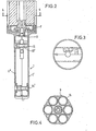
- the handle 1 comprises a handle 1, which is designed as the trigger mechanism and the means for transporting the magazine 6 enveloping hollow body, the longitudinal axis of which is perpendicular when held naturally.
- the magazine 6, the structure of which will be discussed in more detail later, can be plugged onto the handle 1 and connected to it in such a way that the reject direction corresponds to the direction of the longitudinal axis of the handle 1.
- the dimensions of the handle 1 are chosen so that it can be comfortably spanned by one hand.
- the handle 1 essentially comprises two handle shells 1 ', 1 ", which can be connected to one another by means of fillister screws 13, 13' and, after being joined together, enclose a substantially cuboid space between them.
- handle shells 1 ' , 1" are preferably made of plastic
- threaded inserts made of metal or of a particularly high-quality plastic are arranged in at least one handle shell 1 ', 1 ".
- Part of the outer wall of the hollow body forming the handle 1 in the region of its narrow side is formed by the actuating surface 31 of the trigger lever 3 In this way, the actuating surface 31 can be actuated in a normal manner, even with clammy fingers or with a hand clad in gloves, to activate the signaling device if necessary.
- the firing pin (FIG. 1, FIG. 9) essentially consists of two cylindrical sections 90, 91 of different diameters, each of which adjoins one side of a collar 92.
- the somewhat rounded tip of the longer cylindrical section 90 with a smaller diameter comes into operative connection with the primer of the signal cartridge to be fired, while the end face of the shorter cylindrical section 91, which is equipped with a larger diameter, is acted upon by the stop surface of the hammer 4.
- the cylindrical lateral surfaces of the sections 90, 91 of the firing pin 10 serve to mount the firing pin in the handle 1.
- a compression spring 12 arranged coaxially with the firing pin 10 forces the firing pin 10 into a rest position, in which the collar 92 of the firing pin 10 on an inner wall of the handle 1 rests.
- the firing process proceeds as follows: The fingers of the hand enclosing the handle 1 move the trigger lever 3, which is rotatably mounted about the axis 13, in the direction of the longitudinal axis of the signaling device, as a result of which the compression spring 11 mounted on the pin 30, 40 is tensioned.
- the end piece of the claw 9, which is firmly connected to the trigger lever 3, lies in front of a step 42 arranged in the outer circumferential surface of the hammer 4 and gives the hammer 4, which is rotatably mounted about the axis 13 ', a rotational movement in the counterclockwise direction.
- the hammer 4 lifts from the blow surface of the firing pin 10 and compresses the compression spring 11 further.
- FIG. 15 shows a side view of the handle in a perspective view.
- the securing device prevents the hammer 4 from hitting the firing pin 10.
- the securing device consists of a shaft 150 which is rotatably mounted in both halves of the handle 1 and which is firmly connected to a securing lever 151 designed as a crank mechanism.
- the locking lever 151 is rotatably arranged within a recess arranged in the outer wall of the grip sleeve within a circular sector between a locking locking position S on the one hand and a firing position F on the other hand.
- the safety lever 151 is actuated with the thumb of the hand enclosing the handle 1.
- the essentially cylindrical locking shaft 151 is part of its longitudinal extension on opposite parts of the outer surface. flat, so that the area 152 of the securing shaft 150 is delimited by two parallel flat surfaces on the one hand and two opposite cylinder jacket surfaces on the other. With the area 152, the securing shaft L50 extends through a slot 153 arranged in the hammer 4, the width of which is smaller than the largest diameter of the shaft 150 in its area 152. In securing S, the flat boundary surfaces of the area 152 of the securing shaft 150 are in a vertical position of the handle 1 in a horizontal plane, so that the slot 153 of the hammer 4 "sees" the largest diameter of the locking shaft 150 in its area 152.
- a holder 154 which is only indicated schematically in FIG. 15, comprises two projecting lugs 155 which engage in the form of adapted recesses or depressions 156 of the handle. This engagement is only possible when the safety lever 151 is in the S position. In this way, unintentional firing is excluded if the signaling device is engaged in the holder 154 in the ready state.
- the trigger 3 not only serves to initiate the firing process, but also has a dual function for transporting the signal cartridges held in the rotatably arranged magazine 6. In order to accomplish this transport, the approximately linear plane running in a plane containing the longitudinal axis of the signal device must be used
- the free end piece of the trigger 3 comprises a pot-like recess 33 (FIG. 1) into which a pin 70 protruding from the plane of a driving ring 7 engages. (Fig. 7, Fig. 8). Since the pin 70 is arranged eccentrically, the force that acts tangentially on the trigger lever 3 via the movement of the trigger lever 3 when the trigger lever 3 is pressed in and released leads to a rotational movement of the driving ring 7 with a maximum predetermined angle of rotation, which only includes a certain circle segment.
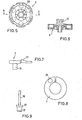
- the driver ring 7 is shown in FIGS. 7 and 8 on an enlarged scale. 7 shows a side view and FIG.
- FIG. 8 shows a top view of the outer surface of the driving ring 7, from which the pin 70 protrudes.
- the outer surface of the driver ring 7 facing away from the driver 70 carries a step 71 which in turn engages in roof-like projections 50 of the transport disk 5 (FIG. 5) arranged on a circular circumference.
- FIG. 6 shows a section through the transport disk 5 shown in FIG. 5 along the line 6-6.
- a slotted pin 51 is arranged for receiving the plug-in magazines for the signal cartridges, which guarantees a reliable releasable fastening of the magazine due to its radially outward spring force.
- the signal cartridges are transported further as follows: An initial state is assumed in which an ignitable signal cartridge is located above the Firing pin 10 is located. This corresponds to the standby status of the signal device. Pressing the trigger 3 leads to the firing process already described in detail above. Simultaneously with the tilting movement of the trigger lever 3 articulated on one side, however, the driving ring 7 is rotated because the pin 70 of the driving ring 7 engages in the cup-shaped recess 33 at the free end of the trigger lever 3. During this rotational movement, the edge of the step 71 of the driving ring 7 slides on the roof-shaped inclined surface - one of the projections 50 along the transport disc 5, which remains at rest and does not participate in the rotational movement of the driving ring 7.
- the stage 71 finally engages - after overcoming the inclined surface behind a projection 50 and then, when the trigger lever 3 withdraws into its rest position, rotates the transport disk 5 by the predetermined angular value, so that a new ignitable signal cartridge is located above the firing pin 10 and the signal device is ready again.
- FIGS. 10, 11 and 12 each show a top view of the end faces of the magazine, while FIG. 11 shows a longitudinal section through the magazine along the line 11-11 according to FIG. 10.
- the end faces are star-shaped, since radially projecting projections are provided starting from a centrally arranged column, between which the signal cartridges can be clamped.
- FIG. 4 shows a cross section through a magazine filled with signal cartridges along the line 4-4 of FIG. 2 and in this way illustrates the appearance of the magazine equipped with signal cartridges.
- the magazine construction described above is particularly advantageous in terms of saving weight.
- the signaling device which is in the ready state with an attached magazine, can be fixed in a suitable holder, which is not described separately here, arranged in a stationary manner, but can be kept within reach at all times.
- This storage option is particularly suitable for vehicles of all types, where there is enough space available.
- the signal device can also be used to advantage in the sports or leisure sector if a fixed attachment is not an option and the signal device is to be carried on a man. Mountain hikers and / or surfers are particularly important.
- the signaling device which is in the ready state with an attached magazine, is attached to luggage, to clothing or directly to the limbs with a suitable harness.
- This type of fastening is particularly favored by a packaging form explained with reference to FIGS. 13 and 14, which also greatly facilitates the presentation and storage of the signal device.
- Ver - packaging form is, or as a blister pack. basically known as shrink film packaging in the packaging sector. It consists of a supporting base 140, for which cardboard, plastic or the like can be used. On this supporting pad 140, the Transparent film 141 covered signal device arranged. Recesses are provided in the supporting base 140, through which harnesses suitable for transporting and holding the signal device can be pulled.
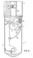
- Fig. 16 shows in longitudinal section a further embodiment of the invention, which is also characterized by a special securing device.
- This safety device prevents actuation of the signal device and thus firing of a signal cartridge when the reject opening of the magazine is directed towards the person himself.
- This is achieved in a simple manner in that the claw 9 is fastened about an axis 9 'to the free end piece of the rotatable trigger lever 3 / and additionally carries a weighting pin 160.
- the weighting pin is preferably made of metal, e.g. B. iron.
- the hammer 4 When the trigger 3 was pressed, the hammer 4 would accordingly be rotated and the firing process - as already described above - take place. If, on the other hand, the signal device is inclined in such a way that in particular the reject opening of the magazine) 6 points towards the person himself, the claw 9 tilts about the axis 9 'due to the gravity acting on the eccentrically arranged weighting pin 160 such that the claw 9 is off the hammer 4 takes off and is no longer in engagement with its level 42. A pressure on the trigger 3 would therefore no longer lead to a rotary movement of the hammer and would therefore not initiate a firing process.
- the rotatably arranged claw 9 also simplifies the device for securing the signaling device 1.
- a safety switch 163 is now provided for this purpose, which, parallel to the longitudinal axis of the signaling device, between two positions, namely a securing position 'S "and a firing position” F ".
- the safety switch 163 carries a radially projecting shoulder 162 which lifts the claw 9 from the step 42 of the hammer 4 in the safety position" S “and thus a rotation of the trigger 3 when the trigger is actuated Hammers prevented.
- the safety switch 163 In the firing position "F", the safety switch 163 is pushed down so that the attachment 162 no longer comes into contact with the claw 9.
- the claw 9 can therefore reach behind the step 42 of the hammer 4 and, when the trigger lever 3 is pressed in, turn the hammer to trigger the firing process.
- the signal device shown in FIG. 16 is still considerably simplified in that all devices for the automatic rotation of the magazine 6 have been omitted.
- a centrally arranged fixed magazine holder 164 is provided, which comprises a transverse bore in which at least one ball 166 loaded by a compression spring 165 is mounted, which exerts a force in the radial direction on an attached magazine 6.
- the attached magazine 6 is held in its respective position.
- a new cartridge 18 is simply brought into the firing position by rotating the magazine 6 into a new position with the thumb of the hand holding the signal device, for which purpose the holding force of the compression spring 165 must of course be overcome.
- the inner wall of the magazine 6 placed on the magazine holder 164 opposite the ball 166 is preferably designed as a hexagonal surface.
- the magazine 6 comprises six signal cartridges, it can be rotated relatively easily by 60 ° to the next rest point.
- the ball 166 also secures the magazine 6 on the magazine holder 164, in which it rests on a step 167 in the inner wall of the magazine 6.
- the hammer 4 is not loaded by a compression spring, but by a leaf spring 167 which is supported on the trigger lever 3.
Landscapes
- Engineering & Computer Science (AREA)
- General Engineering & Computer Science (AREA)
- Portable Nailing Machines And Staplers (AREA)
- Radar Systems Or Details Thereof (AREA)
- Input Circuits Of Receivers And Coupling Of Receivers And Audio Equipment (AREA)
- Catching Or Destruction (AREA)
- Percussive Tools And Related Accessories (AREA)
- Maintenance And Management Of Digital Transmission (AREA)
- Power Steering Mechanism (AREA)
- Seal Device For Vehicle (AREA)
Priority Applications (1)
| Application Number | Priority Date | Filing Date | Title |
|---|---|---|---|
| AT83112140T ATE33897T1 (de) | 1983-01-20 | 1983-12-02 | Signalgeraet. |
Applications Claiming Priority (2)
| Application Number | Priority Date | Filing Date | Title |
|---|---|---|---|
| DE19833301683 DE3301683A1 (de) | 1983-01-20 | 1983-01-20 | Signalgeraet |
| DE3301683 | 1983-01-20 |
Publications (3)
| Publication Number | Publication Date |
|---|---|
| EP0114266A2 true EP0114266A2 (fr) | 1984-08-01 |
| EP0114266A3 EP0114266A3 (en) | 1986-09-03 |
| EP0114266B1 EP0114266B1 (fr) | 1988-04-27 |
Family
ID=6188667
Family Applications (1)
| Application Number | Title | Priority Date | Filing Date |
|---|---|---|---|
| EP83112140A Expired EP0114266B1 (fr) | 1983-01-20 | 1983-12-02 | Dispositif de signalisation |
Country Status (18)
| Country | Link |
|---|---|
| US (1) | US4592159A (fr) |
| EP (1) | EP0114266B1 (fr) |
| JP (1) | JPS59189297A (fr) |
| KR (1) | KR880000161B1 (fr) |
| AR (1) | AR231771A1 (fr) |
| AT (1) | ATE33897T1 (fr) |
| AU (1) | AU562378B2 (fr) |
| CA (1) | CA1221567A (fr) |
| DE (2) | DE3301683A1 (fr) |
| DK (1) | DK159895C (fr) |
| ES (1) | ES8406713A1 (fr) |
| FI (1) | FI77729C (fr) |
| GR (1) | GR81686B (fr) |
| IL (1) | IL70679A (fr) |
| MX (1) | MX157761A (fr) |
| NO (1) | NO166464C (fr) |
| NZ (1) | NZ206888A (fr) |
| ZA (1) | ZA84286B (fr) |
Families Citing this family (7)
| Publication number | Priority date | Publication date | Assignee | Title |
|---|---|---|---|---|
| DE9000943U1 (de) * | 1990-01-29 | 1990-04-12 | Cuno Melcher KG ME-Sportwaffen, 5650 Solingen | Signalgeber für Leuchtmunition |
| US5924229A (en) * | 1998-01-27 | 1999-07-20 | Skyblazer, Inc. | Flare launcher |
| US6415538B1 (en) | 2000-01-17 | 2002-07-09 | William F. Brice | Breech locking safety bracket for flare launchers |
| US6502343B2 (en) * | 2001-03-30 | 2003-01-07 | Joung Young Cheng | Emergency rescue device |
| CA2546252A1 (fr) * | 2005-03-08 | 2006-09-08 | Eugen Nicolae | Distributeur de fusees eclairantes |
| US8047307B2 (en) * | 2008-12-19 | 2011-11-01 | Baker Hughes Incorporated | Hybrid drill bit with secondary backup cutters positioned with high side rake angles |
| DE202011004434U1 (de) | 2011-03-25 | 2011-06-01 | Schacht, Henning, 22926 | Vorrichtung zum Abgeben eines Notsignals |
Family Cites Families (12)
| Publication number | Priority date | Publication date | Assignee | Title |
|---|---|---|---|---|
| US1376165A (en) * | 1920-01-26 | 1921-04-26 | Waldo E Rosebush | Firearm |
| CH271401A (fr) * | 1949-02-22 | 1950-10-31 | Martinez De Lecea Y Uriarte Do | Appareil pour le lancement de fusées de signalisation et autres. |
| BE551448A (fr) * | 1956-09-04 | |||
| US3097559A (en) * | 1958-07-28 | 1963-07-16 | Aerpat Ag | Clevis pin with spring urged detents and means to limit spring movement |
| FR1297219A (fr) * | 1961-05-16 | 1962-06-29 | Chimie Et Propulsion | Pistolet pour le lancement d'un signal |
| DE1174211B (de) * | 1962-01-12 | 1964-07-16 | Elke Eberwein | Signalschiessgeraet |
| US3270455A (en) * | 1964-12-28 | 1966-09-06 | Ronald B Smernoff | Semi-automatic repeating flare pistol |
| DE2108010A1 (de) * | 1971-02-19 | 1972-08-31 | Budischowsky, Edgar, 7900 Ulm | Abzugsicherung fur Feuerwaffen |
| JPS5213900U (fr) * | 1975-07-16 | 1977-01-31 | ||
| GB1595074A (en) * | 1978-05-22 | 1981-08-05 | Secr Defence | Pyrotechnic signalling devices |
| US4266357A (en) * | 1978-05-24 | 1981-05-12 | Bristol Marine, Inc. | Multiple unit flare launcher |
| DE3107729C2 (de) * | 1981-02-28 | 1985-01-17 | Roehm Gmbh, 7927 Sontheim | Ladehilfe für Faustfeuerwaffen |
-
1983
- 1983-01-20 DE DE19833301683 patent/DE3301683A1/de not_active Withdrawn
- 1983-12-02 AT AT83112140T patent/ATE33897T1/de active
- 1983-12-02 DE DE8383112140T patent/DE3376450D1/de not_active Expired
- 1983-12-02 EP EP83112140A patent/EP0114266B1/fr not_active Expired
- 1983-12-07 NO NO834489A patent/NO166464C/no unknown
- 1983-12-08 GR GR73196A patent/GR81686B/el unknown
- 1983-12-12 FI FI834558A patent/FI77729C/fi not_active IP Right Cessation
- 1983-12-14 ES ES528048A patent/ES8406713A1/es not_active Expired
-
1984
- 1984-01-09 AU AU23164/84A patent/AU562378B2/en not_active Ceased
- 1984-01-12 IL IL70679A patent/IL70679A/xx unknown
- 1984-01-13 ZA ZA84286A patent/ZA84286B/xx unknown
- 1984-01-17 MX MX200059A patent/MX157761A/es unknown
- 1984-01-18 DK DK020684A patent/DK159895C/da not_active IP Right Cessation
- 1984-01-19 CA CA000445630A patent/CA1221567A/fr not_active Expired
- 1984-01-19 NZ NZ206888A patent/NZ206888A/en unknown
- 1984-01-20 US US06/572,669 patent/US4592159A/en not_active Expired - Fee Related
- 1984-01-20 KR KR1019840000254A patent/KR880000161B1/ko not_active Expired
- 1984-01-20 JP JP59007378A patent/JPS59189297A/ja active Pending
- 1984-02-28 AR AR295449A patent/AR231771A1/es active
Also Published As
| Publication number | Publication date |
|---|---|
| FI77729C (fi) | 1989-04-10 |
| DK20684D0 (da) | 1984-01-18 |
| US4592159A (en) | 1986-06-03 |
| DE3301683A1 (de) | 1984-08-30 |
| ES528048A0 (es) | 1984-08-01 |
| FI834558L (fi) | 1984-07-21 |
| DK159895C (da) | 1991-05-21 |
| AU562378B2 (en) | 1987-06-11 |
| AU2316484A (en) | 1984-07-26 |
| GR81686B (fr) | 1984-12-12 |
| FI834558A0 (fi) | 1983-12-12 |
| ES8406713A1 (es) | 1984-08-01 |
| DK20684A (da) | 1984-07-21 |
| JPS59189297A (ja) | 1984-10-26 |
| AR231771A1 (es) | 1985-02-28 |
| DE3376450D1 (en) | 1988-06-01 |
| KR880000161B1 (ko) | 1988-03-12 |
| KR840007283A (ko) | 1984-12-06 |
| ZA84286B (en) | 1984-08-29 |
| MX157761A (es) | 1988-12-13 |
| CA1221567A (fr) | 1987-05-12 |
| IL70679A (en) | 1988-07-31 |
| NO834489L (no) | 1984-07-23 |
| NZ206888A (en) | 1986-01-24 |
| EP0114266A3 (en) | 1986-09-03 |
| DK159895B (da) | 1990-12-24 |
| NO166464C (no) | 1991-07-31 |
| ATE33897T1 (de) | 1988-05-15 |
| EP0114266B1 (fr) | 1988-04-27 |
| FI77729B (fi) | 1988-12-30 |
| NO166464B (no) | 1991-04-15 |
Similar Documents
| Publication | Publication Date | Title |
|---|---|---|
| EP1735580B1 (fr) | Munition d'exercice encartouchee | |
| DE68903349T2 (de) | Schlagstock mit rechtwinklig angebrachtem griff. | |
| DE2414332C3 (de) | Ladevorrichtung, insbesondere für ein Bolzenschußgerät | |
| DE1453938C3 (de) | In eine Mehrlade-Feuerwaffe einsetzbares Trommelmagazin | |
| DE2830224C2 (de) | Geschoß mit einer Nutzlast | |
| DE7233257U (de) | Abschlussvorrichtung | |
| DE2907309C2 (de) | Aus einem Geschoß auszustoßendes Tochtergeschoß | |
| DE1053979B (de) | Aufschlagzuender fuer Geschosse | |
| DE2125149C3 (de) | Waffe | |
| EP0158700A2 (fr) | Fusée pour projectile secondaire | |
| EP0114266B1 (fr) | Dispositif de signalisation | |
| EP0103219B1 (fr) | Chargeur à étoupilles d'allumage pour une culasse à coin dans un canon | |
| DE7312072U (de) | Handfeuerwaffe | |
| DE1268076B (de) | Werkzeug zum Einschiessen von Befestigungsbolzen in Bauteile | |
| DE3831145A1 (de) | Sicherheitsgurt mit integriertem schlossoeffner | |
| DE2028092C3 (de) | Schlagzünder | |
| EP2295925A1 (fr) | Gaine pour arme de poing | |
| DE2101181C3 (de) | Aufschlagzünder | |
| DE2713688A1 (de) | Zuendverzoegerungsvorrichtung | |
| DE2007984C3 (de) | Treibmittelbetätigtes Bolzensetzgerät der Schubkolbenbauart | |
| DE69003927T2 (de) | Vorrichtung für Geschosse. | |
| DE2000592C (de) | Notsignalgerät mit pyrotechnischen Geschossen | |
| DE2448586C2 (de) | Handabfeuerungsgerät | |
| DE1703439C3 (de) | Pulverkraftbetriebenes Bolzensetzgerät | |
| DE202024107026U1 (de) | Vorrichtung zum Auswerfen von Gegenständen |
Legal Events
| Date | Code | Title | Description |
|---|---|---|---|
| PUAI | Public reference made under article 153(3) epc to a published international application that has entered the european phase |
Free format text: ORIGINAL CODE: 0009012 |
|
| AK | Designated contracting states |
Designated state(s): AT BE DE FR GB IT LU NL SE |
|
| 17P | Request for examination filed |
Effective date: 19850424 |
|
| PUAL | Search report despatched |
Free format text: ORIGINAL CODE: 0009013 |
|
| AK | Designated contracting states |
Kind code of ref document: A3 Designated state(s): AT BE DE FR GB IT LU NL SE |
|
| 17Q | First examination report despatched |
Effective date: 19870519 |
|
| ITF | It: translation for a ep patent filed | ||
| GRAA | (expected) grant |
Free format text: ORIGINAL CODE: 0009210 |
|
| AK | Designated contracting states |
Kind code of ref document: B1 Designated state(s): AT BE DE FR GB IT LU NL SE |
|
| REF | Corresponds to: |
Ref document number: 33897 Country of ref document: AT Date of ref document: 19880515 Kind code of ref document: T |
|
| GBT | Gb: translation of ep patent filed (gb section 77(6)(a)/1977) | ||
| REF | Corresponds to: |
Ref document number: 3376450 Country of ref document: DE Date of ref document: 19880601 |
|
| ET | Fr: translation filed | ||
| PG25 | Lapsed in a contracting state [announced via postgrant information from national office to epo] |
Ref country code: LU Free format text: LAPSE BECAUSE OF NON-PAYMENT OF DUE FEES Effective date: 19881231 |
|
| PLBE | No opposition filed within time limit |
Free format text: ORIGINAL CODE: 0009261 |
|
| STAA | Information on the status of an ep patent application or granted ep patent |
Free format text: STATUS: NO OPPOSITION FILED WITHIN TIME LIMIT |
|
| 26N | No opposition filed | ||
| ITTA | It: last paid annual fee | ||
| PGFP | Annual fee paid to national office [announced via postgrant information from national office to epo] |
Ref country code: SE Payment date: 19911108 Year of fee payment: 9 |
|
| PGFP | Annual fee paid to national office [announced via postgrant information from national office to epo] |
Ref country code: AT Payment date: 19911121 Year of fee payment: 9 |
|
| PGFP | Annual fee paid to national office [announced via postgrant information from national office to epo] |
Ref country code: GB Payment date: 19911126 Year of fee payment: 9 |
|
| PGFP | Annual fee paid to national office [announced via postgrant information from national office to epo] |
Ref country code: FR Payment date: 19911128 Year of fee payment: 9 |
|
| PGFP | Annual fee paid to national office [announced via postgrant information from national office to epo] |
Ref country code: NL Payment date: 19911231 Year of fee payment: 9 |
|
| PGFP | Annual fee paid to national office [announced via postgrant information from national office to epo] |
Ref country code: BE Payment date: 19920102 Year of fee payment: 9 |
|
| PG25 | Lapsed in a contracting state [announced via postgrant information from national office to epo] |
Ref country code: GB Effective date: 19921202 Ref country code: AT Effective date: 19921202 |
|
| PG25 | Lapsed in a contracting state [announced via postgrant information from national office to epo] |
Ref country code: SE Effective date: 19921203 |
|
| PG25 | Lapsed in a contracting state [announced via postgrant information from national office to epo] |
Ref country code: BE Effective date: 19921231 |
|
| BERE | Be: lapsed |
Owner name: NICO-PYROTECHNIK HANNS-JURGEN DIEDERICHS G.M.B.H. Effective date: 19921231 |
|
| PG25 | Lapsed in a contracting state [announced via postgrant information from national office to epo] |
Ref country code: NL Effective date: 19930701 |
|
| GBPC | Gb: european patent ceased through non-payment of renewal fee |
Effective date: 19921202 |
|
| NLV4 | Nl: lapsed or anulled due to non-payment of the annual fee | ||
| PG25 | Lapsed in a contracting state [announced via postgrant information from national office to epo] |
Ref country code: FR Effective date: 19930831 |
|
| REG | Reference to a national code |
Ref country code: FR Ref legal event code: ST |
|
| EUG | Se: european patent has lapsed |
Ref document number: 83112140.5 Effective date: 19930709 |
|
| PGFP | Annual fee paid to national office [announced via postgrant information from national office to epo] |
Ref country code: DE Payment date: 19961120 Year of fee payment: 14 |
|
| PG25 | Lapsed in a contracting state [announced via postgrant information from national office to epo] |
Ref country code: DE Free format text: LAPSE BECAUSE OF NON-PAYMENT OF DUE FEES Effective date: 19980901 |