EP0114378A2 - Dispositif d'injection de carburant pour moteur à combustion interne - Google Patents
Dispositif d'injection de carburant pour moteur à combustion interne Download PDFInfo
- Publication number
- EP0114378A2 EP0114378A2 EP83112967A EP83112967A EP0114378A2 EP 0114378 A2 EP0114378 A2 EP 0114378A2 EP 83112967 A EP83112967 A EP 83112967A EP 83112967 A EP83112967 A EP 83112967A EP 0114378 A2 EP0114378 A2 EP 0114378A2
- Authority
- EP
- European Patent Office
- Prior art keywords
- fuel injection
- counting
- control valve
- internal combustion
- injection device
- Prior art date
- Legal status (The legal status is an assumption and is not a legal conclusion. Google has not performed a legal analysis and makes no representation as to the accuracy of the status listed.)
- Granted
Links
- 238000002347 injection Methods 0.000 title claims abstract description 74
- 239000007924 injection Substances 0.000 title claims abstract description 74
- 239000000446 fuel Substances 0.000 title claims abstract description 47
- 238000002485 combustion reaction Methods 0.000 title claims abstract description 41
- 238000012545 processing Methods 0.000 claims abstract description 31
- 230000005540 biological transmission Effects 0.000 claims abstract description 13
- 238000000034 method Methods 0.000 claims abstract description 5
- 230000008569 process Effects 0.000 claims abstract description 5
- 230000001105 regulatory effect Effects 0.000 claims abstract description 5
- 230000004913 activation Effects 0.000 claims abstract description 4
- 230000001419 dependent effect Effects 0.000 claims abstract description 4
- 230000006870 function Effects 0.000 claims description 12
- 238000012937 correction Methods 0.000 claims description 11
- 230000006399 behavior Effects 0.000 claims description 10
- 230000001360 synchronised effect Effects 0.000 claims description 6
- 238000005507 spraying Methods 0.000 claims description 5
- 230000001276 controlling effect Effects 0.000 claims description 3
- 238000001208 nuclear magnetic resonance pulse sequence Methods 0.000 claims description 3
- 239000007921 spray Substances 0.000 claims description 3
- 238000001994 activation Methods 0.000 abstract 2
- 238000010586 diagram Methods 0.000 description 5
- 230000008859 change Effects 0.000 description 4
- 238000005259 measurement Methods 0.000 description 3
- 230000003750 conditioning effect Effects 0.000 description 2
- 230000003111 delayed effect Effects 0.000 description 2
- 238000010304 firing Methods 0.000 description 2
- 230000008901 benefit Effects 0.000 description 1
- 239000003990 capacitor Substances 0.000 description 1
- 238000013461 design Methods 0.000 description 1
- 239000002828 fuel tank Substances 0.000 description 1
- 230000006698 induction Effects 0.000 description 1
- 230000033764 rhythmic process Effects 0.000 description 1
- 230000002123 temporal effect Effects 0.000 description 1
Images


Classifications
-
- F—MECHANICAL ENGINEERING; LIGHTING; HEATING; WEAPONS; BLASTING
- F02—COMBUSTION ENGINES; HOT-GAS OR COMBUSTION-PRODUCT ENGINE PLANTS
- F02D—CONTROLLING COMBUSTION ENGINES
- F02D41/00—Electrical control of supply of combustible mixture or its constituents
- F02D41/30—Controlling fuel injection
- F02D41/3005—Details not otherwise provided for
-
- F—MECHANICAL ENGINEERING; LIGHTING; HEATING; WEAPONS; BLASTING
- F02—COMBUSTION ENGINES; HOT-GAS OR COMBUSTION-PRODUCT ENGINE PLANTS
- F02D—CONTROLLING COMBUSTION ENGINES
- F02D41/00—Electrical control of supply of combustible mixture or its constituents
- F02D41/30—Controlling fuel injection
- F02D41/32—Controlling fuel injection of the low pressure type
- F02D41/34—Controlling fuel injection of the low pressure type with means for controlling injection timing or duration
- F02D41/345—Controlling injection timing
-
- F—MECHANICAL ENGINEERING; LIGHTING; HEATING; WEAPONS; BLASTING
- F02—COMBUSTION ENGINES; HOT-GAS OR COMBUSTION-PRODUCT ENGINE PLANTS
- F02D—CONTROLLING COMBUSTION ENGINES
- F02D41/00—Electrical control of supply of combustible mixture or its constituents
- F02D41/30—Controlling fuel injection
- F02D41/38—Controlling fuel injection of the high pressure type
- F02D41/40—Controlling fuel injection of the high pressure type with means for controlling injection timing or duration
- F02D41/401—Controlling injection timing
-
- F—MECHANICAL ENGINEERING; LIGHTING; HEATING; WEAPONS; BLASTING
- F02—COMBUSTION ENGINES; HOT-GAS OR COMBUSTION-PRODUCT ENGINE PLANTS
- F02B—INTERNAL-COMBUSTION PISTON ENGINES; COMBUSTION ENGINES IN GENERAL
- F02B3/00—Engines characterised by air compression and subsequent fuel addition
- F02B3/06—Engines characterised by air compression and subsequent fuel addition with compression ignition
-
- F—MECHANICAL ENGINEERING; LIGHTING; HEATING; WEAPONS; BLASTING
- F02—COMBUSTION ENGINES; HOT-GAS OR COMBUSTION-PRODUCT ENGINE PLANTS
- F02D—CONTROLLING COMBUSTION ENGINES
- F02D41/00—Electrical control of supply of combustible mixture or its constituents
- F02D41/20—Output circuits, e.g. for controlling currents in command coils
- F02D2041/202—Output circuits, e.g. for controlling currents in command coils characterised by the control of the circuit
- F02D2041/2031—Control of the current by means of delays or monostable multivibrators
-
- F—MECHANICAL ENGINEERING; LIGHTING; HEATING; WEAPONS; BLASTING
- F02—COMBUSTION ENGINES; HOT-GAS OR COMBUSTION-PRODUCT ENGINE PLANTS
- F02D—CONTROLLING COMBUSTION ENGINES
- F02D41/00—Electrical control of supply of combustible mixture or its constituents
- F02D41/30—Controlling fuel injection
- F02D41/38—Controlling fuel injection of the high pressure type
- F02D41/40—Controlling fuel injection of the high pressure type with means for controlling injection timing or duration
- F02D41/406—Electrically controlling a diesel injection pump
- F02D41/407—Electrically controlling a diesel injection pump of the in-line type
-
- Y—GENERAL TAGGING OF NEW TECHNOLOGICAL DEVELOPMENTS; GENERAL TAGGING OF CROSS-SECTIONAL TECHNOLOGIES SPANNING OVER SEVERAL SECTIONS OF THE IPC; TECHNICAL SUBJECTS COVERED BY FORMER USPC CROSS-REFERENCE ART COLLECTIONS [XRACs] AND DIGESTS
- Y02—TECHNOLOGIES OR APPLICATIONS FOR MITIGATION OR ADAPTATION AGAINST CLIMATE CHANGE
- Y02T—CLIMATE CHANGE MITIGATION TECHNOLOGIES RELATED TO TRANSPORTATION
- Y02T10/00—Road transport of goods or passengers
- Y02T10/10—Internal combustion engine [ICE] based vehicles
- Y02T10/40—Engine management systems
Definitions
- the invention relates to a fuel injection device for air-compressing, self-igniting reciprocating internal combustion engines with a fuel injection pump and with an injection nozzle per cylinder unit, wherein at least one variable that characterizes the injection process, such as injection start, injection end or injection duration, can be regulated by at least one electromagnetic control valve per cylinder unit, which is preferably one on the High-pressure side of the fuel injection pump provided low pressure channel, in particular an outflow channel, controlled and controlled by an electrically working measured value processing device depending on characteristic influencing variables of the internal combustion engine by means of a control pulse, and where appropriate, a further, mechanically actuated actuator for controlling the fuel injection device is provided.
- Such a generic fuel injection device with an electromagnetic control valve and a measured value processing device is known from DE-OS 20 26-665 known.
- An electromagnetic control valve is provided for each cylinder unit, which controls an outflow channel on the pressure side of the fuel injection pump, which can be released by the control valve, in particular for regulating the injection end of the fuel injection device.
- control valve is assigned a delay device which, taking into account the control valve-specific transmission behavior, transmits the control pulse of the measured value processing device to the electromagnetic control valve in such a way that the control valve opens and / or closes with a constant delay time during each actuation process constant delay time of the control valve depending on the actual speed of the internal combustion engine can be represented and that the triggering time of the control valve determined by the measured value processing device can be changed in the opening and / or closing direction depending on the constant time delay of the control valve.
- the constant delay time is advantageously designed in such a way that the magnetic, electrical and mechanical error influences on the transmission behavior of the electromagnetic control valves are comprehensively taken into account, so that it is advantageously possible to use a suitable circuit to control the transmission valve-specific transmission behavior of each electromagnetic control valve to apply the constant delay same and to determine the constant time delay with a central electrical device as a function of the speed of the internal combustion engine and to take this into account when controlling the electromagnetic control valves by the electrically working measured value processing device.
- the delay device preferably comprises a first delay element with a constant delay time, a second delay element with a variable delay time, a circuit breaker, a device for detecting the armature movement of the control valve with a conditioning unit and a phase discriminator.
- a constant delay time of 2.56 ms is sufficient, which furthermore also has the further advantage that the constant delay time of 2.56 ms can be easily achieved with electrical components.
- the valve-specific transmission behavior is preferably matched to the constant time delay via the phase discriminator, which compares the actual value supplied by the device for detecting the armature movement of the control valve with the setpoint value supplied by the measurement processing device and constantly delayed by the first delay element, and the second delay element by means of a correction control variable Preferred.that regulates that the setpoint and the actual value are coincident on the phase discriminator.
- the reciprocating internal combustion engine 1 comprises six serially arranged Z-y-relieving units 2, a flywheel 3, a gear box 4, and an injection pump 5 in block design on.
- the injection pump 5 is - not shown in detail - connected in a known manner on the drive side to the wheel housing 4 and delivers fuel to the injection nozzles 6, the fuel being supplied to the injection pump 5 from a fuel tank (not shown) via a fuel delivery pump.
- an electromagnetic control valve 7 is provided for each cylinder unit 2, each of which controls an outflow channel (not shown).
- a central control device 8 which contains an electrically working measured value processing device, not shown, which interacts with suitable transmitters, not shown, and controls the electromagnetic control valves 7 by means of control pulses as a function of characteristic influencing variables of the reciprocating piston internal combustion engine 1, for example temperature, speed, etc.
- the electromagnetic control valves due to operating and wear-related transmission errors on the data generated by the electrical measurement processing control pulses delayed valve is specific, according to the invention provided within the central control unit 8 for each electromagnetic control valve 7, a delay means for taking account of the control valve specific Ubertragungs s of the control pulses of the measurement processing on such the respective electromagnetic control valve 7 transmits that each electromagnetic control valve 7, each Z ylin- derech 2 at each driving operation with a constant delay time, for example 2.56 ms opens and closes.
- 3 angular pulse generator elements 9 with a 1 ° angle division are arranged on the flywheel a sensor device 10 generate pulse sequences dependent on the actual speed of the reciprocating piston internal combustion engine 1, which are used in a suitable circuit also provided in the central control unit 8, which will be discussed in more detail below, to represent the constant delay time as a function of the actual speed of the reciprocating piston internal combustion engine 1.
- the angular pulse generator element arrangement 9 comprises, not shown in more detail, a synchronous pulse generator element which generates a synchronizing pulse which characterizes the start of the working cycle of the reciprocating piston internal combustion engine 1 in the sensor device 10 and which can be evaluated in a circuit of the central control device 8 and the internal dead center I (FIG. 5) which in FIG the firing order first cylinder unit 2 of a working cycle of the Hubkol - associated benbrennkraftmaschine. 1
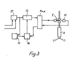
- a delay device of an electromagnetic control valve 7 according to the invention is shown in FIG. 3.
- the delay device according to the invention has a first delay element 12 with a constant delay time, which is preferably 2.56 ms, a second delay element 13 with a variable delay time, a circuit breaker 14a, a device 15 with a conditioning unit 14b for detecting the armature movement of the control valve 7, which for example consists of can consist of a permanent magnet, an induction coil and associated pole pieces and in a manner known per se generates control signals due to the change in a magnetic resistance, for example, and a phase discriminator 16.
- the control pulse of the measured value processing device which is adjusted according to the invention to the constant delay time as a function of the speed by the circuit arrangement shown in FIG.
- phase discriminator 16 is supplied via a bistable flip-flop 17 on the one hand to the first delay element 12 and on the other hand to the second delay element 13. After a constant delay time of 2.56 ms, the delay element 12 supplies an output signal to the phase discriminator 16. Via the second delay element 13 and the circuit breaker 14a, the control pulse of the measured value processing device is fed to the electromagnetic control valve 7. After a valve-specific delay time, the control valve 7 reacts to the control pulse of the measured value processing device, the armature movement of the electromagnetic valve 7 in the device 14 generating an output signal which can be supplied as an actual value to the phase discriminator 16 via the processing unit 14b.
- the phase discriminator 16 which will be explained in more detail in connection with the description of FIG.
- a circuit which represents the constant delay time of the electromagnetic control valve 7 as a function of the actual speed of the internal combustion engine and the triggering time of the control valve in the opening and / or closing direction determined by the electrically working measured value processing device as a function of the constant delay time of the control valve changed.
- 18 denotes a frequency multiplier, to which the pulse trains determined by the sensor device 10 (FIG. 1) are fed via the line 11.
- the pulse sequences are on the one hand twenty times, which are thus supplied as 0.05 ° crankshaft angle range pulses via a line 19 to an AND gate 20, and on the other hand ten times, which are thus as 0.1 1 crankshaft angle range pulses on an OR gate 21 can be supplied via a line 22 and a sequence controller 23 via a line 24.
- the sequencer 23 is also connected to a switching stage 26 via the line 250.
- the AND gate 20 is controlled via a line 25 by the switching stage 26 provided with a timer, the timer of the switching stage 26 being matched to the constant delay time of the first delay element 12 (FIG. 3) and to the different frequency multiplication within the frequency multiplier 18 .
- the timer is designed for half the constant delay time of 1.28 ms.
- the 0.05 ° crankshaft angle range pulses are fed via a line 27 to a first counting device 28, which continuously determines the o, o5 ° pulses during the switch-on time of 1.28 ms.
- the output of the first counter 28 is a 10-bit data line 29, a memory 30 and a comparator 32 connected via a further 10-bit data line 31.
- the first counting device 28 has an 8-bit input 33 at which a setpoint for the start of injection changes determined by the electrically working measured value processing device is applied.
- an output 34 of sequence controller 23, with 0.1 ° on the line 24 - K urbelwellenwinkel Gebsimpulsen is synchronized by the frequency multiplier 18, connected to the first counting means 28 and via an output 35 to the memory 30th
- a gate circuit 38 is assigned to the comparator 32 via connections 36 and 37, to which an input signal 39 of the sequence controller 23 is also present.
- the gate circuit 38 is connected via a line 40 to a second counting device 41 and via a line 42 to the OR gate 21.
- the second counting device 41 is connected via line 43 to the OR gate 21 and thus to the frequency multiplier 18 and via a 10-bit data line 44 to the memory 30 and continuously determines 0.1 ° crankshaft angle pulse counting intervals by a predeterminable maximum value are limited.
- the synchronous control signal generated by the synchronous mark on the flywheel 3 in the sensor device 10 is also present on the input side via lines 45, 46.
- the 0.05 ° crankshaft angle pulses are counted.
- the measured variable of the next count and the memory content are compared in the comparator 32, and the content of the memory 30 is subjected to a corresponding correction pulse via the connection to the comparator 32 and the line 35, depending on the comparison result, due to the very fast counting rhythm the comparison difference applied to the comparator is a maximum of 1 crankshaft angle pulse and the correction pulse is set in the gap between two 0.1 ° crankshaft angle pulses via the sequence control 23.
- the correction via the comparator 32 and the gate circuit 38 is carried out continuously.
- the memory 30 is set to the current measured variable of the counting device 28 by the synchronizing pulse which is produced in the sensor device 10 and transmitted via the line 47.
- the second counting device counts in parallel to the first counting device 28 the 0.1 ° crankshaft angle pulses generated by the frequency multiplier 18 in continuous counting intervals, which in the present six-cylinder internal combustion engine 1 are limited by the predetermined maximum value of 1,200 counting pulses corresponding to a 120 ° ignition angle range. If at the input 46 of the second counting device 41 the sync pulse signal characterizing the start of the working cycle of the internal combustion engine 1 is present, the content of the memory 30 is set in the second counting device 41 via the 10-bit data line 44, so that the second counting device 41 Fixed predetermined value of 120 ° crankshaft angle range reached earlier accordingly.
- the correction pulses characterizing the changes in the actual speed of internal combustion engine 1 are also fed via gate circuit 38 and OR gate 21 to second counting device 41, with sequence controller 23 ensuring that these correction pulses into the gap between two 0.1 ° - crankshaft angle pulses are set.
- the counting device 41 is given whether the respective correction pulse is added to or subtracted from the counter reading.
- the second counting device 41 generates a control pulse for the start of injection, which is fed to a decoder 49.
- the decoder 49 transmits the start of injection pulse to the bistable flip-flops 17 of the individual delay devices of the electromagnetic control valves 7 of the cylinder units 2 via outputs 491, 492, 493, 494, 495, 496.
- a third counting device 51 is connected via a line 50 to the output 48 of the second counting device 41 and via a line 52 to the output 24 of the frequency multiplier 18, so that the third counting device also counts the 0.1 ° crankshaft angle pulses generated by the frequency multiplier 18 .
- a digital comparison device 53 is provided on the third counting device 51 and is connected to the electrical measured value processing device via an 8-bit input 54.
- the comparison device 53 If the target quantity entered by the third counting device 51 for the spray duration reaches the comparison device 53, the comparison device 53 generates a control pulse for the spray end, which is fed via an output 55 to a second decoder 56, which switches the flip-flops 17 of the individual delay devices controls the respective electromagnetic control valves 7 of the cylinder units 2 in the closing direction via lines 561, 562, 563, 564, 565, 566, the decoder 49 for the start of spraying and the decoder 56 for the end of spraying being controlled by a cylinder counter 57 which is connected via an input 58 is synchronized by the synchronizing pulse generated in the sensor device 10 (FIG. 1). The cylinder counter 57 is connected via a line 59 to the third counting device 51 and is continued by a corresponding switching pulse after the control pulse of the comparison device 53.
- the phase discriminator 16 (FIG. 3) of the individual delay devices of the control valves 7 is explained in more detail.
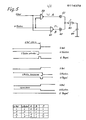
- the control signals U Ref transmitted by the first delay device 12 and the feedback signals U remindm generated by the device 15 for detecting the armature movement of the electromagnetic control valve 7 are respectively on the input side of a NAND link 59 and a NOR link 60. Due to the positive edges of URef and the negative edges of URückm, "high impulses" are generated at outputs A and B when the feedback signal arrives before the constant delay time expires (in the present case 2.56 ms) and when the feedback signal arrives after the constant delay time "low pulses" formed. The temporal width of the pulses is influenced by the time difference between the two input signals.
- the pulses are fed to a capacitor 64 which, depending on the direction ("high” or “low”) and pulse width (duration), forms a charging voltage.
- This charging voltage regulates the second delay element 13 with the variable delay time as a control variable.
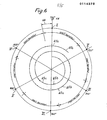
- FIG. 6 shows a flowchart of an operating cycle of the reciprocating piston internal combustion engine 1, with I to VI denoting the inner dead centers of the cylinder units 2 in the firing sequence 1-5-3-6-2-4 as a function of the crankshaft angle, each having an ignition interval of 120 ° crankshaft angle.
- the 1.28 ms turn-on times of the first counting device 28 for determining the 0.55 crankshaft angle pulses and 65b indicate the time intervals in which the memory 30 and the second counting device 41 are indicated by the comparator 32 and the gate circuit 38 are corrected in accordance with the actual speed of the reciprocating piston internal combustion engine 1 determined by the first counting device 28, and the correction pulses are set by the sequence controller 23 into the gap between two successive 0.1 ° crankshaft angle pulses.
- the maximum value that limits the counting intervals of the second counting device 41 is set at 1200 in accordance with the ignition interval.
- the crankshaft angle range is identified by 66, which corresponds to the constant deceleration time of the deceleration device of 2.56 ms at a predetermined actual engine speed and was determined by the first counting device 28 and can be set in the second counter 41 via the synchronizing pulse.
- a setpoint for the start of injection determined by the electrical measured value processing device is also taken into account, so that when the maximum value of the second counting device triggering the start of injection control pulse is reached, the electromagnetic control valve 7 opens exactly, changes in the actual speed of the reciprocating piston internal combustion engine 1 during the working stroke of the reciprocating piston internal combustion engine by means of the Correction impulses caused positive or negative correction is taken into account.
Landscapes
- Engineering & Computer Science (AREA)
- Chemical & Material Sciences (AREA)
- Combustion & Propulsion (AREA)
- Mechanical Engineering (AREA)
- General Engineering & Computer Science (AREA)
- Electrical Control Of Air Or Fuel Supplied To Internal-Combustion Engine (AREA)
- Fuel-Injection Apparatus (AREA)
Priority Applications (1)
| Application Number | Priority Date | Filing Date | Title |
|---|---|---|---|
| AT83112967T ATE40445T1 (de) | 1983-01-25 | 1983-12-22 | Kraftstoffeinspritzvorrichtung fuer brennkraftmaschinen. |
Applications Claiming Priority (2)
| Application Number | Priority Date | Filing Date | Title |
|---|---|---|---|
| DE3302293 | 1983-01-25 | ||
| DE19833302293 DE3302293A1 (de) | 1983-01-25 | 1983-01-25 | Kraftstoffeinspritzvorrichtung fuer brennkraftmaschinen |
Publications (3)
| Publication Number | Publication Date |
|---|---|
| EP0114378A2 true EP0114378A2 (fr) | 1984-08-01 |
| EP0114378A3 EP0114378A3 (en) | 1986-08-20 |
| EP0114378B1 EP0114378B1 (fr) | 1989-01-25 |
Family
ID=6189095
Family Applications (1)
| Application Number | Title | Priority Date | Filing Date |
|---|---|---|---|
| EP83112967A Expired EP0114378B1 (fr) | 1983-01-25 | 1983-12-22 | Dispositif d'injection de carburant pour moteur à combustion interne |
Country Status (5)
| Country | Link |
|---|---|
| US (1) | US4576129A (fr) |
| EP (1) | EP0114378B1 (fr) |
| JP (1) | JPS59176429A (fr) |
| AT (1) | ATE40445T1 (fr) |
| DE (2) | DE3302293A1 (fr) |
Cited By (2)
| Publication number | Priority date | Publication date | Assignee | Title |
|---|---|---|---|---|
| EP0153142A3 (en) * | 1984-02-13 | 1986-11-20 | Leslie Hartridge Limited | A signal generator for use in monitoring a multi-line fuel injection system |
| EP2083159A1 (fr) | 2008-01-28 | 2009-07-29 | GM Global Technology Operations, Inc. | Procédé pour la commande d'injecteurs de carburant actionnés par solénoïde de moteurs à combustion interne |
Families Citing this family (10)
| Publication number | Priority date | Publication date | Assignee | Title |
|---|---|---|---|---|
| US4790277A (en) * | 1987-06-03 | 1988-12-13 | Ford Motor Company | Self-adjusting fuel injection system |
| DE3805033A1 (de) * | 1988-02-18 | 1989-08-31 | Bosch Gmbh Robert | Kraftstoffeinspritzpumpe fuer brennkraftmaschinen |
| US5738071A (en) * | 1991-05-22 | 1998-04-14 | Wolff Controls Corporation | Apparatus and method for sensing movement of fuel injector valve |
| US5325837A (en) * | 1992-11-19 | 1994-07-05 | Robert Bosch Gmbh | Fuel injection apparatus for internal combustion engines |
| JPH08210209A (ja) * | 1995-02-06 | 1996-08-20 | Zexel Corp | 高圧燃料噴射装置 |
| US5765120A (en) * | 1997-02-05 | 1998-06-09 | Brymen Technology Corporation | Detecting device for fuel-injecting interval of engine |
| JP2002004913A (ja) * | 2000-06-26 | 2002-01-09 | Nissan Motor Co Ltd | 圧縮自己着火式内燃機関 |
| US8444060B2 (en) * | 2007-07-17 | 2013-05-21 | Mi Yan | Fuel injector with deterioration detection |
| AT10301U3 (de) * | 2008-09-01 | 2009-09-15 | Avl List Gmbh | Verfahren und regelanordnung zur regelung einer regelstrecke mit sich wiederholendem arbeitszyklus |
| DE102010021640B4 (de) | 2010-05-26 | 2024-09-12 | Aventics Gmbh | Verfahren und Vorrichtung zur Ansteuerung einer Armatur |
Family Cites Families (16)
| Publication number | Priority date | Publication date | Assignee | Title |
|---|---|---|---|---|
| FR2059768A5 (fr) * | 1969-05-14 | 1971-06-04 | Barat J | |
| GB1441262A (en) * | 1972-10-04 | 1976-06-30 | Cav Ltd | Fuel pumping apparatus |
| GB1465052A (en) * | 1973-02-20 | 1977-02-23 | Lucas Electrical Ltd | Fuel control systems |
| GB1528744A (en) * | 1974-10-25 | 1978-10-18 | Lucas Electrical Ltd | Fuel injection systems for internal combustion engines |
| DE2653046A1 (de) * | 1976-11-23 | 1978-05-24 | Bosch Gmbh Robert | Elektronisches regelverfahren und regelsystem zur bestimmung des spritzbeginns bei dieselmotoren |
| JPS5578131A (en) * | 1978-12-06 | 1980-06-12 | Nissan Motor Co Ltd | Fuel ejection control device |
| JPS6011220B2 (ja) * | 1978-12-06 | 1985-03-23 | 日産自動車株式会社 | 燃料噴射装置 |
| GB2041573B (en) * | 1979-02-08 | 1983-04-13 | Lucas Industries Ltd | Fuel injection system for internal combustion engines |
| US4335695A (en) * | 1979-10-01 | 1982-06-22 | The Bendix Corporation | Control method for internal combustion engines |
| JPS5652533A (en) * | 1979-10-04 | 1981-05-11 | Nissan Motor Co Ltd | Injection timing selecting device |
| JPS56159530A (en) * | 1980-05-13 | 1981-12-08 | Diesel Kiki Co Ltd | Injection controller for fuel injection valve of internal- combustion engine |
| JPS575526A (en) * | 1980-06-11 | 1982-01-12 | Diesel Kiki Co Ltd | Method of detecting injection flow in fuel injection valve |
| DE3039967A1 (de) * | 1980-10-23 | 1982-06-03 | Robert Bosch Gmbh, 7000 Stuttgart | Kraftstoffeinspritzanlage |
| US4327695A (en) * | 1980-12-22 | 1982-05-04 | Ford Motor Company | Unit fuel injector assembly with feedback control |
| US4364351A (en) * | 1981-05-18 | 1982-12-21 | General Motors Corporation | Diesel engine fuel limiting system |
| DE3151889C2 (de) * | 1981-12-30 | 1983-12-22 | M.A.N. Maschinenfabrik Augsburg-Nürnberg AG, 8900 Augsburg | Brennstoffeinspritzsystem an einer Brennkraftmaschine |
-
1983
- 1983-01-25 DE DE19833302293 patent/DE3302293A1/de not_active Withdrawn
- 1983-12-22 EP EP83112967A patent/EP0114378B1/fr not_active Expired
- 1983-12-22 DE DE8383112967T patent/DE3379069D1/de not_active Expired
- 1983-12-22 AT AT83112967T patent/ATE40445T1/de not_active IP Right Cessation
-
1984
- 1984-01-23 JP JP59008642A patent/JPS59176429A/ja active Pending
- 1984-01-25 US US06/573,802 patent/US4576129A/en not_active Expired - Fee Related
Cited By (3)
| Publication number | Priority date | Publication date | Assignee | Title |
|---|---|---|---|---|
| EP0153142A3 (en) * | 1984-02-13 | 1986-11-20 | Leslie Hartridge Limited | A signal generator for use in monitoring a multi-line fuel injection system |
| EP2083159A1 (fr) | 2008-01-28 | 2009-07-29 | GM Global Technology Operations, Inc. | Procédé pour la commande d'injecteurs de carburant actionnés par solénoïde de moteurs à combustion interne |
| US8011351B2 (en) | 2008-01-28 | 2011-09-06 | GM Global Technology Operations LLC | Method for driving solenoid-actuated fuel injectors of internal combustion engines |
Also Published As
| Publication number | Publication date |
|---|---|
| DE3302293A1 (de) | 1984-07-26 |
| US4576129A (en) | 1986-03-18 |
| EP0114378B1 (fr) | 1989-01-25 |
| DE3379069D1 (en) | 1989-03-02 |
| ATE40445T1 (de) | 1989-02-15 |
| EP0114378A3 (en) | 1986-08-20 |
| JPS59176429A (ja) | 1984-10-05 |
Similar Documents
| Publication | Publication Date | Title |
|---|---|---|
| DE2739223C2 (de) | Elektrisch gesteuerte Kraftstoffeinspritzanlage für eine Brennkraftmaschine | |
| DE2800433A1 (de) | Einrichtung zur drehzahlbegrenzung einer brennkraftmaschine | |
| DE3125466A1 (de) | Brennstoff-einspritzvorrichtung fuer eine brennkraftmaschine | |
| EP0241697A1 (fr) | Dispositif d'injection du combustible pour moteurs à combustion interne | |
| DE2013703A1 (de) | Einrichtung zur elektronischen Erzeugung und Verstellung des Zündzeitpunktes von Zündanlagen in Brennkraftmaschinen | |
| DE3536207C5 (de) | Kraftstoff-Steuersystem für einen Mehrzylinder-Dieselmotor | |
| EP0114378B1 (fr) | Dispositif d'injection de carburant pour moteur à combustion interne | |
| DE2845357C2 (fr) | ||
| DE4128909C2 (de) | Verfahren zur Zündzeitpunktsteuerung für eine Brennkraftmaschine | |
| DE3338297C2 (fr) | ||
| DE4004110C2 (de) | Verfahren und Einrichtung zur Steuerung einer magnetventilgesteuerten Kraftstoffpumpe | |
| EP1313936B1 (fr) | Procede et dispositif de commande d'un moteur a combustion interne | |
| DE19513597C2 (de) | Verfahren zur Zylindererkennung bei einer Brennkraftmaschine | |
| DE2619556A1 (de) | Zuendanlage, insbesondere fuer brennkraftmaschinen | |
| EP0898068B1 (fr) | Méthode et dispositif pour contrôler l'injection de carburant d'un moteur à combustion d'un véhicule | |
| DE4340614A1 (de) | Vorrichtung zur Verdrehung einer Nockenwelle gegenüber der Kurbelwelle in Kraftfahrzeugen | |
| DE10330705B4 (de) | Verfahren und Vorrichtung zur Steuerung einer Brennkraftmaschine | |
| DE2748663C2 (fr) | ||
| DE3533529C2 (fr) | ||
| DE4301709C2 (de) | Verfahren und Baugruppe zur Überwachung der Zuverlässigkeit der Regelung der Einspritzung der Zylinder von Verbrennungsmotoren | |
| WO2003100235A1 (fr) | Procede de commande d'un actionneur et dispositif commande associe | |
| EP0077777B1 (fr) | Circuit pour l'introduction de donnees de reference dans des systemes numeriques | |
| EP0023960B1 (fr) | Dispositif d'allumage électronique pour moteur à combustion interne | |
| DE2237017C3 (fr) | ||
| DE2023705C3 (de) | Kraftstoffsteuersystem für Brennkraftmaschinen |
Legal Events
| Date | Code | Title | Description |
|---|---|---|---|
| PUAI | Public reference made under article 153(3) epc to a published international application that has entered the european phase |
Free format text: ORIGINAL CODE: 0009012 |
|
| AK | Designated contracting states |
Designated state(s): AT DE FR GB |
|
| PUAL | Search report despatched |
Free format text: ORIGINAL CODE: 0009013 |
|
| AK | Designated contracting states |
Kind code of ref document: A3 Designated state(s): AT DE FR GB |
|
| 17P | Request for examination filed |
Effective date: 19860709 |
|
| 17Q | First examination report despatched |
Effective date: 19861127 |
|
| GRAA | (expected) grant |
Free format text: ORIGINAL CODE: 0009210 |
|
| AK | Designated contracting states |
Kind code of ref document: B1 Designated state(s): AT DE FR GB |
|
| REF | Corresponds to: |
Ref document number: 40445 Country of ref document: AT Date of ref document: 19890215 Kind code of ref document: T |
|
| REF | Corresponds to: |
Ref document number: 3379069 Country of ref document: DE Date of ref document: 19890302 |
|
| ET | Fr: translation filed | ||
| GBT | Gb: translation of ep patent filed (gb section 77(6)(a)/1977) | ||
| PGFP | Annual fee paid to national office [announced via postgrant information from national office to epo] |
Ref country code: FR Payment date: 19891108 Year of fee payment: 7 Ref country code: AT Payment date: 19891108 Year of fee payment: 7 |
|
| PLBE | No opposition filed within time limit |
Free format text: ORIGINAL CODE: 0009261 |
|
| STAA | Information on the status of an ep patent application or granted ep patent |
Free format text: STATUS: NO OPPOSITION FILED WITHIN TIME LIMIT |
|
| PGFP | Annual fee paid to national office [announced via postgrant information from national office to epo] |
Ref country code: GB Payment date: 19891130 Year of fee payment: 7 |
|
| PGFP | Annual fee paid to national office [announced via postgrant information from national office to epo] |
Ref country code: DE Payment date: 19891212 Year of fee payment: 7 |
|
| 26N | No opposition filed | ||
| PG25 | Lapsed in a contracting state [announced via postgrant information from national office to epo] |
Ref country code: GB Effective date: 19901222 Ref country code: AT Effective date: 19901222 |
|
| GBPC | Gb: european patent ceased through non-payment of renewal fee | ||
| PG25 | Lapsed in a contracting state [announced via postgrant information from national office to epo] |
Ref country code: FR Effective date: 19910830 |
|
| PG25 | Lapsed in a contracting state [announced via postgrant information from national office to epo] |
Ref country code: DE Effective date: 19910903 |
|
| REG | Reference to a national code |
Ref country code: FR Ref legal event code: ST |