EP0114445B1 - Stapelelement und eine mit einem solchen Stapelelement versehene Tribüne, Podium oder dergleichen - Google Patents
Stapelelement und eine mit einem solchen Stapelelement versehene Tribüne, Podium oder dergleichen Download PDFInfo
- Publication number
- EP0114445B1 EP0114445B1 EP83201849A EP83201849A EP0114445B1 EP 0114445 B1 EP0114445 B1 EP 0114445B1 EP 83201849 A EP83201849 A EP 83201849A EP 83201849 A EP83201849 A EP 83201849A EP 0114445 B1 EP0114445 B1 EP 0114445B1
- Authority
- EP
- European Patent Office
- Prior art keywords
- panel
- legs
- members
- stacking
- portions
- Prior art date
- Legal status (The legal status is an assumption and is not a legal conclusion. Google has not performed a legal analysis and makes no representation as to the accuracy of the status listed.)
- Expired
Links
Images


Classifications
-
- E—FIXED CONSTRUCTIONS
- E04—BUILDING
- E04G—SCAFFOLDING; FORMS; SHUTTERING; BUILDING IMPLEMENTS OR AIDS, OR THEIR USE; HANDLING BUILDING MATERIALS ON THE SITE; REPAIRING, BREAKING-UP OR OTHER WORK ON EXISTING BUILDINGS
- E04G1/00—Scaffolds primarily resting on the ground
- E04G1/14—Comprising essentially pre-assembled two-dimensional [2D] frame-like elements, e.g. of rods in L- or H-shape, with or without bracing
-
- E—FIXED CONSTRUCTIONS
- E04—BUILDING
- E04H—BUILDINGS OR LIKE STRUCTURES FOR PARTICULAR PURPOSES; SWIMMING OR SPLASH BATHS OR POOLS; MASTS; FENCING; TENTS OR CANOPIES, IN GENERAL
- E04H3/00—Buildings or groups of buildings for public or similar purposes; Institutions, e.g. infirmaries or prisons
- E04H3/10—Buildings or groups of buildings for public or similar purposes; Institutions, e.g. infirmaries or prisons for meetings, entertainments, or sports
- E04H3/12—Tribunes, grandstands or terraces for spectators
Definitions
- the present invention relates to a stacking panel for forming gallery seating in combination with a plurality of other such panels for supporting platforms in spaced relation to a flooring, comprising a pair of closed rod-like members each being of substantially the same size as the other and each having generally horizontally disposed top and bottom portions joining with left and right upstanding ends, said members being positioned in side-by side spaced apart relation, each said panel further having at least one substantially U-shaped rod-like element having legs positioned in the space between said members.
- a stacking panel of the above described type is characterized in that the legs of the substabtially U-shaped rod-like elements are in the plane of said panel, the tops of the legs of the said element being positioned between said top portions and defining the spacing between said top portions, said element having a connecting bottom extending between said legs and received between said bottom portions of said members and defining the spacing between said panel bottom portions, said connecting bottom extending below said panel bottom portions so as to be received between the spaced top portions of another one of said panels when one said panel is stacked on top of another such panel.
- the stacking panel is characterized by a pair of said U-shaped elements positioned in transversely spaced relation to each other between said rod-like members.
- the said legs of the U-shaped element are flattened at their tops, transverse to the plane of said panel between the top portions thereof to define a transverse space which exceeds the transverse space between said bottom portions to facilitate reception of a connecting bottom of another said panel stacked thereon.
- a panel comprises two closed rod-like members 1 and 2 bent in the plane of the panel and having round cross-sections.
- the members are interconnected by a plurality of substantially U-shaped rod-like elements 3 (in the present case two). As shown in the drawings, the members 1 and 2 are spaced a greater distance apart at the top than at the bottom. Moreover, the free ends of the legs of each U-shaped element are somewhat more widely apart than the opposite ends. Furthermore, by having the U-shaped element project at the bottom from the circumference of the closed members, the projecting connecting portion 4 can be used for the connection to a superimposed panel.
- the distance between the top and bottom of the two closed members 1 and 2 is different. This difference is obtained by providing the U-shaped elements 3, at the free ends of the legs, transverse to the plane of the panel, for attachment between the members 1 and 2, with broadenings or flatten- ings 5.
- the body of one or each U-shaped wire is provided with a kink 21.
- the vertical end edges of one of the two interconnected closed members 1, 2 are each provided with two hinge loops 6,6 and 7,7.
- the hinge loops 6 are arranged closer together than the loops 7, enabling successive stacking panels to be interconnected by means of a pivot pin, not shown.
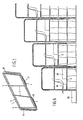
- FIG. 2 shows a stacking element composing four interconnected panels 8, 9, 10 and 11, each pair being of equal length.
- Fig. 3 shows the interconnected panels 8, 9 and a floor plate 12 mounted thereon.
- the floor plate 12 comprises recesses 13 for engagement by the top ends of the panels 8, 9, 10 and 11 therein, thus locking the floor plate relative to the stacking element.
- Fig. 4 shows a hand or guard rail 14 comprising an inverted U-shaped tube 15 whose legs are interconnected for the purpose of reinforcement by a rod 16 extending parallel to the body.
- the rail is provided at the free ends of the legs, with two spaced apart, superimposed hooks 17, which, as shown more in particular in Fig. 5, are dimensioned so as to allow coaction with the outer one of one of the two closed members 1 or 2 of a stacking element.
- each stacking element may be interconnected by short strips 18 at the corners for the purpose of reinforcement.
- Said strips can be provided in such a manner that for attaching the hand or guard rail, first the lower one of said hooks 17 has to be pushed from the bottom onto the respective edge of the panel and subsequently, by lowering the hand or guard rail, the upper hooks onto the respective panel edge.
- the respective strip 18 may then serve as a stop for the hand rail.
- a chair 19 can be mounted on each floor plate 12. To this end the chair may be provided at the bottom with elements, not shown, for attachment in recesses, not shown, in in the floor portions.
- a step 20 may be provided on each floor portion adjacent the entrance or "stairway".
Landscapes
- Engineering & Computer Science (AREA)
- Architecture (AREA)
- Civil Engineering (AREA)
- Structural Engineering (AREA)
- Mechanical Engineering (AREA)
- Floor Finish (AREA)
- Cathode-Ray Tubes And Fluorescent Screens For Display (AREA)
- Road Paving Structures (AREA)
- Apparatus For Radiation Diagnosis (AREA)
- Combinations Of Kitchen Furniture (AREA)
Claims (4)
Priority Applications (1)
| Application Number | Priority Date | Filing Date | Title |
|---|---|---|---|
| AT83201849T ATE27634T1 (de) | 1982-12-29 | 1983-12-29 | Stapelelement und eine mit einem solchen stapelelement versehene tribuene, podium oder dergleichen. |
Applications Claiming Priority (2)
| Application Number | Priority Date | Filing Date | Title |
|---|---|---|---|
| NL8205033A NL8205033A (nl) | 1982-12-29 | 1982-12-29 | Stapelelement en van een dergelijk stapelelement voorziene tribune, podium of dergelijke. |
| NL8205033 | 1982-12-29 |
Publications (3)
| Publication Number | Publication Date |
|---|---|
| EP0114445A2 EP0114445A2 (de) | 1984-08-01 |
| EP0114445A3 EP0114445A3 (en) | 1984-08-22 |
| EP0114445B1 true EP0114445B1 (de) | 1987-06-03 |
Family
ID=19840817
Family Applications (1)
| Application Number | Title | Priority Date | Filing Date |
|---|---|---|---|
| EP83201849A Expired EP0114445B1 (de) | 1982-12-29 | 1983-12-29 | Stapelelement und eine mit einem solchen Stapelelement versehene Tribüne, Podium oder dergleichen |
Country Status (5)
| Country | Link |
|---|---|
| US (1) | US4615277A (de) |
| EP (1) | EP0114445B1 (de) |
| AT (1) | ATE27634T1 (de) |
| DE (1) | DE3371922D1 (de) |
| NL (1) | NL8205033A (de) |
Families Citing this family (2)
| Publication number | Priority date | Publication date | Assignee | Title |
|---|---|---|---|---|
| US5820110A (en) * | 1997-03-11 | 1998-10-13 | B & R Erectors, Inc. | Self storing guard rail system for telescopic bleachers |
| US8915383B2 (en) * | 2012-02-15 | 2014-12-23 | Target Brands, Inc. | Ready-to-assemble plant stand |
Citations (1)
| Publication number | Priority date | Publication date | Assignee | Title |
|---|---|---|---|---|
| US4391378A (en) * | 1981-10-09 | 1983-07-05 | The Sherwood Corporation | Shelving console furniture |
Family Cites Families (28)
| Publication number | Priority date | Publication date | Assignee | Title |
|---|---|---|---|---|
| CA725970A (en) * | 1966-01-18 | A. Evans George | Folding chairs on telescoping structure | |
| US1555022A (en) * | 1923-11-17 | 1925-09-29 | John C Proctor | Apparatus for handling building material |
| US2239483A (en) * | 1940-02-20 | 1941-04-22 | Marathon Paper Mills Co | Receiving and supporting receptacle for bulk ice cream distortable cartons |
| US2611422A (en) * | 1947-07-28 | 1952-09-23 | Safway Steel Products Inc | Demountable grandstand seat planks |
| FR1052278A (fr) * | 1952-03-11 | 1954-01-22 | Gradins démontables | |
| US2660328A (en) * | 1952-09-29 | 1953-11-24 | Union Steel Prod Co | Collapsible stacking receptacle |
| DE945346C (de) * | 1954-11-26 | 1956-07-05 | Carl Friedrich Gernhard | Tribuene aus Fertigteilen |
| BE564912A (de) * | 1957-02-18 | |||
| US2985332A (en) * | 1958-05-12 | 1961-05-23 | Nathan Gilbert | Collapsible container |
| CH378006A (it) * | 1960-06-30 | 1964-05-31 | Plastifil S A | Scaffalatura scomponibile e componibile segnatamente per l'esposizione e la vendita di merci |
| US3139987A (en) * | 1962-02-28 | 1964-07-07 | Rubio Santiago | Knockdown structure and component frame therefor |
| FR1344507A (fr) * | 1962-10-19 | 1963-11-29 | Prod Chim Des Francs | Meuble-étagère extensible à éléments qui peuvent être empilés par emboîtement |
| US3270997A (en) * | 1964-03-19 | 1966-09-06 | Kenneth W Gethmann | Scaffold device |
| US3314549A (en) * | 1964-08-24 | 1967-04-18 | Goldreich Paul | Collapsible shipping-display unit |
| US3318461A (en) * | 1965-05-10 | 1967-05-09 | Howard J Marschak | Display stand |
| FR1468235A (fr) * | 1966-02-15 | 1967-02-03 | Access Equipment Ltd | Charpente pour échafaudages ou constructions similaires |
| US3394963A (en) * | 1966-09-30 | 1968-07-30 | Louis A. Antonioli | Foldaway seating platform |
| US3489385A (en) * | 1968-02-02 | 1970-01-13 | Ernest F Dill Jr | General utility basket |
| US3897516A (en) * | 1970-04-06 | 1975-07-29 | Stauffer Chemical Co | Oximino phosphorus compounds |
| US3680712A (en) * | 1970-09-21 | 1972-08-01 | Eagle Picher Ind Inc | Modular display rack |
| US3704791A (en) * | 1971-02-24 | 1972-12-05 | Ira Bruce Young Jr | Wire correspondence tray |
| FR2133000A5 (de) * | 1971-04-05 | 1972-11-24 | Merle Vignau Jean | |
| GB1557178A (en) * | 1976-10-01 | 1979-12-05 | Locker Wire Products Ltd | Racking |
| US4106626A (en) * | 1976-10-26 | 1978-08-15 | Cari-All, Inc. | Stackable material handling container |
| FR2379444A1 (fr) * | 1977-02-04 | 1978-09-01 | Mebunik Sa | Nouveau panier pliant |
| US4361991A (en) * | 1980-03-24 | 1982-12-07 | Harold Wiese | Seating and guard rail structure for bleachers |
| US4508300A (en) * | 1982-09-23 | 1985-04-02 | Wolff Wire Corporation | Support bracket for accessory beam |
| US4498595A (en) * | 1982-09-28 | 1985-02-12 | Wilson Roland B | Ice block making and storage system |
-
1982
- 1982-12-29 NL NL8205033A patent/NL8205033A/nl not_active Application Discontinuation
-
1983
- 1983-12-22 US US06/564,592 patent/US4615277A/en not_active Expired - Fee Related
- 1983-12-29 EP EP83201849A patent/EP0114445B1/de not_active Expired
- 1983-12-29 DE DE8383201849T patent/DE3371922D1/de not_active Expired
- 1983-12-29 AT AT83201849T patent/ATE27634T1/de not_active IP Right Cessation
Patent Citations (1)
| Publication number | Priority date | Publication date | Assignee | Title |
|---|---|---|---|---|
| US4391378A (en) * | 1981-10-09 | 1983-07-05 | The Sherwood Corporation | Shelving console furniture |
Also Published As
| Publication number | Publication date |
|---|---|
| NL8205033A (nl) | 1984-07-16 |
| EP0114445A3 (en) | 1984-08-22 |
| DE3371922D1 (en) | 1987-07-09 |
| EP0114445A2 (de) | 1984-08-01 |
| US4615277A (en) | 1986-10-07 |
| ATE27634T1 (de) | 1987-06-15 |
Similar Documents
| Publication | Publication Date | Title |
|---|---|---|
| US3233251A (en) | Pool structure | |
| US4821649A (en) | Sheet metal shelving | |
| JPH0229975Y2 (de) | ||
| US4078664A (en) | Cross bar | |
| US5282669A (en) | Ganging mechanism and stacking bar assembly for stacking chairs | |
| US4577841A (en) | Bent wire spring unit | |
| US4470584A (en) | Box spring assembly | |
| US4408928A (en) | Connector having bending means | |
| IE55045B1 (en) | Constructional system using lost shutterings | |
| EP0204281A2 (de) | Tragestruktur für einen erhöhten Doppelboden | |
| US4570906A (en) | Slat assembly for chain link fence | |
| IE890262L (en) | Fencing assembly | |
| US4883725A (en) | Support frame for storage battery cells | |
| US3465898A (en) | Connections for tiered storage rack units | |
| EP0114445B1 (de) | Stapelelement und eine mit einem solchen Stapelelement versehene Tribüne, Podium oder dergleichen | |
| US4287994A (en) | Wedgable storage rack | |
| CA1302593C (en) | Box spring assembly | |
| CA1159378A (en) | Warehouse pallet | |
| US4112640A (en) | Foot grille | |
| EP0215751A2 (de) | Regale mit ausziehbaren Auflageflächen, insbesondere für Bücher | |
| US2948409A (en) | Rack construction | |
| US4699362A (en) | Spring element | |
| US3996716A (en) | Ceiling grid arrangement and connector used therewith | |
| US3596299A (en) | Spring assembly | |
| US4741445A (en) | Knockdown storage rack with wedge connectors |
Legal Events
| Date | Code | Title | Description |
|---|---|---|---|
| PUAI | Public reference made under article 153(3) epc to a published international application that has entered the european phase |
Free format text: ORIGINAL CODE: 0009012 |
|
| PUAL | Search report despatched |
Free format text: ORIGINAL CODE: 0009013 |
|
| AK | Designated contracting states |
Designated state(s): AT BE CH DE FR GB IT LI LU NL SE |
|
| AK | Designated contracting states |
Designated state(s): AT BE CH DE FR GB IT LI LU NL SE |
|
| 17P | Request for examination filed |
Effective date: 19850221 |
|
| GRAA | (expected) grant |
Free format text: ORIGINAL CODE: 0009210 |
|
| AK | Designated contracting states |
Kind code of ref document: B1 Designated state(s): AT BE CH DE FR GB IT LI LU NL SE |
|
| REF | Corresponds to: |
Ref document number: 27634 Country of ref document: AT Date of ref document: 19870615 Kind code of ref document: T |
|
| ITF | It: translation for a ep patent filed | ||
| REF | Corresponds to: |
Ref document number: 3371922 Country of ref document: DE Date of ref document: 19870709 |
|
| ET | Fr: translation filed | ||
| PG25 | Lapsed in a contracting state [announced via postgrant information from national office to epo] |
Ref country code: LU Free format text: LAPSE BECAUSE OF NON-PAYMENT OF DUE FEES Effective date: 19871231 |
|
| PLBE | No opposition filed within time limit |
Free format text: ORIGINAL CODE: 0009261 |
|
| STAA | Information on the status of an ep patent application or granted ep patent |
Free format text: STATUS: NO OPPOSITION FILED WITHIN TIME LIMIT |
|
| 26N | No opposition filed | ||
| ITTA | It: last paid annual fee | ||
| PGFP | Annual fee paid to national office [announced via postgrant information from national office to epo] |
Ref country code: DE Payment date: 19890120 Year of fee payment: 6 |
|
| PGFP | Annual fee paid to national office [announced via postgrant information from national office to epo] |
Ref country code: FR Payment date: 19891208 Year of fee payment: 7 |
|
| PG25 | Lapsed in a contracting state [announced via postgrant information from national office to epo] |
Ref country code: GB Effective date: 19891229 Ref country code: AT Effective date: 19891229 |
|
| PG25 | Lapsed in a contracting state [announced via postgrant information from national office to epo] |
Ref country code: SE Effective date: 19891230 |
|
| PG25 | Lapsed in a contracting state [announced via postgrant information from national office to epo] |
Ref country code: LI Effective date: 19891231 Ref country code: CH Effective date: 19891231 Ref country code: BE Effective date: 19891231 |
|
| PGFP | Annual fee paid to national office [announced via postgrant information from national office to epo] |
Ref country code: NL Payment date: 19891231 Year of fee payment: 7 |
|
| BERE | Be: lapsed |
Owner name: DE LA HAYE CORNELIS FRANCISCUS Effective date: 19891231 |
|
| GBPC | Gb: european patent ceased through non-payment of renewal fee | ||
| REG | Reference to a national code |
Ref country code: CH Ref legal event code: PL |
|
| PG25 | Lapsed in a contracting state [announced via postgrant information from national office to epo] |
Ref country code: DE Effective date: 19900901 |
|
| PG25 | Lapsed in a contracting state [announced via postgrant information from national office to epo] |
Ref country code: NL Effective date: 19910701 |
|
| NLV4 | Nl: lapsed or anulled due to non-payment of the annual fee | ||
| PG25 | Lapsed in a contracting state [announced via postgrant information from national office to epo] |
Ref country code: FR Effective date: 19910830 |
|
| REG | Reference to a national code |
Ref country code: FR Ref legal event code: ST |
|
| EUG | Se: european patent has lapsed |
Ref document number: 83201849.3 Effective date: 19900830 |