EP0114464B1 - Coupler for modular wiring systems - Google Patents
Coupler for modular wiring systems Download PDFInfo
- Publication number
- EP0114464B1 EP0114464B1 EP83306968A EP83306968A EP0114464B1 EP 0114464 B1 EP0114464 B1 EP 0114464B1 EP 83306968 A EP83306968 A EP 83306968A EP 83306968 A EP83306968 A EP 83306968A EP 0114464 B1 EP0114464 B1 EP 0114464B1
- Authority
- EP
- European Patent Office
- Prior art keywords
- cavity
- contact
- coupler
- plug
- housing
- Prior art date
- Legal status (The legal status is an assumption and is not a legal conclusion. Google has not performed a legal analysis and makes no representation as to the accuracy of the status listed.)
- Expired
Links
Images


Classifications
-
- H—ELECTRICITY
- H01—ELECTRIC ELEMENTS
- H01R—ELECTRICALLY-CONDUCTIVE CONNECTIONS; STRUCTURAL ASSOCIATIONS OF A PLURALITY OF MUTUALLY-INSULATED ELECTRICAL CONNECTING ELEMENTS; COUPLING DEVICES; CURRENT COLLECTORS
- H01R4/00—Electrically-conductive connections between two or more conductive members in direct contact, i.e. touching one another; Means for effecting or maintaining such contact; Electrically-conductive connections having two or more spaced connecting locations for conductors and using contact members penetrating insulation
- H01R4/28—Clamped connections, spring connections
- H01R4/48—Clamped connections, spring connections utilising a spring, clip, or other resilient member
- H01R4/4809—Clamped connections, spring connections utilising a spring, clip, or other resilient member using a leaf spring to bias the conductor toward the busbar
-
- H—ELECTRICITY
- H01—ELECTRIC ELEMENTS
- H01R—ELECTRICALLY-CONDUCTIVE CONNECTIONS; STRUCTURAL ASSOCIATIONS OF A PLURALITY OF MUTUALLY-INSULATED ELECTRICAL CONNECTING ELEMENTS; COUPLING DEVICES; CURRENT COLLECTORS
- H01R31/00—Coupling parts supported only by co-operation with counterpart
-
- H—ELECTRICITY
- H01—ELECTRIC ELEMENTS
- H01R—ELECTRICALLY-CONDUCTIVE CONNECTIONS; STRUCTURAL ASSOCIATIONS OF A PLURALITY OF MUTUALLY-INSULATED ELECTRICAL CONNECTING ELEMENTS; COUPLING DEVICES; CURRENT COLLECTORS
- H01R11/00—Individual connecting elements providing two or more spaced connecting locations for conductive members which are, or may be, thereby interconnected, e.g. end pieces for wires or cables supported by the wire or cable and having means for facilitating electrical connection to some other wire, terminal, or conductive member, blocks of binding posts
- H01R11/01—Individual connecting elements providing two or more spaced connecting locations for conductive members which are, or may be, thereby interconnected, e.g. end pieces for wires or cables supported by the wire or cable and having means for facilitating electrical connection to some other wire, terminal, or conductive member, blocks of binding posts characterised by the form or arrangement of the conductive interconnection between the connecting locations
-
- H—ELECTRICITY
- H01—ELECTRIC ELEMENTS
- H01R—ELECTRICALLY-CONDUCTIVE CONNECTIONS; STRUCTURAL ASSOCIATIONS OF A PLURALITY OF MUTUALLY-INSULATED ELECTRICAL CONNECTING ELEMENTS; COUPLING DEVICES; CURRENT COLLECTORS
- H01R2201/00—Connectors or connections adapted for particular applications
- H01R2201/16—Connectors or connections adapted for particular applications for telephony
Definitions
- This invention relates to a coupler for modular wiring systems.
- Modularity is used widely in telephone systems and allows a customer to move a telephone from room to room or to install new telephones and new cords as desired.
- European Patent Application EP-A-0027044 describes the internal wiring installation for telephone handsets and describes a very useful coupler for use with such installations.
- Flexible contact elements are mounted in the coupler housing and the elements are contacted by plug members inserted into respective cavities in the housing.
- the contact portions of the elements are bent over end portions which have sufficient flexibility to permit repeated insertion and withdrawal of the plugs without deforming the contacts.
- An object of the present invention is to provide a coupler in which three plugs each of which can be shown in EP-A-0027044, can access each contact element.
- a coupler for modular wiring systems comprising a housing of dielectric material, a resilient metal contact element mounted in the housing and having a contact portion adjacent to each end of the element, each contact portion being located within a respective contact member receiving cavity so that each contact member when inserted into a respective cavity engages one of the contact portions, the coupler further comprises supports for supporting the element with a configuration determined to provide a flexible section of the element between the supports, and a third contact member receiving cavity with at least a part of the said flexible section located therein and providing a contact portion for engagement by a contact member to be inserted therein, the said configuration being such as to permit deflection of the element upon insertion of the contact member into the third cavity without permanently deforming the element.
- each contact element intermediate its ends is formed with a loop having a configuration which is predetermined to control the deflection characteristics of the contact element.
- the loops shift to allow sufficient deflection to accommodate the plug terminals with suitable contact pressure being developed between the contact elements and the terminals without permanently deforming the contact elements.
- terminal contact in the third cavity does not cause the ends of the contact elements to be repositioned to a degree which adversely effects their engagement with terminal blades of plugs inserted into the other cavities.
- FIG. 1 there is shown a modular tricoupler 30 used to interconnect modular plugs 31-31 that terminate cords of customer station equipment.
- a telephone set interconnected by plugs and couplers is shown in EP-A-0027044.
- the modular plug 31 may be as shown, for example, in U.S.-A-4,148,539.
- the tricoupler 30 facilities the wiring of a premises in a loop. If an outage occurs on one side of any tricoupler 30 in the loop, service is continued from that coupler back to the entry tricoupler because of its connection to the other side of the loop and the entry tricoupler.
- Each of a plurality of terminal-receiving slots in the plug 31 is adapted to receive a blade-like terminal with a surface for engaging conductive portion of a conductor and the terminal.
- An edge surface 63 having curved crowns 64-64 completes an associated contact element within the modular tricoupler 30.
- the tricoupler 30 includes a dielectric housing 80 having plug-receiving cavities 82, 83 and 87.
- the tricoupler 30 may be somewhat non-symmetrical about a vertical axis through the cavity 87. However, in other embodiments, the cavities 82 and 83 may be aligned and the only non- symmetry occurs because of internal portions of the housing 80.
- the housing 80 has mounting lugs 85.
- the axes of the cavities can be arranged at an angle of about 120° to one another.
- the housing 80 may be modified to cause a portion 88 adjacent to the cavity 83 to be as close to the entrance of the cavity 87 as is a surface 89 of the end portion 84. This prevents any rocking of the tricoupler 30 during insertion of a modular plug 31 into the cavity 87.
- the tricoupler 30 also includes a plurality of metallic contact elements 90-90.
- the contact elements 90-90 may be made from a resilient metallic material such as Phosphor bronze.
- the contact elements 90-90 make electrical connections with terminals of modular plugs 31-31 that have been inserted into the cavities 82, 83 and 87.
- the housing 80 of the tricoupler 30 is unipartite and includes a cover 91 and a base 92, and sidewalls 93 and 94.
- a plurality of partitions 96-96 extend from the surface 89 internally through the housing 80.
- the partitions 96-96 are maintained spaced apart by a plurality of separators 97-97 which are interposed between the partitions.
- the partitions 96-96 and the separators 97-97 provide compartments for receiving the contact elements 90-90 to maintain them spaced apart and to provide suitable dielectric protection therebetween.
- the molded cavities 82, 83 and 87 are similar, and each include facilities for locking in a modular plug 31. Accordingly, only one of the plug-receiving cavities will be described.
- Sidewalls 93 and 94 each have an abutment 101 (see FIGS. 2 and 3) with a vertical face 102.
- the vertical face 102 intersects a first ledge 103 which extends to the open end of the cavity 83.
- a second ledge 104 which is closer to an outwardly facing surface 106 of the base 92 than the ledge 103 extends from the partitions 96-96 to a surface 107 to which the cavity 83 opens.
- a ceiling 105 is spaced from the ledges 103-103 a distance which is substantially equal to the distance between the surfaces that defines the height of the plug body 51.
- the cavity 83 is similar to the cavity at each end of a coupler for telephone cords shown in U.S.-A-4,268,109. It includes a recess in an internally formed ledge for allowing the resilient locking tab which is depressed during insertion of a modular plug 31 to spring-return to a normal position. The tab is deflected toward the underside of the plug body to form an arcuate shape so that the underside of the plug 31 can be moved slidably in engagement with side ledge surfaces of a jack cavity of the coupler into which the plug is inserted.
- the molding of the tricoupler 30 of this invention is not so straightforward. It will be recalled that the tricoupler 30 includes a unipartite housing 80 which is substantially less costly than one made of two portions that must be positioned and assembled. Although the one-piece housing 80 facilitates mechanization, access to the interior for molding certain portions becomes a problem. However, provision still must be made for allowing the tab of a plug 31 which is inserted into the tricoupler 30 to return to its normal non-depressed condition to hold the plug in its cavity.
- each sidewall 93 and 94 of the housing 80 is formed to include a third ledge 111 (see FIGS. 2 and 3).
- the ledges 111-111 extend to the external surface 107.
- Each ledge 111 is interrupted by an opening 113 having a rectangular cross-section and extending from the exterior surface 106 of the base 92 into the cavity 83.
- Those side ledge surfaces along which the shoulders of the plug ride are interrupted so that just prior to full insertion of the plug 31, portions of the shoulders clear those ledges allowing the arched tab to resume its original orientation because of its resilience.
- the ledge construction could be made without use of the interrupted portions which form the openings 113-113.
- This structural arrangement of surfaces defining each cavity 82, 83 and 87 facilitates the lock-in of a modular plug 31.
- a modular plug 31 When a modular plug 31 is inserted into a cavity such as the cavity 83, the tab thereof is depressed and bent and has an arched configuration as the flats of the shoulders engage and ride along the ledge portions 111-111.
- the underside of the plug body is moved slidably along the ledges 103-103. The inward movement of the plug body 51 is discontinued when the faces of the recesses engage the surface 102 that extends between the abutment 101 and the ledges 103-103.
- the resilient tab returns to its normal undeflected position causing the shoulders to become disposed in the interrupted portions of the sidewalls along the ledges 111.
- This arrangement resists withdrawal of the plug 31 from the tricoupler 30 because of the engagement of the vertical surfaces of the tab with the vertical surfaces 117-117 which define the openings 113-113.
- Each cavity of the tricoupler 30 is designed to receive and to hold a modular plug 31, and to allow a customer to easily remove it if desired.
- the ease with which plugs 31-31 may be inserted into and removed from the modulartricou- pier 30 facilitates residential and commercial wiring and interconnection of customer station equipment to the network.
- the free end of the tab of the plug 31 extends beyond the surfaces
- the cavity 83 is formed so that with the plug body 51 is proximate engagement with the ceiling 105 and the ledges 103-103, the depression of the tab moves the shoulders a distance so that the flats are disposed substantially at the level of the ledges 111-111 to permit withdrawal of the plug.
- Each of the wire-like contact elements 90-90 includes end portions 121 and 122 received in the cavities 83 and 87.
- the end portions 121 and 122 are disposed in the plug-receiving cavities in a manner such that they are adapted to engage portions of the blade-like terminals of modular plugs 31-31 that are inserted into those cavities.
- each contact element 90 includes a portion 124 which extends through a passageway 125 between an upper portion 126 and one of the plurality of separators 97-97. It will be recalled that each separator 97 is disposed between adjacent partitions 96-96 or between a partition and a sidewall of the housing 80. Each passageway 125 is designed so that a radiused portion 128 of the contact element associated therewith avoids engagement with an adjacent corner 129 of the housing 80.
- each contact element 90 which extends into the cavity 82 of the two generally opposed cavities is specially designed to provide electrical contact with a terminal 60 of a plug 31 without unwanted permanent deformation.
- the contact element In order to compensate for plug housing tolerances and terminal blade variations, particularly of the plug 31 which engages the portion of the contact element 90 intermediate its ends, the contact element must have certain characteristics. It must be capable of deflection with the accompanying build-up internally of reaction forces to accommodate the inserted plug 31 to achieve suitable contact pressure without excessive permanent deformation of segments of the contact element 90. Should the deflection by accompanied by a permanent set, the wire-like contact element 90 would be bent permanently, resulting in reduced circuit contact pressure upon successive plug insertions.
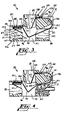
- each contact element 90 that portion of it which extends into the cavity 82 includes a loop 131 which shifts when a portion of it is engaged by a terminal 60.
- a loop 131 By allowing the loop 131 to flex in a relatively short distance between cavities, a permanent set of the wire-like contact element 90 is avoided.
- generous deflection is allowed before the build-up of excessive forces, which could cause a permanent deformation of the wire-like contact element.
- the loop 131 of each contact element 90 is configured to control the deflection characteristics of a portion of the contact element intermediate its ends.
- the loop 131 of each contact element 90 is disposed and supported in its undeflected condition as shown in FIGS. 2 and 3.
- the loop 131 of each contact element 90 includes two segments 132 and 133.
- the segment 132 makes a turn about one of the separators 97-97 positioned between two partitions 96-96 or between a partition and wall of the housing 80. As it makes its turn, it engages and is supported by a corner portion 136 of the separator which spaces apart the partitions 96-96 that form the compartment in which it is positioned.
- This corner portion 136 is a surface which extends transversely between partitions 96-96.
- an opposite corner 137 of the separator 97 is not engaged by the contact element 90 in its turn.
- each contact element 90 is unsupported as its dips downwardly in an offset into a chamber 141 disposed below a portion 142 of the jack cavity 87.
- Each chamber 141 is formed by two adjacent partitions 96-96 or by a partition and an adjacent wall of the housing 80.
- each contact element 90 extends angularly upwardly past, but spaced from, the associated portion 142. Adjacent to the portion 142, the contact element 90 turns at a corner 146 and includes a portion 147 that extends horizontally, as viewed in FIG. 6, through a passageway 148. At the end of the horizontal portion 147, the contact element 90 includes a bend or radiused portion 149 that connects with the retroflexed end portion 121.
- each terminal blade 60 engages a contact element 90 along a portion 143 of the second segment 133 of its loop 131 (see FIG. 4).
- the loop 131 is shifted to the position shown in FIG. 9 where it is spaced from the corner 136 and an opposite corner 137 of the associated separator 97.
- the contact element 90 is able to experience a considerable amount of deflection to accommodate the modular plug 31 while developing suitable contact pressure without any accompanying permanent deformation. If that modular plug 31 is withdrawn from the cavity 82, the loop 131 of the contact element 90 has sufficient resiliency so that it shifts and returns to its original position as shown in FIG. 3.
- the loop 131 is moved without any significant resulting movement in the end portions 121 and 122 which would adversely affect the electrical contact pressure between the contact element 90 and the terminals 60-60 of inserted plugs 31-31. This is accomplished by means of the two passageways 125 and 148.
- each contact element 90 is mounted in the housing 80, one side of the loop 131 engages the corner portion 136 of the plastic separator 97. This positions the loop 131 when the contact element 90 is inserted into the housing and prevents the loop from moving toward the passageway 125 adjacent to the customer cavity 87 when the plug is inserted into the cavity 82.
- the passageway 125 provides suitable confinement for preventing swinging movement of the end portion 122. As a result, there is insubstantial movement of the end portion 122 in the customer jack cavity 87.
- each contact element 90 is formed with a bend upwardly angularly from the chamber 141 and then with a second bend 146 into its associated passageway 148.
- the last-mentioned bend 146 keeps it from moving linearly and the passageway 148 confines it in transverse plane. As a result, there is substantially no movement of the retroflexed end portion 121 in the cavity 83.
Landscapes
- Details Of Connecting Devices For Male And Female Coupling (AREA)
- Connector Housings Or Holding Contact Members (AREA)
Applications Claiming Priority (2)
| Application Number | Priority Date | Filing Date | Title |
|---|---|---|---|
| US442931 | 1982-11-19 | ||
| US06/442,931 US4477141A (en) | 1982-11-19 | 1982-11-19 | Tricoupler for modular wiring systems |
Publications (2)
| Publication Number | Publication Date |
|---|---|
| EP0114464A1 EP0114464A1 (en) | 1984-08-01 |
| EP0114464B1 true EP0114464B1 (en) | 1987-03-11 |
Family
ID=23758744
Family Applications (1)
| Application Number | Title | Priority Date | Filing Date |
|---|---|---|---|
| EP83306968A Expired EP0114464B1 (en) | 1982-11-19 | 1983-11-15 | Coupler for modular wiring systems |
Country Status (9)
| Country | Link |
|---|---|
| US (1) | US4477141A (it) |
| EP (1) | EP0114464B1 (it) |
| JP (1) | JPS59103286A (it) |
| KR (1) | KR930010989B1 (it) |
| CA (1) | CA1201193A (it) |
| DE (1) | DE3370255D1 (it) |
| GB (1) | GB2130819B (it) |
| IT (1) | IT1167589B (it) |
| SG (1) | SG14987G (it) |
Families Citing this family (54)
| Publication number | Priority date | Publication date | Assignee | Title |
|---|---|---|---|---|
| US4566749A (en) * | 1984-08-09 | 1986-01-28 | Brand-Rex Company | Electrical connector receptacle |
| US4611875A (en) * | 1984-08-23 | 1986-09-16 | At&T Information Systems | Communication system cross-connect field power adapter |
| CH668514A5 (de) * | 1985-04-12 | 1988-12-30 | Reichle & De Massari Fa | Montagesteg fuer koaxialkabel-verteileranordnungen von schwachstromanlagen. |
| US4740172A (en) * | 1985-06-11 | 1988-04-26 | Trans World Connections Ltd. | Modular adapter and connector cable for video equipment |
| JPS6258946U (it) * | 1985-09-30 | 1987-04-11 | ||
| JPS6258945U (it) * | 1985-09-30 | 1987-04-11 | ||
| US4657334A (en) * | 1985-10-21 | 1987-04-14 | Simmons Dennis L | Pluggable electrical connector |
| JP2555013B2 (ja) * | 1985-11-01 | 1996-11-20 | 松下電工株式会社 | フリ−アクセスフロアの配線システム |
| JPS62172671A (ja) * | 1986-01-27 | 1987-07-29 | 松下電工株式会社 | 電話線接続用ジヤツク |
| JPH07107864B2 (ja) * | 1986-07-28 | 1995-11-15 | 松下電工株式会社 | モジユラ−ジヤツク |
| US4859201A (en) * | 1986-12-22 | 1989-08-22 | Amp Incorporated | Data communications outlet |
| JPS63198183U (it) * | 1987-06-10 | 1988-12-20 | ||
| GB8725475D0 (en) * | 1987-10-30 | 1987-12-02 | Amp Holland | Modular jack |
| US4950184A (en) * | 1988-04-08 | 1990-08-21 | Panduit Corp. | Wall plate assembly |
| US5013260A (en) * | 1988-04-08 | 1991-05-07 | Panduit Corp. | Communication box assembly |
| US5143868A (en) * | 1988-04-08 | 1992-09-01 | Panduit Corp. | Communication box assembly |
| US4875881A (en) * | 1988-04-08 | 1989-10-24 | Panduit Corp. | Communication box assembly |
| JPH02106686U (it) * | 1989-02-08 | 1990-08-24 | ||
| US5365658A (en) * | 1990-06-27 | 1994-11-22 | Digital Equipment Corporation | Method for forming an electrical interconnection |
| CA2042489C (en) * | 1990-06-27 | 1996-10-01 | Mike Freeman | Wiring distribution system and devices for building wiring |
| US5041018A (en) * | 1990-08-20 | 1991-08-20 | At&T Bell Laboratories | Electrical connector receptacle |
| US5096439A (en) * | 1991-08-28 | 1992-03-17 | At&T Bell Laboratories | Wall plate having jack-release slots |
| US5173061A (en) * | 1992-02-12 | 1992-12-22 | Molex Incorporated | Telecommunications outlet |
| US5578795A (en) * | 1992-05-29 | 1996-11-26 | Canplas Industries Ltd. | Inlet valve assembly for central vacuum system |
| DE4342517C1 (de) * | 1993-12-09 | 1995-05-04 | Krone Ag | Anschlußeinheit für Telekommunikations- und Datenleitungen |
| DE4403730A1 (de) * | 1994-02-07 | 1995-08-10 | Daetwyler System Und Netzwerk | Vorrichtung zur Verbindung von Datennetzverkabelungen |
| US5645449A (en) * | 1995-02-21 | 1997-07-08 | The Whitaker Corporation | Low profile mixed media information outlet |
| US5785551A (en) * | 1995-03-28 | 1998-07-28 | Libby; Robert A. | Quick connect electrical box |
| US5672074A (en) * | 1995-06-22 | 1997-09-30 | Panduit Corp. | Connector mounting receptacles |
| US5741158A (en) * | 1996-07-29 | 1998-04-21 | The Whitaker Corporation | Communications outlet having termination aid platform |
| DE29721064U1 (de) | 1997-12-02 | 1998-03-05 | Müller, Helge Uwe Kurt, 12587 Berlin | Installationsanordnung für Daten- und Telekommunikationsnetze |
| US5975938A (en) * | 1998-06-03 | 1999-11-02 | Robert A. Libby | Quick connect electrical connector for multi conductor insulated cable wiring |
| USD443252S1 (en) | 2000-06-02 | 2001-06-05 | Corning Cable Systems Llc | Wall mount housing |
| US6774307B2 (en) | 2002-05-07 | 2004-08-10 | Applied Technology And Solutions | Through-wall electrical system |
| US6994585B2 (en) | 2003-10-07 | 2006-02-07 | Pass & Seymour, Inc. | Electrical wiring system |
| US7510429B1 (en) | 2003-10-07 | 2009-03-31 | Pass & Seymour, Inc. | Electrical wiring system with slide-in connector |
| US7736175B1 (en) | 2003-10-07 | 2010-06-15 | Pass & Seymour, Inc. | Compact electrical wiring system |
| US7713084B1 (en) | 2003-10-07 | 2010-05-11 | Pass & Seymour, Inc. | Protective electrical wiring device and system |
| US7780470B2 (en) * | 2003-10-07 | 2010-08-24 | Pass & Seymour, Inc. | Plug tail lighting switch and control system |
| US7220143B2 (en) * | 2004-06-02 | 2007-05-22 | Nortel Networks Limited | Overlay to permit delivery of telephony and mission-critical data services to hospital-wide points of care |
| US7163418B2 (en) * | 2004-12-30 | 2007-01-16 | Proprietary Technologies, Inc. | Wall plate comprising signal splitting device |
| US7357652B1 (en) | 2006-10-27 | 2008-04-15 | Leviton Manufacturing Company, Inc. | Modular wiring system with locking elements |
| US7955096B2 (en) | 2006-10-27 | 2011-06-07 | Leviton Manufacturing Company, Inc. | Modular wiring system with locking elements |
| US7666010B2 (en) | 2006-10-27 | 2010-02-23 | Leviton Manufacturing Company, Inc. | Modular wiring system with locking elements |
| ATE508499T1 (de) * | 2006-11-30 | 2011-05-15 | Elbro Ag | Anschlussdosen für audiosysteme |
| CA124948S (en) | 2007-09-01 | 2008-10-20 | Leviton Manufacturing Co | Electrical connector for outlet box |
| CA125027S (en) | 2007-09-24 | 2009-04-06 | Leviton Manufacturing Co | Quick connect electrical receptacle |
| US8344250B2 (en) | 2011-01-20 | 2013-01-01 | Hubbell Incorporated | Low profile electrical device assembly |
| US9099258B2 (en) | 2011-01-20 | 2015-08-04 | Hubbell Incorporated | Rocker contact switch for electrical device |
| DE102011014012A1 (de) * | 2011-03-09 | 2012-12-27 | Mobotix Ag | Steckverbinder |
| US8371863B1 (en) | 2011-07-29 | 2013-02-12 | Leviton Manufacturing Company, Inc. | Modular wiring system |
| AT14207U1 (de) * | 2013-12-19 | 2015-06-15 | Tridonic Gmbh & Co Kg | Vorrichtung zum Kontaktieren von elektrischen Leitern und/oder elektrischen Kontaktelementen, sowie Leuchte oder elektrisches Gerät |
| ITMI20140124U1 (it) * | 2014-03-31 | 2015-10-01 | A S A Plastici Azienda Stampaggio Articoli Plastici S R L | Presa multipla multifunzione. |
| WO2020010095A1 (en) | 2018-07-06 | 2020-01-09 | Hubbell Incorporated | Electrical plug connector and wiring device with keying features |
Family Cites Families (15)
| Publication number | Priority date | Publication date | Assignee | Title |
|---|---|---|---|---|
| US2158004A (en) * | 1936-03-06 | 1939-05-09 | Kingston Products Corp | Electrical connection means |
| US3333231A (en) * | 1965-07-12 | 1967-07-25 | Rogers Corp | Receptacle assemblies |
| US3365696A (en) * | 1965-08-30 | 1968-01-23 | Rogers Corp | Simplified connector for male type terminations |
| GB1442018A (en) * | 1974-08-01 | 1976-07-07 | Itt | Printed circuit board connector |
| US4047787A (en) * | 1977-01-21 | 1977-09-13 | Northern Telecom Limited | Extension cords for plug-in telephones |
| US4061411A (en) * | 1977-01-21 | 1977-12-06 | Northern Telecom Limited | Multi-outlet adaptor for plug-in telephones |
| US4220391A (en) * | 1978-02-23 | 1980-09-02 | Bunker Ramo Corporation | Connector adapter constructions with improved connector and connector mounting arrangement |
| US4146292A (en) * | 1978-03-21 | 1979-03-27 | Superior Cable Corporation | Telephone wall mounting |
| US4153327A (en) * | 1978-05-05 | 1979-05-08 | Northern Telecom Limited | Connector for telephone cords |
| US4241974A (en) * | 1979-05-02 | 1980-12-30 | Western Electric Company, Inc. | Multi-outlet adapter for modular telephone cords |
| US4268109A (en) * | 1979-10-03 | 1981-05-19 | Western Electric Company, Inc. | Coupler for telephone cords |
| US4273402A (en) * | 1979-10-16 | 1981-06-16 | Amp Incorporated | Electrical connector receptacle |
| US4315664A (en) * | 1980-05-05 | 1982-02-16 | Amp Incorporated | Modular jack |
| US4407559A (en) * | 1981-04-09 | 1983-10-04 | Communications Systems, Inc. | Connector device with flush mounting receptacle, cover plate and terminal board |
| US4406509A (en) * | 1981-11-25 | 1983-09-27 | E. I. Du Pont De Nemours & Co. | Jack and plug electrical assembly |
-
1982
- 1982-11-19 US US06/442,931 patent/US4477141A/en not_active Expired - Lifetime
-
1983
- 1983-11-08 CA CA000440708A patent/CA1201193A/en not_active Expired
- 1983-11-15 DE DE8383306968T patent/DE3370255D1/de not_active Expired
- 1983-11-15 EP EP83306968A patent/EP0114464B1/en not_active Expired
- 1983-11-15 GB GB08330417A patent/GB2130819B/en not_active Expired
- 1983-11-18 KR KR1019830005492A patent/KR930010989B1/ko not_active Expired - Fee Related
- 1983-11-18 JP JP58216443A patent/JPS59103286A/ja active Granted
- 1983-11-18 IT IT23784/83A patent/IT1167589B/it active
-
1987
- 1987-02-18 SG SG149/87A patent/SG14987G/en unknown
Also Published As
| Publication number | Publication date |
|---|---|
| SG14987G (en) | 1989-04-21 |
| IT1167589B (it) | 1987-05-13 |
| JPS59103286A (ja) | 1984-06-14 |
| DE3370255D1 (en) | 1987-04-16 |
| EP0114464A1 (en) | 1984-08-01 |
| CA1201193A (en) | 1986-02-25 |
| GB2130819B (en) | 1986-10-29 |
| JPH0131271B2 (it) | 1989-06-23 |
| KR840006735A (ko) | 1984-12-01 |
| GB2130819A (en) | 1984-06-06 |
| KR930010989B1 (ko) | 1993-11-18 |
| GB8330417D0 (en) | 1983-12-21 |
| IT8323784A0 (it) | 1983-11-18 |
| US4477141A (en) | 1984-10-16 |
Similar Documents
| Publication | Publication Date | Title |
|---|---|---|
| US4477141A (en) | Tricoupler for modular wiring systems | |
| US4494815A (en) | Self-aligning cover for modular tricoupler | |
| US5041018A (en) | Electrical connector receptacle | |
| US4239316A (en) | Electrical connectors and assemblies therefor | |
| US4303296A (en) | Modular interface connector | |
| US5096439A (en) | Wall plate having jack-release slots | |
| US5015203A (en) | Power distribution unit having improved junction box | |
| EP0018654B1 (en) | Multi-outlet adapter for modular telephone cords | |
| US4501459A (en) | Electrical connector | |
| US5562493A (en) | Network interface assembly and mounting frame | |
| US4894024A (en) | Telecommunications wall outlets | |
| US5001315A (en) | Circuit breaker auxiliary device snap-on package and method of assembling same | |
| USRE32760E (en) | Electrical connector | |
| EP0112711B1 (en) | Shunt-protected electrical connector | |
| US3842396A (en) | Cluster block housing and pin receptacle | |
| US6056568A (en) | Selectable compatibility electrical connector jack | |
| HUP0105197A2 (en) | Telecommunications jack assembly | |
| US5803756A (en) | Electrical connector with short circuit terminal | |
| HK35092A (en) | Connection block for cable cores, particularly those of telephone cables | |
| EP0522798B1 (en) | Electrical Connector | |
| WO1997019500A1 (en) | Electrical connector with lead positioning comb | |
| EP0057501B1 (en) | Electrical connector assembly for mounting on a printed circuit board | |
| MXPA01010756A (es) | Ensamblaje de combinacion de interruptor y conector de bajo perfil. | |
| EP0142311B1 (en) | Low profile electrical connector assembly | |
| EP0509412B1 (en) | Plural jack connector module |
Legal Events
| Date | Code | Title | Description |
|---|---|---|---|
| PUAI | Public reference made under article 153(3) epc to a published international application that has entered the european phase |
Free format text: ORIGINAL CODE: 0009012 |
|
| AK | Designated contracting states |
Designated state(s): BE DE FR NL SE |
|
| 17P | Request for examination filed |
Effective date: 19840809 |
|
| GRAA | (expected) grant |
Free format text: ORIGINAL CODE: 0009210 |
|
| AK | Designated contracting states |
Kind code of ref document: B1 Designated state(s): BE DE FR NL SE |
|
| REF | Corresponds to: |
Ref document number: 3370255 Country of ref document: DE Date of ref document: 19870416 |
|
| ET | Fr: translation filed | ||
| PLBE | No opposition filed within time limit |
Free format text: ORIGINAL CODE: 0009261 |
|
| STAA | Information on the status of an ep patent application or granted ep patent |
Free format text: STATUS: NO OPPOSITION FILED WITHIN TIME LIMIT |
|
| 26N | No opposition filed | ||
| PGFP | Annual fee paid to national office [announced via postgrant information from national office to epo] |
Ref country code: NL Payment date: 19891130 Year of fee payment: 7 |
|
| PG25 | Lapsed in a contracting state [announced via postgrant information from national office to epo] |
Ref country code: NL Effective date: 19910601 |
|
| NLV4 | Nl: lapsed or anulled due to non-payment of the annual fee | ||
| EAL | Se: european patent in force in sweden |
Ref document number: 83306968.5 |
|
| PGFP | Annual fee paid to national office [announced via postgrant information from national office to epo] |
Ref country code: SE Payment date: 19990927 Year of fee payment: 17 |
|
| PGFP | Annual fee paid to national office [announced via postgrant information from national office to epo] |
Ref country code: BE Payment date: 19991001 Year of fee payment: 17 |
|
| PGFP | Annual fee paid to national office [announced via postgrant information from national office to epo] |
Ref country code: FR Payment date: 19991022 Year of fee payment: 17 |
|
| PGFP | Annual fee paid to national office [announced via postgrant information from national office to epo] |
Ref country code: DE Payment date: 19991231 Year of fee payment: 17 |
|
| PG25 | Lapsed in a contracting state [announced via postgrant information from national office to epo] |
Ref country code: SE Free format text: THE PATENT HAS BEEN ANNULLED BY A DECISION OF A NATIONAL AUTHORITY Effective date: 20001129 |
|
| PG25 | Lapsed in a contracting state [announced via postgrant information from national office to epo] |
Ref country code: BE Free format text: LAPSE BECAUSE OF NON-PAYMENT OF DUE FEES Effective date: 20001130 |
|
| BERE | Be: lapsed |
Owner name: WESTERN ELECTRIC CY INC. Effective date: 20001130 |
|
| EUG | Se: european patent has lapsed |
Ref document number: 83306968.5 |
|
| PG25 | Lapsed in a contracting state [announced via postgrant information from national office to epo] |
Ref country code: FR Free format text: LAPSE BECAUSE OF NON-PAYMENT OF DUE FEES Effective date: 20010731 |
|
| PG25 | Lapsed in a contracting state [announced via postgrant information from national office to epo] |
Ref country code: DE Free format text: LAPSE BECAUSE OF NON-PAYMENT OF DUE FEES Effective date: 20010801 |
|
| REG | Reference to a national code |
Ref country code: FR Ref legal event code: ST |