EP0114519A2 - Dispositif de contrôle des fuites entre les circuits primaires et secondaires d'un réacteur à eau sous pression - Google Patents
Dispositif de contrôle des fuites entre les circuits primaires et secondaires d'un réacteur à eau sous pression Download PDFInfo
- Publication number
- EP0114519A2 EP0114519A2 EP83307895A EP83307895A EP0114519A2 EP 0114519 A2 EP0114519 A2 EP 0114519A2 EP 83307895 A EP83307895 A EP 83307895A EP 83307895 A EP83307895 A EP 83307895A EP 0114519 A2 EP0114519 A2 EP 0114519A2
- Authority
- EP
- European Patent Office
- Prior art keywords
- pressure
- primary
- secondary circuit
- steam generator
- reactor system
- Prior art date
- Legal status (The legal status is an assumption and is not a legal conclusion. Google has not performed a legal analysis and makes no representation as to the accuracy of the status listed.)
- Granted
Links
Images
Classifications
-
- G—PHYSICS
- G21—NUCLEAR PHYSICS; NUCLEAR ENGINEERING
- G21C—NUCLEAR REACTORS
- G21C17/00—Monitoring; Testing ; Maintaining
- G21C17/002—Detection of leaks
-
- F—MECHANICAL ENGINEERING; LIGHTING; HEATING; WEAPONS; BLASTING
- F22—STEAM GENERATION
- F22B—METHODS OF STEAM GENERATION; STEAM BOILERS
- F22B37/00—Component parts or details of steam boilers
- F22B37/02—Component parts or details of steam boilers applicable to more than one kind or type of steam boiler
- F22B37/42—Applications, arrangements or dispositions of alarm or automatic safety devices
-
- Y—GENERAL TAGGING OF NEW TECHNOLOGICAL DEVELOPMENTS; GENERAL TAGGING OF CROSS-SECTIONAL TECHNOLOGIES SPANNING OVER SEVERAL SECTIONS OF THE IPC; TECHNICAL SUBJECTS COVERED BY FORMER USPC CROSS-REFERENCE ART COLLECTIONS [XRACs] AND DIGESTS
- Y02—TECHNOLOGIES OR APPLICATIONS FOR MITIGATION OR ADAPTATION AGAINST CLIMATE CHANGE
- Y02E—REDUCTION OF GREENHOUSE GAS [GHG] EMISSIONS, RELATED TO ENERGY GENERATION, TRANSMISSION OR DISTRIBUTION
- Y02E30/00—Energy generation of nuclear origin
- Y02E30/30—Nuclear fission reactors
Definitions
- This invention relates to a method of controlling leakage between primary and secondary coolant circuits or loops inside a steam generator of a pressurised water reactor system.
- a saturation pressure corresponding to the temperature of the secondary water supply in the steam generator prevails in the secondary circuit or loop of the steam generator.
- the coolant on the primary side of the steam generator has a slightly higher temperature and is kept undercooled by connection to a pressuriser with a substantially higher pressure than the saturation pressure of the primary coolant.
- the pressure on the primary side in the steam generator is necessarily higher than the pressure on the secondary side.
- radioactive primary coolant therefore flows into the secondary side of the steam generator, giving rise to the hazard of liberation of radioactivity as well as flooding of the steam generator.
- leakage is reduced during shutdown of the system by reducing the pressure differential between the primary coolant and the secondary side of the steam generator.
- a method of controlling leakage between primary and secondary coolant circuits inside a steam generator of a pressurised water reactor system the method being characterised by shutting off a live steam line and a feedwater line connected to the secondary circuit, and injecting gas to increase the pressure in the secondary circuit.
- a preferred method embodying this invention and described hereinbelow controls leakage of the type mentioned by bringing about a pressure equalisation (i.e. altering the pressure differential) between the primary coolant circuit and a secondary area of a steam generator, while a pressure margin (referred to herein as a sub-cooling margin) is maintained between the actual and saturation condition of the primary coolant whereby the primary coolant is sub-cooled.
- the method thus produces a pressure equalisation without loss of the sub-cooling margin from saturation of the primary coolant.
- a particular refinement of the method provides that the pressure prevailing in the secondary circuit or area is brought to a value below a permissible steam generator pressure by the injection of gas, and that the primary coolant pressure is lowered to the pressure then prevailing in the secondary circuit. Thus, even in steam generators with a limited permissible pressure, the sub-cooling margin from saturation of the primary coolant may be maintained.
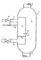
- the single figure of the drawing shows, schematically a steam generator 1 of a pressurised water reactor system (not shown).
- Primary coolant flows through a primary coolant circuit comprising a tube bundle symbolised by a space 2.
- the primary coolant is introduced through a line 3 from a reactor pressure vessel, and is fed back to the vessel through a line 4.
- a secondary circuit of the steam generator is symbolised by a space 5.
- Water introduced through a feedwater line 6 flows around the tube bundle conducting the primary coolant and leaves the steam generator 1 as steam through a live steam line 7.
- the change of the feedwater from the liquid into the vaporised state is indicated by a line 8.
- radioactive primary coolant may reach the secondary circuit 5 of the steam generator since the pressure of the primary coolant is always higher than the pressure in the secondary circuit.
- the position of such a break is illustrated by an opening 9, through which the primary coolant reaches the secondary circuit 5 in the direction of an arrow 10.
- Shutoff valves 11 and 12 positioned in the feedwater and live steam lines 6 and 7 are then closed.
- other auxiliary lines such as blowdown lines, recirculation lines, and drainlines, should be suitably isolated.
- Nitrogen gas is injected into the secondary circuit 5 through a line 13 connected to the steam generator 1 and to a source of gas (not shown), after opening of a shutoff valve 14, until the same pressure prevails there as in the primary circuit 2.
- the pressure present in the secondary circuit 5 is composed of the live steam pressure and the partial pressure of the injected nitrogen gas.
- a sub-cooling margin from saturation pressure which corresponds to the partial pressure of the injected nitrogen gas, can then be maintained in the primary coolant. This is very important since an adequate sub-cooling margin from saturation pressure allows the recator system to be shut down safely through other steam generators.
- gas is not limited to nitrogen gas but is meant to include other suitable gaseous substances such as, for example, steam at a pressure above the saturation pressure of the water in the secondary circuit in those steam generators where such use of steam is suitable, such as those of the U-tube type.
- the secondary circuit 5 of the steam generator 1 for example, is limited to a permissible pressure by a safety valve, then after closing the shutoff valves 11 and 12, only so much gas is injected through the line 13 that the total pressure formed by the partial pressures of live steam and gas lies below the permissible pressure.
- the primary coolant pressure is then brought down to this total pressure of the secondary circuit 5, so that a pressure equalisation also occurs.
- the partial pressure of gas represents a measure of the sub-cooling margin of the primary coolant from the saturation pressure. It may actually be smaller than in the previously described example, but is adequate to allow a safe shutdown of the reactor system through the other steam generators.
Landscapes
- Engineering & Computer Science (AREA)
- Physics & Mathematics (AREA)
- General Engineering & Computer Science (AREA)
- Plasma & Fusion (AREA)
- High Energy & Nuclear Physics (AREA)
- Thermal Sciences (AREA)
- Mechanical Engineering (AREA)
- Structure Of Emergency Protection For Nuclear Reactors (AREA)
- Monitoring And Testing Of Nuclear Reactors (AREA)
- Filling Or Discharging Of Gas Storage Vessels (AREA)
Priority Applications (1)
| Application Number | Priority Date | Filing Date | Title |
|---|---|---|---|
| AT83307895T ATE29573T1 (de) | 1982-12-24 | 1983-12-22 | Leckagesicherungen zwischen primaeren und sekundaeren kreislaeufen eines druckwasserreaktors. |
Applications Claiming Priority (2)
| Application Number | Priority Date | Filing Date | Title |
|---|---|---|---|
| DE3248029A DE3248029C2 (de) | 1982-12-24 | 1982-12-24 | Verfahren zur Verhinderung von Folgeschäden bei Leckagen, die innerhalb eines Dampferzeugers einer Druckwasserreaktoranlage zwischen Primär- und Sekundärkreislauf auftreten |
| DE3248029 | 1982-12-24 |
Publications (3)
| Publication Number | Publication Date |
|---|---|
| EP0114519A2 true EP0114519A2 (fr) | 1984-08-01 |
| EP0114519A3 EP0114519A3 (en) | 1985-11-06 |
| EP0114519B1 EP0114519B1 (fr) | 1987-09-09 |
Family
ID=6181771
Family Applications (1)
| Application Number | Title | Priority Date | Filing Date |
|---|---|---|---|
| EP83307895A Expired EP0114519B1 (fr) | 1982-12-24 | 1983-12-22 | Dispositif de contrôle des fuites entre les circuits primaires et secondaires d'un réacteur à eau sous pression |
Country Status (5)
| Country | Link |
|---|---|
| US (1) | US4612158A (fr) |
| EP (1) | EP0114519B1 (fr) |
| JP (1) | JPS59155789A (fr) |
| AT (1) | ATE29573T1 (fr) |
| DE (2) | DE3248029C2 (fr) |
Cited By (2)
| Publication number | Priority date | Publication date | Assignee | Title |
|---|---|---|---|---|
| EP0146305A3 (en) * | 1983-12-19 | 1986-10-29 | The Babcock & Wilcox Company | Controlling leaks between primary and secondary circuits of a steam generator of a pressurised water reactor system |
| WO1995016879A1 (fr) * | 1993-12-15 | 1995-06-22 | Vy^´Skumny^´ Ústav Jadrovy^´Ch Elektrární A.S. | Commande d'une soupape de suppression de generateur de vapeur |
Families Citing this family (8)
| Publication number | Priority date | Publication date | Assignee | Title |
|---|---|---|---|---|
| RU2203510C2 (ru) * | 2001-05-10 | 2003-04-27 | Государственное предприятие Научно-исследовательский технологический институт им. А.П.Александрова | Способ контроля межконтурной герметичности судовой ядерной энергетической установки с водным теплоносителем |
| RU2300819C2 (ru) * | 2005-08-22 | 2007-06-10 | Федеральное государственное унитарное предприятие "Научно-исследовательский технологический институт им. А.П. Александрова" | Способ контроля герметичности парогенератора судовой ядерной энергетической установки |
| RU2301463C1 (ru) * | 2006-01-10 | 2007-06-20 | Федеральное государственное унитарное предприятие "Научно-исследовательский технологический институт имени А.П. Александрова" | Способ контроля состояния активной зоны судовой ядерной энергетической установки с водным теплоносителем |
| JP2010085282A (ja) * | 2008-09-30 | 2010-04-15 | Toshiba Corp | 加圧水型原子力プラント |
| CN110718313B (zh) * | 2019-09-18 | 2023-08-04 | 上海电力大学 | 一种传热管破裂事故下核电站一回路降温控制方法 |
| RU2754755C1 (ru) * | 2020-12-31 | 2021-09-07 | Александр Прокопьевич Елохин | Способ определения области протечки радиоактивного азота в парогенераторах ядерных реакторов типа клт-40 |
| CN113707349B (zh) * | 2021-09-18 | 2023-06-02 | 福建宁德核电有限公司 | 一种cpr1000机组主蒸汽管线泄漏测量方法及装置 |
| CN114360753B (zh) * | 2021-11-30 | 2025-03-14 | 江苏核电有限公司 | 适用于核电机组工业蒸汽回路的放射性控制系统及方法 |
Family Cites Families (19)
| Publication number | Priority date | Publication date | Assignee | Title |
|---|---|---|---|---|
| US2948516A (en) * | 1950-11-17 | 1960-08-09 | Gen Electric | Heat exchange system with intermediate heat conductive fluids |
| NL255777A (fr) * | 1959-09-10 | |||
| GB951896A (en) * | 1962-02-07 | 1964-03-11 | Soc Anglo Belge Vulcain Sa | Improvements in or relating to nuclear reactor plant |
| DE1208752B (de) * | 1962-06-18 | 1966-01-13 | Koppers Gmbh Heinrich | Turmartiger Gas- oder Winderhitzer |
| US3258403A (en) * | 1963-05-24 | 1966-06-28 | Westinghouse Electric Corp | Nuclear reactor containment system |
| DE1936844C3 (de) * | 1969-07-19 | 1974-03-07 | Siemens Ag, 1000 Berlin U. 8000 Muenchen | Verfahren zur Druckhaltung in Druckwasserreaktoren und Einrichtung zur Durchführung des Verfahrens |
| US3933580A (en) * | 1971-03-08 | 1976-01-20 | Siemens Aktiengesellschaft | Limit regulation system for pressurized water nuclear reactors |
| US4187146A (en) * | 1973-07-11 | 1980-02-05 | Westinghouse Electric Corp. | Reduction of radioactive emissions from nuclear-reactor plant |
| FR2249405B1 (fr) * | 1973-10-24 | 1976-10-01 | Commissariat Energie Atomique | |
| DE2459150C3 (de) * | 1974-12-14 | 1988-07-07 | BBC Brown Boveri AG, 6800 Mannheim | Verfahren und Schaltungsanordnung zur Abfuhr der Nachzerfalls-Wärme eines Druckwasser-Reaktors im Störfall |
| FR2334994A1 (fr) * | 1975-12-09 | 1977-07-08 | Commissariat Energie Atomique | Dispositif de pressurisation a reserve intermediaire |
| DE2613418C3 (de) * | 1976-03-30 | 1981-05-27 | Dipl.-Ing. Paul 6050 Offenbach Morcov | Verfahren und Vorrichtung zur Erzeugung von Hochdruckdampf |
| FR2379881A1 (fr) * | 1977-02-04 | 1978-09-01 | Commissariat Energie Atomique | Bloc-pompe echangeur de chaleur pour reacteurs nucleaires |
| US4104117A (en) * | 1977-02-07 | 1978-08-01 | Westinghouse Electric Corp. | Nuclear reactor power generation |
| JPS53122090A (en) * | 1977-03-31 | 1978-10-25 | Hitachi Ltd | Reactor pressure vessel |
| FR2416532A1 (fr) * | 1978-02-06 | 1979-08-31 | Commissariat Energie Atomique | Perfectionnements aux reacteurs nucleaires a eau pressurisee |
| US4231328A (en) * | 1978-07-18 | 1980-11-04 | Westinghouse Electric Corp. | Automatic steam generator feedwater realignment system |
| US4365664A (en) * | 1980-10-20 | 1982-12-28 | Hughes Aircraft Company | Osmotically pumped heat pipe with passive mixing |
| DE3115344A1 (de) * | 1981-04-15 | 1982-11-04 | Kraftwerk Union AG, 4330 Mülheim | "kuehlung eines dampferzeugers bei einem heizrohrleck" |
-
1982
- 1982-12-24 DE DE3248029A patent/DE3248029C2/de not_active Expired
-
1983
- 1983-12-19 US US06/562,560 patent/US4612158A/en not_active Expired - Fee Related
- 1983-12-22 AT AT83307895T patent/ATE29573T1/de active
- 1983-12-22 EP EP83307895A patent/EP0114519B1/fr not_active Expired
- 1983-12-22 DE DE8383307895T patent/DE3373527D1/de not_active Expired
- 1983-12-23 JP JP58242253A patent/JPS59155789A/ja active Granted
Cited By (2)
| Publication number | Priority date | Publication date | Assignee | Title |
|---|---|---|---|---|
| EP0146305A3 (en) * | 1983-12-19 | 1986-10-29 | The Babcock & Wilcox Company | Controlling leaks between primary and secondary circuits of a steam generator of a pressurised water reactor system |
| WO1995016879A1 (fr) * | 1993-12-15 | 1995-06-22 | Vy^´Skumny^´ Ústav Jadrovy^´Ch Elektrární A.S. | Commande d'une soupape de suppression de generateur de vapeur |
Also Published As
| Publication number | Publication date |
|---|---|
| US4612158A (en) | 1986-09-16 |
| DE3248029C2 (de) | 1987-04-09 |
| ATE29573T1 (de) | 1987-09-15 |
| DE3373527D1 (en) | 1987-10-15 |
| JPS59155789A (ja) | 1984-09-04 |
| EP0114519B1 (fr) | 1987-09-09 |
| JPH031636B2 (fr) | 1991-01-11 |
| EP0114519A3 (en) | 1985-11-06 |
| DE3248029A1 (de) | 1984-07-05 |
Similar Documents
| Publication | Publication Date | Title |
|---|---|---|
| KR100300889B1 (ko) | 가압수형원자로및증기발생기관의누출을완화시키는방법 | |
| EP0114519B1 (fr) | Dispositif de contrôle des fuites entre les circuits primaires et secondaires d'un réacteur à eau sous pression | |
| CA1183614A (fr) | Dispositif de refroidissement d'urgence du coeur d'un reacteur nucleaire refroidi par eau pressurisee | |
| CN109524140B (zh) | 一种核电站一回路异常状态跟踪监控方法和系统 | |
| US5045274A (en) | Water cooled nuclear reactors | |
| US5828714A (en) | Enhanced passive safety system for a nuclear pressurized water reactor | |
| GB2175374B (en) | Test method for a normally closed check valve | |
| JPH04109197A (ja) | 加圧水型原子炉の炉心崩壊熱除去装置 | |
| US4716009A (en) | Dropped rod protection insensitive to large load loss | |
| JPS6375691A (ja) | 自然循環型原子炉 | |
| JP3133812B2 (ja) | 沸騰水型原子炉およびその起動方法 | |
| US4486383A (en) | Method and apparatus for cooling the primary circuit of a pressurized water nuclear reactor | |
| EP0146305B1 (fr) | Dispositif pour contrôler les fuites entre les circuits primaire et secondaire d'un générateur de vapeur d'un système de réacteur d'eau sous pression | |
| Olson et al. | The Fort St. Vrain high temperature gas-cooled reactor: V. Steam system performance tests | |
| KR940008250B1 (ko) | 핵연료 채널 및 이를 이용한 고유안전 수냉각형 튜브 원자로 | |
| Winkler et al. | Mitigation of PTS Transients by System Design in KWU PWR Plants | |
| Widodo et al. | Transient Analysis of CVCS Malfunction in Large Passive PWR | |
| KR960011210B1 (ko) | 피동형 가압경수로 | |
| Lanning et al. | Natural Circulation Response of Pressurized Water Reactors | |
| Israel | EPR: steam generator tube rupture analysis in Finland and in France | |
| Ke et al. | The emergency operating strategy analysis of medium LOCA with MHSI unavailable | |
| Baron et al. | Insights Into Operating a Low Pressure Feed Pump for Loss of All AC and DC Power | |
| CH669861A5 (fr) | ||
| Yi et al. | Research on ultimate response guidelines (URGs) of floating nuclear power plant | |
| Li et al. | Comparison and Analysis on Two Kinds of Passive Residual Heat Removal System Designs Under Station Blackout Accident for Integral Small Modular Reactor |
Legal Events
| Date | Code | Title | Description |
|---|---|---|---|
| PUAI | Public reference made under article 153(3) epc to a published international application that has entered the european phase |
Free format text: ORIGINAL CODE: 0009012 |
|
| AK | Designated contracting states |
Designated state(s): AT BE CH DE FR GB IT LI LU NL SE |
|
| PUAL | Search report despatched |
Free format text: ORIGINAL CODE: 0009013 |
|
| AK | Designated contracting states |
Designated state(s): AT BE CH DE FR GB IT LI LU NL SE |
|
| 17P | Request for examination filed |
Effective date: 19860415 |
|
| 17Q | First examination report despatched |
Effective date: 19861121 |
|
| ITF | It: translation for a ep patent filed | ||
| GRAA | (expected) grant |
Free format text: ORIGINAL CODE: 0009210 |
|
| AK | Designated contracting states |
Kind code of ref document: B1 Designated state(s): AT BE CH DE FR GB IT LI LU NL SE |
|
| REF | Corresponds to: |
Ref document number: 29573 Country of ref document: AT Date of ref document: 19870915 Kind code of ref document: T |
|
| REF | Corresponds to: |
Ref document number: 3373527 Country of ref document: DE Date of ref document: 19871015 |
|
| ET | Fr: translation filed | ||
| PG25 | Lapsed in a contracting state [announced via postgrant information from national office to epo] |
Ref country code: LU Free format text: LAPSE BECAUSE OF NON-PAYMENT OF DUE FEES Effective date: 19871231 |
|
| PGFP | Annual fee paid to national office [announced via postgrant information from national office to epo] |
Ref country code: NL Payment date: 19871231 Year of fee payment: 5 |
|
| PLBE | No opposition filed within time limit |
Free format text: ORIGINAL CODE: 0009261 |
|
| 26N | No opposition filed | ||
| PG25 | Lapsed in a contracting state [announced via postgrant information from national office to epo] |
Ref country code: GB Effective date: 19881222 Ref country code: AT Effective date: 19881222 |
|
| PGFP | Annual fee paid to national office [announced via postgrant information from national office to epo] |
Ref country code: DE Payment date: 19881222 Year of fee payment: 6 |
|
| PG25 | Lapsed in a contracting state [announced via postgrant information from national office to epo] |
Ref country code: LI Effective date: 19881231 Ref country code: CH Effective date: 19881231 |
|
| PGFP | Annual fee paid to national office [announced via postgrant information from national office to epo] |
Ref country code: BE Payment date: 19890331 Year of fee payment: 6 |
|
| PG25 | Lapsed in a contracting state [announced via postgrant information from national office to epo] |
Ref country code: NL Effective date: 19890701 |
|
| NLV4 | Nl: lapsed or anulled due to non-payment of the annual fee | ||
| GBPC | Gb: european patent ceased through non-payment of renewal fee | ||
| REG | Reference to a national code |
Ref country code: CH Ref legal event code: PL |
|
| PG25 | Lapsed in a contracting state [announced via postgrant information from national office to epo] |
Ref country code: SE Effective date: 19891223 |
|
| PG25 | Lapsed in a contracting state [announced via postgrant information from national office to epo] |
Ref country code: BE Effective date: 19891231 |
|
| BERE | Be: lapsed |
Owner name: BROWN BOVERI REAKTOR G.M.B.H. Effective date: 19891231 |
|
| PG25 | Lapsed in a contracting state [announced via postgrant information from national office to epo] |
Ref country code: FR Effective date: 19900831 |
|
| PG25 | Lapsed in a contracting state [announced via postgrant information from national office to epo] |
Ref country code: DE Effective date: 19900901 |
|
| REG | Reference to a national code |
Ref country code: FR Ref legal event code: ST |
|
| EUG | Se: european patent has lapsed |
Ref document number: 83307895.9 Effective date: 19900104 |