EP0114568B1 - Luntenstopvorrichtung - Google Patents
Luntenstopvorrichtung Download PDFInfo
- Publication number
- EP0114568B1 EP0114568B1 EP19830810558 EP83810558A EP0114568B1 EP 0114568 B1 EP0114568 B1 EP 0114568B1 EP 19830810558 EP19830810558 EP 19830810558 EP 83810558 A EP83810558 A EP 83810558A EP 0114568 B1 EP0114568 B1 EP 0114568B1
- Authority
- EP
- European Patent Office
- Prior art keywords
- sliver
- stop device
- clamping
- magnetic
- clamping means
- Prior art date
- Legal status (The legal status is an assumption and is not a legal conclusion. Google has not performed a legal analysis and makes no representation as to the accuracy of the status listed.)
- Expired
Links
Images
Classifications
-
- D—TEXTILES; PAPER
- D01—NATURAL OR MAN-MADE THREADS OR FIBRES; SPINNING
- D01H—SPINNING OR TWISTING
- D01H13/00—Other common constructional features, details or accessories
- D01H13/14—Warning or safety devices, e.g. automatic fault detectors, stop motions ; Monitoring the entanglement of slivers in drafting arrangements
- D01H13/16—Warning or safety devices, e.g. automatic fault detectors, stop motions ; Monitoring the entanglement of slivers in drafting arrangements responsive to reduction in material tension, failure of supply, or breakage, of material
- D01H13/18—Warning or safety devices, e.g. automatic fault detectors, stop motions ; Monitoring the entanglement of slivers in drafting arrangements responsive to reduction in material tension, failure of supply, or breakage, of material stopping supply only
Definitions
- the invention relates to a luten stop device on spinning machines for interrupting the sliver transport in the event of thread breakage.
- a sliver stop device which has become known has a stop segment which has the shape of a slotted hollow cylinder and is placed on a corrugated area of an inlet-side stretching roller and is held by the corrugated part thereof.
- a lever system which engages in the stop segment is connected to a thread sensor arranged on the output side of the drafting system and is controlled by it.
- the stop segment on the drafting roller is released and taken along by the incoming sliver until the stop segment is jammed between the counter roller and the drafting roller and the sliver passing through is held and thus severed.
- Another known sliver stop device has a sliver guide tube in which the sliver is guided in an opening transversely to its longitudinal axis.
- a coaxial, displaceable stamp in the sliver guide tube, the actuating movement of which is controlled by a photoelectric thread monitor.
- the match stop device is installed on the intake side of the drafting system.
- the main disadvantage of the first device is that it cannot be mounted on drafting devices of different devices or brands.
- the mass of the stop segment must be matched very precisely to the intended corrugated shaft. Above all, these are the inside diameter in the area of the corrugated cylinder, the collar mass on both sides of the corrugated cylinder, the length between the collars and the wedge angle of the stop segment, which is necessary for the functional retraction of the same.
- the second embodiment of a sliver stop device also requires a great deal of space, which is generally not available in the area of the drafting system.
- the sheared clamping of the fuse in the match stop device leads to lint formation between the match guide tube and the coaxial stamp sliding therein, which worsens the effect of the match stop device. Since the fuse should be inserted through an opening in the fuse guide tube, inserting the fuse requires a lot of time and skill.
- the aim of the invention is to create an easy-to-use, very little space-consuming and not pollution-prone match stop device which can be attached to drafting systems of various types of construction without extensive adaptation work.
- the sliver stop device can have the features of claims 2 to 12.
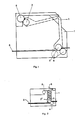
- a coil with an iron core 5 is arranged on one of the legs and a clamping element is arranged at a distance therefrom.
- this clamping member can be a pivotable clamping arm 2.
- a first magnetic rod 3 sits parallel to the coil with the iron core 5 in the clamping arm 2.
- the other leg of the frame 1 has a second magnetic rod 4 approximately opposite the joint of the clamping arm 2, which projects somewhat into the pivoting range of the clamping arm 2.
- the clamping arm 2 In the open position of the match stop device, the clamping arm 2 is attracted to the coil with an iron core.
- the fuse 8 slides along the other leg over the second magnetic rods 4.
- the coil with iron core 5 receives current and the magnetic field that builds up repels the first magnetic rod 3 mounted on the clamping arm 2. This reaches the area of attraction of the second magnetic bars 4 and is pulled against the second magnetic bar 4 projecting into the pivoting area of the clamping arm 2.
- the fuse between these two magnetic bars 3 and 4 is clamped and their further transport is prevented.
- the clamping arm 2 is reset by hand by the operator who is already manipulating the fuse or by an electrical or electromechanical reset device.
- FIG. 2 In another embodiment (FIG. 2) of a sliver stop device, a slide element 2 ′ guided in a slot is used instead of a clamping arm 2 as a carrier for the first magnetic rod 3.
- the magnetic rod 3 In the open position, the magnetic rod 3 is also back from the coil Iron core 5 tightened and held. If the thread breaks, the bobbin with iron core 5 receives current again and repels the first magnetic rod 3.
- the fuse 8 is clamped by the attraction of the second magnetic bars 4.
- the reset can be done by hand or by a reset device 6, e.g. B. a spring.
- the forces of attraction and repulsion can be metered very precisely. It is also possible to control the closing force as a function of pressure by providing a support for the clamping elements with a pressure sensor and regulating the closing force via a control device.
- the clamping elements which are formed by the first and second magnetic rods 3 and 4 in the first and second embodiment, can also carry cams or other elevations or a profile that enables a partially positive clamping, so that the clamping forces can be kept small. This can be particularly advantageous for certain materials.
- this sliver stop device lies in the easily accessible and free sliver path and in the very simple manufacture of the device. In some variants, the good and controllable clamping force is also essential.
Landscapes
- Engineering & Computer Science (AREA)
- Mechanical Engineering (AREA)
- Textile Engineering (AREA)
- Spinning Or Twisting Of Yarns (AREA)
Description
- Die Erfindung bezieht sich auf eine Lutenstopvorrichtung an Spinnmaschinen zum Unterbrechen des Luntentransportes bei Fadenbruch.
- Eine bekanntgewordene Luntenstopvorrichtung weist ein Stopsegment auf, welches die Form eines geschlitzten Hohlzylinders hat und auf je einen geriffelten Bereich einer einlaufseitigen Streckwalze gesteckt und vom Riffelteil dieser gehalten wird. Ein Hebelsystem, das in das Stopsegment eingreift, steht mit einem ausgangsseitig des Streckwerkes angeordneten Fadenfühler in Verbindung und wird von diesem gesteuert.
- Bei Fadenbruch ausgangsseitig des Streckwerkes wird das Stopsegment auf der Streckwalze ausgeklinkt und von der einlaufenden Lunte mitgenommen, bis sich das Stopsegment zwischen der Gegenwalze und der Streckwalze verklemmt und die zwischen diesen durchlaufende Lunte festgehalten und so durchtrennt wird.
- Eine andere bekanntgewordene Luntenstopvorrichtung weist ein Luntenführungsrohr auf, in dem die Lunte quer zu dessen Längsachse in einer Oeffnung geführt ist. Im Luntenführungsrohr befindet sich ein koaxialer, verschiebbarer Stempel, dessen Stellbewegung von einem fotoelektrischen Fadenwächter gesteuert wird.
- Reisst der gesponnene Faden, wird der Stempel im Luntenführungsrohr verschoben und die Lunte abgeschert. Die Luntenstopvorrichtung wird einlaufseitig auf dem Streckwerk montiert.
- Bei der ersten Vorrichtung ist der wesentlichste Nachteil, dass sie nicht auf Streckwerke verschiedener Geräte bzw. Fabrikate montiert werden kann. Die Masse des Stopsegmentes müssen sehr genau auf die vorgesehene Riffelwelle abgestimmt sein. Vor allem sind dies der Innendurchmesser im Bereich des Riffelzylinders, die Bundmasse beidseits des Riffelzylinders, die Länge zwischen den Bunden und der Keilwinkel des Stopsegmentes, welcher für einen funktionsgerechten Einzug desselben erforderlich ist.
- Ausserdem sind grossvolumige Steuergeräte und Hebelsysteme, auch bei der Verwendung elektronischer Sensoren, erforderlich.
- Auch die, zweite Ausführungsform einer Luntenstopvorrichtung benötigt sehr viel Raum, der im Bereich des Streckwerkes im allgemeinen nicht zur Verfügung steht.
- Durch die scherende Klemmung der Lunte in der Luntenstopvorrichtung kommt es zu Fusselbildung zwischen dem Luntenführungsrohr und dem in diesem gleitenden koaxialen Stempel, was die Wirkung der Luntenstopvorrichtung verschlechtert. Da die Lunte durch eine Oeffnung im Luntenführungsrohr eingeführt werden muss, erfordert das Einlegen der Lunte relativ viel Zeit und Geschicklichkeit.
- Ziel der Erfindung ist die Schaffung einer bedienungsfreundlichen, sehr wenig Platz beanspruchenden und nicht verschmutzungsgefährdeten Luntenstopvorrichtung, welche an Streckwerke verschiedener Konstruktionsarten ohne umfangreiche Adaptionsarbeiten angebaut werden kann.
- ' Dieses Ziel lässt sich erfindungsgemäss mit den Merkmalen nach dem kennzeichnenden Teil des Anspruchs 1 erreichen. Ausserdem kann die Luntenstopvorrichtung die Merkmale der Ansprüche 2 bis 12 aufweisen.
- Weitere Einzelheiten und Vorteile ergeben sich aus der Beschreibung zweier Ausführungsbeispiele der Erfindung anhand der Zeichnung.
- In dieser zeigt
- Figur 1 eine Seitenansicht der Luntenstopvorrichtung
- Figur 2 eine andere Ausführungsform einer Luntenstopvorrichtung.
- In einem C-förmigen Rahmen 1 ist an einem der Schenkel eine Spule mit Eisenkern 5 und in einem Abstand von dieser ein Klemmorgan angeordnet. Dieses Klemmorgan kann bei einer Ausführungsvariante (Fig.1) ein schwenkbarer Klemmarm 2 sein. An seinem freien Ende sitzt parallel zur Spule mit dem Eisenkern 5 im Klemmarm 2 ein erster Magnetstab 3.
- Der andere Schenkel des Rahmens 1 weist ungefähr gegenüber dem Gelenk des Klemmarms 2 einen zweiten Magnetstab 4 auf, wobei dieser etwas in den Schwenkbereich des Klemmarmes 2 ragt.
- Es ist aber auch möglich, mehrere zweite Magnetstäbe 4 parallel zueinander vorzusehen. Dabei ragt nur der letzte zweite Magnetstab 4 in den Schwenkbereich des Klemmarmes 2. Die zweiten Magnetstäbe 4 sind zum auf dem Klemmarm 2 angeordneten ersten Magnetstab 3 anziehend gepolt.
- In der Offenstellung der Luntenstopvorrichtung ist der Klemmarm 2 von der Spule mit Eisenkern angezogen. Die Lunte 8 gleitet entlang dem anderen Schenkel über die zweiten Magnetstäbe 4. Bei einem Fadenbruchsignal von einem Fadenwächter erhält die Spule mit Eisenkern 5 Strom und das sich aufbauende Magnetfeld stösst den auf dem Klemmarm 2 montierten ersten Magnetstab 3 ab. Dieser gelangt in den Anziehungsbereich der zweiten Magnetstäbe 4 und wird gegen den in den Schwenkbereich des Klemmarms 2 ragenden zweiten Magnetstab 4 gezogen. Die zwischen diesen beiden Magnetstäben 3 bzw. 4 liegende Lunte wird festgeklemmt und ihr Weitertransport unterbunden. Die Rückstellung des Klemmarmes 2 erfolgt von Hand durch die ohnehin mit der Lunte manipulierende Bedienungsperson oder durch eine elektrische oder elektromechanische Rückstelleinrichtung.
- Bei einer anderen Ausführungsform (Fig.2) einer Luntenstopvorrichtung wird anstelle eines Klemmarmes 2 als Träger für den ersten Magnetstab 3 ein in einem Schlitz geführtes Schlittenelement 2' verwendet. In der Offenstellung ist der Magnetstab 3 auch wieder von der Spule mit Eisenkern 5 angezogen und festgehalten. Bei Fadenbruch erhält die Spule mit Eisenkern 5 wieder Strom und stösst den ersten Magnetstab 3 ab. Durch die Anziehung von den zweiten Magnetstäben 4 wird die Lunte 8 festgeklemmt. Auch hier kann die Rückstellung von Hand oder durch eine Rückstelleinrichtung 6, z. B. eine Feder, erfolgen. Es ist bei beiden Ausführungsformen möglich, anstelle der ersten oder zweiten Magnetstäbe 3 bzw. 4, welche Permanentmagnete sind, Elektromagnete zu verwenden. Dadurch sind die Anziehungs- und Abstossungskräfte, also auch die Schliesskräfte, sehr genau dosierbar. Es ist auch möglich, die Schliesskraft druckabhängig zu steuern, indem ein Aufleger der Klemmelemente mit einem Druckfühler versehen wird und dieser über eine Regeleinrichtung die Schliesskraft regelt.
- Die Klemmelemente, welche bei der ersten und zweiten Ausführungsform durch die ersten und zweiten Magnetstäbe 3 bzw. 4 gebildet sind, können auch Nocken oder andere Erhebungen bzw. ein Profil tragen, das eine teilweise formschlüssige Klemmung ermöglicht, sodass die Klemmkräfte klein gehalten werden können. Dies kann insbesondere bei bestimmten Materialien von Vorteil sein.
- Der besondere Vorteil dieser Luntenstopvorrichtung liegt in der gut zugänglichen und freien Luntenbahn sowie in der sehr einfachen Herstellung der Vorrichtung. Bei einigen Varianten ist zusätzlich die gute und zeitlich steuerbare Klemmkraft wesentlich.
Claims (12)
Applications Claiming Priority (2)
| Application Number | Priority Date | Filing Date | Title |
|---|---|---|---|
| CH141/83 | 1983-01-12 | ||
| CH14183A CH660039A5 (de) | 1983-01-12 | 1983-01-12 | Luntenstopvorrichtung. |
Publications (2)
| Publication Number | Publication Date |
|---|---|
| EP0114568A1 EP0114568A1 (de) | 1984-08-01 |
| EP0114568B1 true EP0114568B1 (de) | 1986-05-28 |
Family
ID=4180180
Family Applications (1)
| Application Number | Title | Priority Date | Filing Date |
|---|---|---|---|
| EP19830810558 Expired EP0114568B1 (de) | 1983-01-12 | 1983-12-02 | Luntenstopvorrichtung |
Country Status (3)
| Country | Link |
|---|---|
| EP (1) | EP0114568B1 (de) |
| CH (1) | CH660039A5 (de) |
| DE (1) | DE3363821D1 (de) |
Families Citing this family (2)
| Publication number | Priority date | Publication date | Assignee | Title |
|---|---|---|---|---|
| DE19507266C1 (de) * | 1995-03-03 | 1996-10-10 | Chemnitzer Spinnereimaschinen | Luntenstopvorrichtung für Streckwerke an Spinnmaschinen |
| IT201800009797A1 (it) * | 2018-10-29 | 2020-04-29 | Fameccanicadata Spa | Dispositivo di intrappolamento per un filo |
Family Cites Families (4)
| Publication number | Priority date | Publication date | Assignee | Title |
|---|---|---|---|---|
| CH286065A (de) * | 1949-10-29 | 1952-10-15 | Perfogit S P A | Vorrichtung zum Abtrennen von Fäden, die in einer sie verarbeitenden Maschine, beispielsweise in einer Fadenstreckeinrichtung, gebrochen sind. |
| GB1154847A (en) * | 1965-07-16 | 1969-06-11 | Edmund Hamel | Improvements in Stop Motions for Spinning Frames and the like |
| NL7217621A (de) * | 1972-12-22 | 1974-06-25 | ||
| DE2619430C2 (de) * | 1976-05-03 | 1985-08-22 | W. Schlafhorst & Co, 4050 Mönchengladbach | Vorrichtung zur Überwachung des Fadenlaufs |
-
1983
- 1983-01-12 CH CH14183A patent/CH660039A5/de not_active IP Right Cessation
- 1983-12-02 EP EP19830810558 patent/EP0114568B1/de not_active Expired
- 1983-12-02 DE DE8383810558T patent/DE3363821D1/de not_active Expired
Also Published As
| Publication number | Publication date |
|---|---|
| EP0114568A1 (de) | 1984-08-01 |
| CH660039A5 (de) | 1987-03-13 |
| DE3363821D1 (en) | 1986-07-03 |
Similar Documents
| Publication | Publication Date | Title |
|---|---|---|
| DE3536913A1 (de) | Verfahren und vorrichtung zur steuerung einer luntenstop-anordnung einer spinnmaschine | |
| EP0114568B1 (de) | Luntenstopvorrichtung | |
| DE2111316B2 (de) | Vorrichtung zum Anspinnen gerissener Fäden in einer Spinnmaschine | |
| EP0322636B1 (de) | Stoppvorrichtung für ein Faserband an einer Textilmaschine | |
| DE3244669A1 (de) | Pneumatische fadenspleissvorrichtung zum spleissen kerngesponnener faeden | |
| DE1987810U (de) | Vorrichtung zur garnfuehrung bei der permanenten kraeuselung von textilgarnen. | |
| EP0344100A1 (de) | Elektromagnetische Einrichtung für Webmaschinen | |
| DE2041432C3 (de) | Garnklemme für Schußgarneintragsorgane an Webmaschinen | |
| DE2836717C3 (de) | Positive Fadenliefervorrichtung für Textilmaschinen | |
| EP2176156B1 (de) | Vorrichtung zum schneiden eines fadenförmigen körpers | |
| DE2711163A1 (de) | Offenend-spinnmaschine mit einer vielzahl von spinnaggregaten und wenigstens einem verfahrbaren wartungsgeraet | |
| DE2636845C2 (de) | OE-Spinnmaschine mit einer Vielzahl nebeneinander angeordneter Spinnaggregate | |
| DE2024110C3 (de) | Verfahren und Vorrichtung zur Überwachung der Vorbereitung von Spinnkopsen für den Abspulvorgang | |
| DE2438006C2 (de) | Fadenueberwachungsvorrichtung | |
| DE102021129446A1 (de) | Garnspanner, Arbeitsstelle sowie Verfahren zum Betreiben einer Arbeitsstelle | |
| CH699425B1 (de) | Vorrichtung zum Schneiden eines fadenförmigen Körpers. | |
| EP0276470B1 (de) | Vorrichtung zur Überwachung des Garnvorrates auf Garnspulen | |
| DE3838162A1 (de) | Verfahren zur abbremsung eines laufenden fadenartigen gebildes und fadenbremse zur durchfuehrung des verfahrens | |
| DE1735013A1 (de) | Verfahren und Vorrichtung zum Spinnen von Kerngarn | |
| DE879587C (de) | Elektrische Fadenwaechteranlage, insbesondere fuer Strickmaschinen | |
| DE3308068C1 (de) | Vorrichtung zum Einziehen von Materialbahnen in Rotationsdruckmaschinen | |
| DE4338057C2 (de) | Fadenstoppvorrichtung für Textilmaschinen | |
| DE275374C (de) | ||
| DE925516C (de) | Vorrichtung zum UEberwachen und Steuern von Textilmaschinen, insbesondere Spinnmaschinen, in Abhaengigkeit von Fadenbruechen | |
| AT255636B (de) | Vorrichtung zur Garnführung bei der permanenten Kräuselung von Textilgarnen |
Legal Events
| Date | Code | Title | Description |
|---|---|---|---|
| PUAI | Public reference made under article 153(3) epc to a published international application that has entered the european phase |
Free format text: ORIGINAL CODE: 0009012 |
|
| 17P | Request for examination filed |
Effective date: 19831206 |
|
| AK | Designated contracting states |
Designated state(s): BE DE FR IT SE |
|
| ITCL | It: translation for ep claims filed |
Representative=s name: MODIANO & ASSOCIATI S.R.L. |
|
| EL | Fr: translation of claims filed | ||
| GRAA | (expected) grant |
Free format text: ORIGINAL CODE: 0009210 |
|
| AK | Designated contracting states |
Kind code of ref document: B1 Designated state(s): BE DE FR IT SE |
|
| REF | Corresponds to: |
Ref document number: 3363821 Country of ref document: DE Date of ref document: 19860703 |
|
| ET | Fr: translation filed | ||
| ITF | It: translation for a ep patent filed | ||
| PLBE | No opposition filed within time limit |
Free format text: ORIGINAL CODE: 0009261 |
|
| STAA | Information on the status of an ep patent application or granted ep patent |
Free format text: STATUS: NO OPPOSITION FILED WITHIN TIME LIMIT |
|
| 26N | No opposition filed | ||
| PG25 | Lapsed in a contracting state [announced via postgrant information from national office to epo] |
Ref country code: SE Effective date: 19891203 |
|
| PGFP | Annual fee paid to national office [announced via postgrant information from national office to epo] |
Ref country code: FR Payment date: 19901129 Year of fee payment: 8 |
|
| PGFP | Annual fee paid to national office [announced via postgrant information from national office to epo] |
Ref country code: BE Payment date: 19901207 Year of fee payment: 8 |
|
| ITTA | It: last paid annual fee | ||
| PGFP | Annual fee paid to national office [announced via postgrant information from national office to epo] |
Ref country code: DE Payment date: 19910126 Year of fee payment: 8 |
|
| PG25 | Lapsed in a contracting state [announced via postgrant information from national office to epo] |
Ref country code: BE Effective date: 19911231 |
|
| BERE | Be: lapsed |
Owner name: GEBRUEDER LOEPFE A.G. Effective date: 19911231 |
|
| PG25 | Lapsed in a contracting state [announced via postgrant information from national office to epo] |
Ref country code: FR Effective date: 19920831 |
|
| PG25 | Lapsed in a contracting state [announced via postgrant information from national office to epo] |
Ref country code: DE Effective date: 19920901 |
|
| REG | Reference to a national code |
Ref country code: FR Ref legal event code: ST |
|
| EUG | Se: european patent has lapsed |
Ref document number: 83810558.3 Effective date: 19900830 |