EP0114645A2 - Sonde de température - Google Patents
Sonde de température Download PDFInfo
- Publication number
- EP0114645A2 EP0114645A2 EP84100438A EP84100438A EP0114645A2 EP 0114645 A2 EP0114645 A2 EP 0114645A2 EP 84100438 A EP84100438 A EP 84100438A EP 84100438 A EP84100438 A EP 84100438A EP 0114645 A2 EP0114645 A2 EP 0114645A2
- Authority
- EP
- European Patent Office
- Prior art keywords
- substance
- conductors
- temperature
- temperature sensor
- sensor according
- Prior art date
- Legal status (The legal status is an assumption and is not a legal conclusion. Google has not performed a legal analysis and makes no representation as to the accuracy of the status listed.)
- Withdrawn
Links
Images

Classifications
-
- H—ELECTRICITY
- H05—ELECTRIC TECHNIQUES NOT OTHERWISE PROVIDED FOR
- H05B—ELECTRIC HEATING; ELECTRIC LIGHT SOURCES NOT OTHERWISE PROVIDED FOR; CIRCUIT ARRANGEMENTS FOR ELECTRIC LIGHT SOURCES, IN GENERAL
- H05B3/00—Ohmic-resistance heating
- H05B3/40—Heating elements having the shape of rods or tubes
- H05B3/54—Heating elements having the shape of rods or tubes flexible
- H05B3/56—Heating cables
-
- G—PHYSICS
- G01—MEASURING; TESTING
- G01K—MEASURING TEMPERATURE; MEASURING QUANTITY OF HEAT; THERMALLY-SENSITIVE ELEMENTS NOT OTHERWISE PROVIDED FOR
- G01K7/00—Measuring temperature based on the use of electric or magnetic elements directly sensitive to heat ; Power supply therefor, e.g. using thermoelectric elements
- G01K7/16—Measuring temperature based on the use of electric or magnetic elements directly sensitive to heat ; Power supply therefor, e.g. using thermoelectric elements using resistive elements
- G01K7/26—Measuring temperature based on the use of electric or magnetic elements directly sensitive to heat ; Power supply therefor, e.g. using thermoelectric elements using resistive elements the element being an electrolyte
Definitions
- This invention relates to a temperature sensor.
- the invention is particularly, but not exclusively, pertinent to a thermostatic sensor which is operative to cut off or reduce the heating effect of a heat producing device when the sensor detects a temperature at or above a predetermined temperature, and which may be operative to restore the heating effect of the heat producing device when the sensor detects a temperature below the predetermined temperature.
- the invention has been primarily devised for use with an electrical heat producing device such as a heating tape to cut off or reduce the power supply to the heating tape when a temperature at or above the predetermined temperature is sensed, although the sensor may be used in many other applications, for example to restrict the supply of fuel to a heat producing device comprising a fuel burner, when the temperature detected is at or above the predetermined temperature or merely to give warning when the predetermined temperature has been reached.
- an electrical heat producing device such as a heating tape to cut off or reduce the power supply to the heating tape when a temperature at or above the predetermined temperature is sensed
- the sensor may be used in many other applications, for example to restrict the supply of fuel to a heat producing device comprising a fuel burner, when the temperature detected is at or above the predetermined temperature or merely to give warning when the predetermined temperature has been reached.
- a conductor In a heating tape, a conductor (or conductors) extends along the length of the tape. An electrical current is passed through the conductor and, due to the resistance of the conductor, heating occurs.
- Such heating tapes have many applications such as in preventing the freezing of chemicals in an exposed pipe or duct, around which such heating tape may be wound, or to maintain the temperature of a chemical as the chemical flows from one location to another along a pipe or duct.
- Another use is to heat a chemical, in a container around which the tape is wound, to a specific temperature.
- the temperature it would be preferred for the temperature to be monitored along the entire length of the tape without having to provide a large number of temperature monitors.
- a temperature sensor comprising first and second electrical conductors, a substance in electrical contact with each of the conductors, said substance having a significantly different electrical resistivity when the substance is at a temperature below a transition temperature range than when the substance is at a temperature above said transition temperature range.
- the difference in electrical resistivity of the substance can be sensed by any known means, e.g. electrically to produce a signal to provide an indication that the substance is at a predetermined temperature within said transition temperature range, or alternatively to produce a control signal to control the heating effect of a heat producing device in dependance upon the temperature of the substance, or for any other purpose.
- the electrical sensing means can sense a small change in resistance between the conductors
- a substance can be selected the resistance of which only changes by a small amount within said range.
- the electrical sensing means can only detect larger changes in resistivity, a substance having a more marked change in resistivity wjthin said transition temperature range would need to be selected.
- the conductors may be connected to a control circuit which is operable to sense said change in resistivity between the two conductors and to provide a control signal to a controllable heat producing device in response to the change in resistivity and hence in response to the temperature of the substance.
- a resistance i.e. a resistor is connected in series between the control circuit and a conductor to limit the current flowing from one conductor to the other to avoid the risk of decomposing said substance.
- the resistor may have a numerical value equal to between eight and fifteen times the working voltage in volts e.g. if the working voltage is 240V, then the resistance preferably has a value between 1920 ohms and 3600 ohms.
- one of the conductors carries a control voltage
- the other conductor may be connected to earth, via an earth current leakage circuit breaker arranged to provide said indicating or control signal when a current passing to earth from said other conductor is detected.
- the heat producing device may be an electrical heating means, and the signal from the circuit breaker may be arranged to control the power supply to the heating means.
- the heat producing device may be non-electrically powered, and the signal from the circuit breaker may be arranged to control a fuel supply to the heating means.
- the substance may be impregnated in or provided on an electrically non-conductive material, such as a woven glass fibrous material, by which at least one of the conductors is surrounded.
- At least one of the conductors may have an electrically non-conducting thread, such as a glass fibre thread, wound therearound, for example helically, the spaces between the windings having substance therein.
- the other conductor may be wound around said one conductor with the thread serving as a spacer and the substance being in electrical contact with both said conductors.
- the thread provides an insulating barrier between the conductors, at least below the transition temperature range.
- a further thread may be wound around the assembly to bind the conductors together and the assembly may be embedded in a further substance or a different substance.
- first and second conductors may extend in parallel spaced relationship with the electrically non-conducting thread, such as a glass fibre thread, the substance being provided on or in the non-conductive thread to provide a current path between the conductors at least when the substance is more electrically conductive.
- the electrically non-conducting thread such as a glass fibre thread
- the first and second conductors may comprise elongate elements which extend from one location to another as in a heating tape.
- conductors are elongate conductive elements, they may be flat and comprise foil elements, or may be round or oval or any other desired cross section.
- the conductors may comprise sotid or multi-strand core wires, or braided wires.
- the first and second conductors are parallel to one another or at least equally constantly spaced so that the resistance between the conductors, at a given temperature, is constant over the entire length or area of the conductors.
- the conductors may be arranged in a lattice over the area but preferably in this case, the conductors comprise lamini conductive elements which extend over substantially the entire area with said substance therebetween.
- the upper and lower temperatures of the transition temperature range will vary depending upon the substance.
- the extent of the transition temperature range i.e. the difference between the upper and lower temperatures, will also vary depending upon the substance. In the majority of suitable substances the change in resistivity will take place in a transition temperature range of limited extent. The range may be within 20°C. For other substances, the change in resistivity may occur over a temperature range of zero or nearly zero.
- the term "temperature range” is intended to cover a case where the extent of the range is zero, i.e. where the upper and lower temperatures of the range are identical, as well as ranges up to a difference between the upper and lower temperatures of 30°C.
- the substance undergoes a change of state between the limits of the transition temperature range.
- the substance may be solid at a temperature below the transition temperature range, and be molten when at a temperature above the transition temperature range.
- the sensing means may be arranged to provide a signal in response to a predetermined temperature being sensed.
- the sensing means may be arranged to provide a signal which varies in response to a change in temperature within the range. For example, on a rising temperature the signal may be provided at the lower end of the range, at some predetermined temperature within the range or at the upper end of the range, depending, of course, on the sensitivity of the sensing means.
- the substance is preferably a salt or a mixture of salts.
- a salt which is ionic
- the positive and negative ions when the salt is in a solid state, are held in a molecular lattice and thus are not free to move.
- the salt behaves as an insulator.
- the ions when the salt is in a molten state, the ions are free to move and the salt behaves as a conductor.
- the conduction may increase significantly as the salt temperature approaches the melting point or temperature range where melting occurs over a range of temperatures.
- the substance may comprise a single type of salt where, for example the salt melts in the required transition temperature range.
- the substance may comprise a mixture of salts or other compounds to achieve melting in a desired transition temperature range.
- Salts have been found to be particularly suitable for this use because they give a sharp increase in conductivity over the transition temperature range, although other suitable substances may be used.
- the salt or salts may comprise a group I salt or salts such as one of, or a mixture of more than one of the following namely :
- the electrically non-conductive material and conductors may be dipped into a salt solution such as a .15% solution of the desired salt or salts, and then the material permitted to dry so that the salt ions remain impregnated in and on the conductors/material whilst the water evaporates.
- a salt solution such as a .15% solution of the desired salt or salts
- the substance may comprise a powder impregnated on the woven material, or the substance may be impregnated by melting the substance and dipping the material into the molten salt.
- the type of salt or other substance used, the distance between the conductors and the strength of the solution may be chosen empirically to provide a suitable sensor for a particular use.
- the magnitude of the voltage may affect the performance of the sensor. For example, where a high voltage is passed through the conductor, current leakage through the substance below the predetermined transition temperature range may increase, Thus the control voltage needs to be selected with regard to the other factors mentioned, to achieve a suitable sensor.
- control voltage may comprise a mains voltage, whereby it is unnecessary to provide any expensive transformer or the like to achieve a lower voltage for sensing purposes.
- the current may be direct or alternating but particularly where mains voltage is used, it is of course more convenient to use an alternating current.
- the invention is- particularly applicable as a thermostatic sensor to control the heating effect of a heating tape or sheet by providing the sensor in association with the heating tape or sheet which may comprise an outer covering containing one or more elongate heating conductors, such as foils or wires through which, in use, as an-electrical current is passed, the conductors having a sufficiently high resistance that heating of the conductors occurs, to sense the temperature of the heating tape or sheet or article heated thereby.
- the conductors may be embedded in a non-conductive material such as fibreglass and/or covered by a rubber material
- the thermostatic sensor may also be contained within the outer covering.
- the conductors of the sensor may comprise also two heating conductors of the heating tape or sheet.
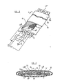
- a heating tape 10 comprises four elongate conductors I arranged in two pairs which are adapted to carry an electrical current and are connected as illustrated diagrammatically, at one end 12, to a power source 13, one pair being connected through a relay 14, or solid state switch, the other ends of the conductors (11 being mutually interconnected by a further conductor 11a so that the current flows from one of the conductors I of each pair to the other.
- the conductors I are thin and provide a high resistance to the flowing current, thus causing heating of the conductors I and hence of the tape 10.
- the conductors I are arranged in individual pockets 15 of a non-conductive, woven, glass fibrous material 15a which extends longitudinally of the tape and maintains the spacing between the conductors, without any risk of short circuit, whilst permitting flexibility of the tape.
- the temperature sensor 16 comprises a pair of conductors 20a and 20b also received in individual pockets 25 of a further inner tape 26 of the sensor 16, which tape 26 is again made from a woven glass fibre material but could be made from an alternative material.
- tape 26 is not entirely insulated, in that the tape 26 is impregnated with a substance, as hereinafter described, which is solid and non-conducting or substantially non-conducting below a transition temperature range, and molten- and conducting at a temperature above the transition temperature range.
- the temperature sensor 16 can be used to control the heating effect of the tape 10 as follows.
- One of the conductors 20b is connected to earth, via a resistor R in series with an earth leakage detector 27 which, when a current is detected in conductor 20b provides a control signal to the relay 14 to switch off the power supply to the conductors 11.
- the other conductor 20a is connected to the power supply 13 or alternatively to a lower power source as required.
- the earth leakage detector 27 and relay 14 together comprise an ear h leakage circuit breaker 28.
- the resistor R limits the current to the earth leakage circuit breaker 28 and has a numerical value in ohms of betweer. eight and fifteen times the working voltage, in volts.
- an indicating means such as that shown at I, may be provided to indicate that a temperature above a predetermined temperature within the transtion temperature range, has been attained.
- the woven glass fibre material 26 is impregnated with a substance.
- Preferred substances are salts which may be impregnated by preparing a solution of the salt, for example a 15% solution, and dipping the tape 26, with the conductors 20a, 20b embedded therein, in the solution and then permitting the material to dry.
- the material 26 could be dipped in molten substance or powder could be impregnated into the material.
- a salt is chosen which has a significant decrease in resistivity in a selected transition temperature range.
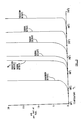
- transition temperature range the lower limit of which is about 210 0 C
- there is very little current permitted to flow through the sodium chlorate indicating a high resistivity.
- the upper limit of the transition temperature range i.e. about 250°C, current is permitted to flow freely.
- the earth leakage circuit breaker 28 is arranged to detect only a current above the small current which can flow when the substance is below the lower limit of the transition temperature range.
- the sensing means may detect a decrease in resistivity which occurs at the lower end of the transition range, or at any temperature within the range.
- the melting point of sodium chlorate is 255 v C. It can be seen from Figure 3 that due to the current flowing In conductors 20 a, 20b that the salt conducts below this melting temperature. Generally, the higher the control voltage, the lower the temperature at which the salt conducts. This is also dependant on the distance between the conductors 20a and 20b and the amount of substance, i.e. the density of substance between the conductors.
- the graphs are only intended to show the characteristic increase of current flow over a transition temperature range which is near the melting point. Although the graph only shows currents up to 20 mA, it will be appreciated that much higher currents can flow.
- Other salts of course have different melting points and may alternatively be used where the melting point is close to the predetermined temperature within the transition temperature range, which it is designed to detect.
- the conductors 11, woven glass fibre insulating material 15c and the thermostatic sensor 16 are all encased in a rubber, plastic or other suitable non-conductive prptective casing 30 which again permits flexing of the tapes 10 and 26 whilst providing protection against adverse environmental conditions.
- the conductors 20a, 20b and 1 are each received in individual pockets in a woven glass fibre material, it will be appreciated that any other suitable non-conductive material, or material which can be impregnated with substance, could be used.
- the invention is not limited to heating tapes as described.
- a temperature sensor such as sensor 16 may be used to control the temperature of a heating plate, in which case the conductors 20a and 20b and the substance impregnated in the tape 26 may be arranged in a lattice over the entire hot plate.
- the conductors instead of the conductors being elongate conductive elements as shown, the conductors may themselves comprise lamini elements between which the substance is located.
- control signal could be derived from a temperature sensor such as sensor 16 and used to cut off or reduce the supply of fuel to a fuel burner or any other heat producing device.
- the sensor 16 has wider application as a thermostatic sensor not. only to control the heating effect of any heating means, but also to provide a temperature dependant signal for any purpose.
- thermostatic sensor 16 may be used to merely detect a temperature at above or below a predetermined temperature.
- the sensor may be connected in a control circuit, or earth leakage circuit breaker as described above to merely give an indication or warning such as an alarm or visual indication that a predetermined temperature within the transition temperature range has been reached, or exceeded or fallen below.
- the substance need not be impregnated in or on a woven material as described, but could be a powder or solid surrounding the conductors, such as described below with reference to Figure 4.
- control voltage as low as 50 volts (or lower) may be used.
- FIG. 4 there is shown a second embodiment of the invention comprising a temperature sensor 36.
- the sensor 36 is not shown incorporated into a heating tape 10 as hereinbefore described, but may if required be used in place of sensor 16, or in any other type of heating tape, or in any other application where it is desired to monitor a temperature and/or control a heating means.
- the sensor 36 has a pair of conductors 37, 38 corresponding to conductors 20a, 20b of the embodiment shown in Figures I and 2, in the present case the conductor 38 being thinner than the conductor 37, although they could be of the same size, and the conductor 38 is spirally wound around the conductor 37 but they are spaced from one another as hereinafter described.
- the conductors 37, 38 each comprise a multi-strand wire for flexibility, so that the sensor 36 can be wrapped around a pipe for example, if required, although alternatively one or both of the conductors could be solid, or even braided.
- Helically wound around conductor 37 is a glass fibre thread 39.
- deposits 41 of substance such as a salt as discussed above in connection with the Figures I and 2 embodiment.
- the substance may be deposited by dipping the conductor 37 and thread 39 into a solution of the substance cnd then permitting the water of the solution to evaporate off, or may be otherwise impregnated.
- the deposits 41 are only shown in outline and not in section, for clarity of the drawing.
- the second conductor 38 is bound to the conductor 37 and thread 39 assembly by a further glass fibre thread 40, the spacing between conductors 37 and 38 being maintained constant over the length of the sensor 36 by the thread 39.
- the whole assembly of conductors 37, 38 and threads 39 and 40 is then dipped into the solution of substance and dried as before, to leave a further deposit 42 of substance surrounding the conductors and threads. Again only the outline of deposits 42 is shown.
- the conductor 37 remains insulated from conductor 38 by virtue of thread 39 and the deposits of substance, at least when the substance is below the lower limit of the transition temperature range.
- the substance is a salt
- the substance is substantially more conducting.
- the lower limit, or a temperature within the range may be the same as the melting point of the salt.
- any other substance may be used as described in connection with the embodiment of Figures I and 2.
- the conductors 37 and 38 may be connected to a control circuit, similar to that described with reference to Figures I and 2, or any other control circuit as required to sense the decrease in restisivity of the substance and to provide an indication or warning signal when a temperature within the transition temperature range is sensed.
- the thread 39 need not be helically wound about the conductor 37 as described, but alternatively a sheath of glass fibre impregnated with a salt or other substance could be used.
- the senor 36 can extend along the entire length of the heating tape such as that shown at 10 in Figures I and 2, or could extend over only a short distance, to detect a temperature in a localised area.
- any other non-conducting material which can maintain the spacing between conductors 37 and 38 and retain deposits of substance could be used.
- a third embodiment of the invention comprising a temperature sensor 50 which may be used in a similar manner to the sensor 36.
- the sensor has a pair of parallel conductors 51, 52 each comprising a multi-strand wire for flexibility and maintained in spaced parallel relationship by glassfibre or other non- inflammable, non-electrically conductive threads 53 disposed between the conductors.
- the conductors 51, 52 and sensors 53 are secured together by a helically wound thread 54, again of glassfibre or other suitable material as discussed with reference to the Figure 4 embodiment.
- a heating tape 60 comprises a pair of spaced parallel elongate electrical conductors 61, 62 of high resistance so as to act as heating conductors in conventional manner.
- the conductors 61, 62 are surrounded by a non-conductive woven glassfibre material 63 which extends longitudinally. of the tape and maintains the spacing between the conductors.
- the tape is provided with a conventional outer protective covering 64.
- the glassfibre material 63 is impregnated with a substance as described hereinbefore so as to be solid and non-conducting or substantially non-conducting below a predetermined transition temperature range and melting and conducting at a temperature above the predetermined transition temperature range. Suitable electrical circuitry would need to be provided to sense a short circuit when the resistivity of the substance decreases.
- FIG 7 shows yet another embodiment in which a temperature sensor comprising a pair of elongate foil conductors 71, 72, each of which are 1/8 inch (3.17mm) wide and 0.002 inch (0.06mm) thick.
- the foils 71, 72 are separated by a woven glass fibre cloth 73 which is impregnated with substance as described with reference to the other embodiments described above.
- the assembly is sewn into a glass fibre tube 74 and/or if required placed in a protective rubber or other outer casing.
- This sensor could be used instead of the sensor 16 of the Figures and 2 embodiments.
Landscapes
- Chemical & Material Sciences (AREA)
- Chemical Kinetics & Catalysis (AREA)
- Electrochemistry (AREA)
- Physics & Mathematics (AREA)
- General Physics & Mathematics (AREA)
- Control Of Resistance Heating (AREA)
- Resistance Heating (AREA)
Applications Claiming Priority (2)
| Application Number | Priority Date | Filing Date | Title |
|---|---|---|---|
| GB838301666A GB8301666D0 (en) | 1983-01-21 | 1983-01-21 | Temperature sensor |
| GB8301666 | 1983-01-21 |
Publications (2)
| Publication Number | Publication Date |
|---|---|
| EP0114645A2 true EP0114645A2 (fr) | 1984-08-01 |
| EP0114645A3 EP0114645A3 (fr) | 1984-08-15 |
Family
ID=10536694
Family Applications (1)
| Application Number | Title | Priority Date | Filing Date |
|---|---|---|---|
| EP84100438A Withdrawn EP0114645A3 (fr) | 1983-01-21 | 1984-01-17 | Sonde de température |
Country Status (4)
| Country | Link |
|---|---|
| US (1) | US4565455A (fr) |
| EP (1) | EP0114645A3 (fr) |
| CA (1) | CA1206018A (fr) |
| GB (2) | GB8301666D0 (fr) |
Cited By (1)
| Publication number | Priority date | Publication date | Assignee | Title |
|---|---|---|---|---|
| CN102244948A (zh) * | 2010-05-12 | 2011-11-16 | 上海宝钢化工有限公司 | 一种伴热带的安装方法 |
Families Citing this family (11)
| Publication number | Priority date | Publication date | Assignee | Title |
|---|---|---|---|---|
| GB2179748B (en) * | 1985-08-20 | 1989-09-06 | Sharp Kk | Thermal flow sensor |
| JP2797736B2 (ja) * | 1991-02-21 | 1998-09-17 | キヤノン株式会社 | 定着装置 |
| IT1250833B (it) * | 1991-07-31 | 1995-04-21 | Fiat Auto Spa | Dispositivo rilevatore per valutare le condizioni di conforto termico in un ambiente, ad esempio nell'abitacolo di un autoveicolo. |
| US5493101A (en) * | 1993-12-15 | 1996-02-20 | Eaton Corporation | Positive temperature coefficient transition sensor |
| US5831511A (en) * | 1996-07-11 | 1998-11-03 | General Electric Co. | Resistance temperature detector assembly and method of fabricating same |
| AU4737501A (en) * | 2000-03-10 | 2001-09-24 | Univ North Carolina State | Method and system for conservative evaluation, validation and monitoring of thermal processing |
| US6839212B2 (en) | 2001-06-13 | 2005-01-04 | Eaton Corporation | Bus bar thermal detection |
| WO2004067786A2 (fr) * | 2003-01-28 | 2004-08-12 | North Carolina State University | Procedes, systemes et dispositifs pour evaluer un traitement thermique |
| EP2336757B1 (fr) * | 2009-12-07 | 2018-09-19 | ams international AG | Circuit intégré avec ensemble de détection de présence d'eau et son procédé de fabrication |
| EP2336756A1 (fr) * | 2009-12-15 | 2011-06-22 | Nxp B.V. | Capteur d'immersion de liquide |
| US20110214490A1 (en) * | 2010-03-02 | 2011-09-08 | Masami Sakita | Water leak detector |
Family Cites Families (19)
| Publication number | Priority date | Publication date | Assignee | Title |
|---|---|---|---|---|
| US2360434A (en) * | 1943-07-29 | 1944-10-17 | Dennis J Manning | Leak-locating apparatus |
| JPS324085B1 (fr) * | 1953-10-08 | 1957-06-22 | ||
| GB953165A (en) * | 1959-05-01 | 1964-03-25 | Graviner Manufacturing Co | Improvements in or relating to temperature sensitive devices |
| US3200388A (en) * | 1960-08-12 | 1965-08-10 | Weber Aircraft Corp | Water leakage alarm system |
| GB1048004A (en) * | 1962-06-15 | 1966-11-09 | Graviner Manufacturing Co | Improvements in temperature change detectors and method of manufacture thereof |
| GB1190671A (en) * | 1968-01-22 | 1970-05-06 | Kiyoichi Nijo | Temperature Detecting Apparatus. |
| DE1918419A1 (de) * | 1969-04-11 | 1970-10-15 | Stotz Kontakt Gmbh | UEberwachungsanordnung fuer die elektrische Beheizung von Instrumenten,Leitungen u.dgl. in OElraffinerien |
| AT309851B (de) * | 1969-11-04 | 1973-09-10 | Thermo Bauelement Ag | Temperaturschalter |
| FR2108275A5 (fr) * | 1970-09-30 | 1972-05-19 | Agfa Gevaert Ag | |
| GB1320251A (en) * | 1971-05-20 | 1973-06-13 | Findlay Irvine Ltd | Apparatus for providing an indication of the imminence of ice- formation |
| US3947656A (en) * | 1974-08-26 | 1976-03-30 | Fast Heat Element Manufacturing Co., Inc. | Temperature controlled cartridge heater |
| US4177376A (en) * | 1974-09-27 | 1979-12-04 | Raychem Corporation | Layered self-regulating heating article |
| US4246468A (en) * | 1978-01-30 | 1981-01-20 | Raychem Corporation | Electrical devices containing PTC elements |
| GB1595314A (en) * | 1978-05-08 | 1981-08-12 | Spill Fire Alarm Systems Ltd | Temperature monitoring devices |
| DE2913279C2 (de) * | 1979-04-03 | 1983-03-17 | Licentia Patent-Verwaltungs-Gmbh, 6000 Frankfurt | Elektrischer Widerstands-Temperaturfühler |
| FR2456453A1 (fr) * | 1979-05-10 | 1980-12-05 | Sunbeam Corp | Element chauffant flexible et son procede de fabrication |
| SE424359B (sv) * | 1979-09-05 | 1982-07-12 | Blom H | Anordning for brottindikering vid fjerrvermeror |
| US4315141A (en) * | 1980-09-05 | 1982-02-09 | Fieldcrest Mills, Inc. | Electrical heating apparatus with overheating protection |
| PL138268B1 (en) * | 1982-08-13 | 1986-08-30 | Politechnika Warszawska | Linear fire detector of warning fire protection system |
-
1983
- 1983-01-21 GB GB838301666A patent/GB8301666D0/en active Pending
-
1984
- 1984-01-12 GB GB08400770A patent/GB2134658B/en not_active Expired
- 1984-01-17 EP EP84100438A patent/EP0114645A3/fr not_active Withdrawn
- 1984-01-20 CA CA000445794A patent/CA1206018A/fr not_active Expired
- 1984-01-23 US US06/573,008 patent/US4565455A/en not_active Expired - Fee Related
Cited By (2)
| Publication number | Priority date | Publication date | Assignee | Title |
|---|---|---|---|---|
| CN102244948A (zh) * | 2010-05-12 | 2011-11-16 | 上海宝钢化工有限公司 | 一种伴热带的安装方法 |
| CN102244948B (zh) * | 2010-05-12 | 2013-02-13 | 上海宝钢化工有限公司 | 一种伴热带的安装方法 |
Also Published As
| Publication number | Publication date |
|---|---|
| US4565455A (en) | 1986-01-21 |
| CA1206018A (fr) | 1986-06-17 |
| GB2134658B (en) | 1987-05-13 |
| GB2134658A (en) | 1984-08-15 |
| GB8400770D0 (en) | 1984-02-15 |
| GB8301666D0 (en) | 1983-02-23 |
| EP0114645A3 (fr) | 1984-08-15 |
Similar Documents
| Publication | Publication Date | Title |
|---|---|---|
| EP0476637B1 (fr) | Câble chauffant de type zone commandé par commutateur et procédé | |
| US4503322A (en) | Heat sensitive heater wire | |
| US4577094A (en) | Electrical heating apparatus protected against an overheating condition | |
| US4607154A (en) | Electrical heating apparatus protected against an overheating condition and a temperature sensitive electrical sensor for use therewith | |
| EP0114645A2 (fr) | Sonde de température | |
| US4246468A (en) | Electrical devices containing PTC elements | |
| US4309596A (en) | Flexible self-limiting heating cable | |
| EP0202896B1 (fr) | Elément chauffant électrique en forme de feuille | |
| US4314145A (en) | Electrical devices containing PTC elements | |
| DK228483A (da) | Varmeelement | |
| US4891500A (en) | Self-healing parallel heating tape | |
| EP1645167B2 (fr) | Couverture chauffante | |
| WO1991014352A1 (fr) | Element de chauffage electrique destine a etre utilise dans un appareil de confort a usage personnel | |
| EP0092406A2 (fr) | Dispositif allongé de chauffage électrique et assemblage de tels dispositifs | |
| US5101190A (en) | Non-metal high resistance electric cable | |
| CA2098154C (fr) | Cable chauffant | |
| JPH0684587A (ja) | 感熱ヒータ | |
| JPS6248173B2 (fr) | ||
| GB2384631A (en) | An electric heating cable having a meltdown layer applied to a linear conductive core and a heating element spirally wound along the meltdown layer | |
| GB2138254A (en) | Heating device | |
| CA1187309A (fr) | Dispositif electrique comprenant un element a coefficient de temperature positif | |
| KR930024026A (ko) | 전선형 도전성 고분자의 열처리 방법 및 장치 |
Legal Events
| Date | Code | Title | Description |
|---|---|---|---|
| PUAI | Public reference made under article 153(3) epc to a published international application that has entered the european phase |
Free format text: ORIGINAL CODE: 0009012 |
|
| PUAL | Search report despatched |
Free format text: ORIGINAL CODE: 0009013 |
|
| AK | Designated contracting states |
Designated state(s): AT BE CH DE FR GB IT LI LU NL SE |
|
| AK | Designated contracting states |
Designated state(s): AT BE CH DE FR GB IT LI LU NL SE |
|
| 17P | Request for examination filed |
Effective date: 19850215 |
|
| 17Q | First examination report despatched |
Effective date: 19860526 |
|
| D17Q | First examination report despatched (deleted) | ||
| STAA | Information on the status of an ep patent application or granted ep patent |
Free format text: STATUS: THE APPLICATION IS DEEMED TO BE WITHDRAWN |
|
| 18D | Application deemed to be withdrawn |
Effective date: 19870630 |
|
| RIN1 | Information on inventor provided before grant (corrected) |
Inventor name: BLOORE, FREDERICK WILLIAM Inventor name: SEAMAN, PETER HERBERT |