EP0114799A2 - Apparatus for producing stamped sections in continuously advanced strip blank - Google Patents
Apparatus for producing stamped sections in continuously advanced strip blank Download PDFInfo
- Publication number
- EP0114799A2 EP0114799A2 EP84850021A EP84850021A EP0114799A2 EP 0114799 A2 EP0114799 A2 EP 0114799A2 EP 84850021 A EP84850021 A EP 84850021A EP 84850021 A EP84850021 A EP 84850021A EP 0114799 A2 EP0114799 A2 EP 0114799A2
- Authority
- EP
- European Patent Office
- Prior art keywords
- strip
- shaft
- stamping
- stamping tool
- tool
- Prior art date
- Legal status (The legal status is an assumption and is not a legal conclusion. Google has not performed a legal analysis and makes no representation as to the accuracy of the status listed.)
- Granted
Links
Images
Classifications
-
- B—PERFORMING OPERATIONS; TRANSPORTING
- B21—MECHANICAL METAL-WORKING WITHOUT ESSENTIALLY REMOVING MATERIAL; PUNCHING METAL
- B21D—WORKING OR PROCESSING OF SHEET METAL OR METAL TUBES, RODS OR PROFILES WITHOUT ESSENTIALLY REMOVING MATERIAL; PUNCHING METAL
- B21D53/00—Making other particular articles
- B21D53/24—Making other particular articles nuts or like thread-engaging members
-
- B—PERFORMING OPERATIONS; TRANSPORTING
- B21—MECHANICAL METAL-WORKING WITHOUT ESSENTIALLY REMOVING MATERIAL; PUNCHING METAL
- B21D—WORKING OR PROCESSING OF SHEET METAL OR METAL TUBES, RODS OR PROFILES WITHOUT ESSENTIALLY REMOVING MATERIAL; PUNCHING METAL
- B21D53/00—Making other particular articles
- B21D53/36—Making other particular articles clips, clamps, or like fastening or attaching devices, e.g. for electric installation
-
- B—PERFORMING OPERATIONS; TRANSPORTING
- B21—MECHANICAL METAL-WORKING WITHOUT ESSENTIALLY REMOVING MATERIAL; PUNCHING METAL
- B21H—MAKING PARTICULAR METAL OBJECTS BY ROLLING, e.g. SCREWS, WHEELS, RINGS, BARRELS, BALLS
- B21H8/00—Rolling metal of indefinite length in repetitive shapes specially designed for the manufacture of particular objects, e.g. checkered sheets
Definitions
- the present invention concerns an apparatus for producing stamped sections in a strip blank which is advanced continuously lengthwise past a stamping tool positioned to one side of the strip and arranged to cooperate with a support roll.
- the support roll is mounted on a shaft positioned on the side of the strip opposite the stamping tool in parallel with the plane of the strip and perpendicularly to the direction of advancement of the strip.
- Stamping operations of the kind defined above are used for instance to produce threads in the strip of hose clamps of the type wherein the strip passes through a screw-worm sleeve in engagement with a screw-worm positioned therein.
- the threads are usually produced through stamping in a large eccentric-shaft press which in a single operation forms all the thread grooves in a section of the strip.
- the stamped section is subsequently severed off the strip blank and shaped into the strip of the hose clamp.
- some flow of material occurs transversely relative to the lengthwise extension of the strip. This material flow increases the width of the strip by approximately 5%, with the result that the screw-worm sleeve tolerances need to be comparatively large.
- the difference in width between stamped and unstamped sections of the continuously advanced strip blank also is disadvantageous in that it makes it complicated to guide the strip, causes increased wear on the tools as well as operational disturbances.
- the purpose of the present invention is to effect the stamping of the strip blank without causing noticeable differences in width between the stamped and unstamped sections of the strip blank while at the same time making it possible to effect the stamping at a high rate of production.
- the apparatus in accordance with the invention is characterised in that the shaft is arranged to be turned between two end positions and in that the support roll is eccentrically mounted on the shaft and arranged by turning said shaft to one of the end positions, to urge the strip against the stamping tool and, by turning the shaft to the opposite end position thereof, to allow the strip to pass past the stamping tool out of contact with the latter.
- a strip blank 1 which is to be stamped along its length with thread-groove, sections and which in a subsequent operation is to be severed and shaped into a hose clamp strip, is continuously advanced by a pair of rollers 2 past a support roll 3.
- the support roll 3 is mounted on an eccentric shaft 4 which is positioned in parallel with the plane of the strip and perpendicularly to the direction of advancement of the latter.
- a stamping tool 5 the stamping face of which is formed to give the desired thread profiles is positioned on the opposite side of the strip 1 and is attached to a slide member 6 which is mounted for displacement in a plane which is essentially parallel to the plane of advancement of the strip.
- a bracket 7 mounted on the slide member 6 supports the piston rod of a piston-and-cylinder unit 8 arranged to displace the slide member to and fro.
- a second piston-and-cylinder unit 9 is secured to the eccentric shaft 4 via a lever.10. When the shaft 4 is turned with the aid of the lever 10 and the piston-and-cylinder unit 9 the support roll 3 may be.displaced transversely relative to the direction of advancement of the strip 1 towards or away from the stamping tool 5 between two end positions.
- the support roll 3 presses the strip 1 hard against the stamp tool 5.
- the slide member 6 is displaced by the piston-and-cylinder unit 8 in synchrony with the advancement of the strip by the pair of rollers 2, the stamping action being effected in the press nip between the support roll 3 and the stamping tool 5.
- the second piston-and-cylinder unit 9 When one thread section has been stamped, which is sensed by means provided to sense the movements of the slide member 6, by a time relay or by means arranged to sense the advancement of the strip, the second piston-and-cylinder unit 9 is activated, which by turning the shaft 4 in the opposite direction effects displacement of the support roll 3 away from the stamping tool 5. As a result the strip 1 is no longer pressed against the stamping tool and the tool is allowed to complete its movement forwards out of contact with the strip 1. The stamping tool is then brought back to its original position by the piston-and-cylinder unit 8 to effect another stamping operation.
- the strip 1 is advanced continuously at a constant rate and when one strip section having a length corresponding to the desired gap between two threaded sections has moved past by the support roll 3 the piston--and-cylinder unit 9 is again activated and serves to press the support roll against the stamping tool 5 to effect another stamping operation.
- the length of the stamped sections and the length of the unstamped sections separating them are easily varied by controlling the operation of the piston-and--cylinder 9 in such a manner that the support roll 3 when abutting against the stamping tool at one end position of the stamping tool provides the desired length of the stamped section whereas the desired interruption between the stamped sections is effected in the other end position.
- the invention is not limited to the embodiment described in the aforegoing but modifications thereof are possible within the scope of the appended claims.
- the means for advancement of the stamping tool 5, for example, are not essential, it being possible to shape the tool as a round stamping cylinder mounted on a shaft which is driven in synchrony with the speed of advancement of the strip.
- Other means than piston-and-cylinder units may be used to effect the movements of the slide member 6 and to operate the shaft 4.
Landscapes
- Engineering & Computer Science (AREA)
- Mechanical Engineering (AREA)
- Press Drives And Press Lines (AREA)
- Package Closures (AREA)
- Auxiliary Devices For And Details Of Packaging Control (AREA)
- Perforating, Stamping-Out Or Severing By Means Other Than Cutting (AREA)
- Tyre Moulding (AREA)
- Making Paper Articles (AREA)
- Machines For Manufacturing Corrugated Board In Mechanical Paper-Making Processes (AREA)
- Casting Or Compression Moulding Of Plastics Or The Like (AREA)
Abstract

Description
- The present invention concerns an apparatus for producing stamped sections in a strip blank which is advanced continuously lengthwise past a stamping tool positioned to one side of the strip and arranged to cooperate with a support roll. The support roll is mounted on a shaft positioned on the side of the strip opposite the stamping tool in parallel with the plane of the strip and perpendicularly to the direction of advancement of the strip.
- Stamping operations of the kind defined above are used for instance to produce threads in the strip of hose clamps of the type wherein the strip passes through a screw-worm sleeve in engagement with a screw-worm positioned therein.
- The threads are usually produced through stamping in a large eccentric-shaft press which in a single operation forms all the thread grooves in a section of the strip. The stamped section is subsequently severed off the strip blank and shaped into the strip of the hose clamp. During the stamping operation in the eccenter press some flow of material occurs transversely relative to the lengthwise extension of the strip. This material flow increases the width of the strip by approximately 5%, with the result that the screw-worm sleeve tolerances need to be comparatively large. The difference in width between stamped and unstamped sections of the continuously advanced strip blank also is disadvantageous in that it makes it complicated to guide the strip, causes increased wear on the tools as well as operational disturbances.
- The purpose of the present invention is to effect the stamping of the strip blank without causing noticeable differences in width between the stamped and unstamped sections of the strip blank while at the same time making it possible to effect the stamping at a high rate of production.
- The apparatus in accordance with the invention is characterised in that the shaft is arranged to be turned between two end positions and in that the support roll is eccentrically mounted on the shaft and arranged by turning said shaft to one of the end positions, to urge the strip against the stamping tool and, by turning the shaft to the opposite end position thereof, to allow the strip to pass past the stamping tool out of contact with the latter.
- The invention will be described in closer detail in the following with reference to one embodiment thereof illustrated in the accompanying drawings, wherein
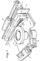
- Fig. 1 is a perspective view of a stamping apparatus in accordance with the invention, and
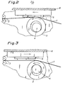
- Figs. 2 and 3 are lateral views of the apparatus, illustrating the latter in two different operational positions.
- A strip blank 1 which is to be stamped along its length with thread-groove, sections and which in a subsequent operation is to be severed and shaped into a hose clamp strip, is continuously advanced by a pair of
rollers 2 past asupport roll 3. Thesupport roll 3 is mounted on an eccentric shaft 4 which is positioned in parallel with the plane of the strip and perpendicularly to the direction of advancement of the latter. - A
stamping tool 5 the stamping face of which is formed to give the desired thread profiles is positioned on the opposite side of the strip 1 and is attached to aslide member 6 which is mounted for displacement in a plane which is essentially parallel to the plane of advancement of the strip. A bracket 7 mounted on theslide member 6 supports the piston rod of a piston-and-cylinder unit 8 arranged to displace the slide member to and fro. A second piston-and-cylinder unit 9 is secured to the eccentric shaft 4 via a lever.10. When the shaft 4 is turned with the aid of thelever 10 and the piston-and-cylinder unit 9 thesupport roll 3 may be.displaced transversely relative to the direction of advancement of the strip 1 towards or away from thestamping tool 5 between two end positions. - In the inner end position of the tool illustrated in Fig. 2 the
support roll 3 presses the strip 1 hard against thestamp tool 5. At the same time theslide member 6 is displaced by the piston-and-cylinder unit 8 in synchrony with the advancement of the strip by the pair ofrollers 2, the stamping action being effected in the press nip between thesupport roll 3 and thestamping tool 5. - When one thread section has been stamped, which is sensed by means provided to sense the movements of the
slide member 6, by a time relay or by means arranged to sense the advancement of the strip, the second piston-and-cylinder unit 9 is activated, which by turning the shaft 4 in the opposite direction effects displacement of thesupport roll 3 away from thestamping tool 5. As a result the strip 1 is no longer pressed against the stamping tool and the tool is allowed to complete its movement forwards out of contact with the strip 1. The stamping tool is then brought back to its original position by the piston-and-cylinder unit 8 to effect another stamping operation. The strip 1 is advanced continuously at a constant rate and when one strip section having a length corresponding to the desired gap between two threaded sections has moved past by thesupport roll 3 the piston--and-cylinder unit 9 is again activated and serves to press the support roll against thestamping tool 5 to effect another stamping operation. - The length of the stamped sections and the length of the unstamped sections separating them are easily varied by controlling the operation of the piston-and--cylinder 9 in such a manner that the
support roll 3 when abutting against the stamping tool at one end position of the stamping tool provides the desired length of the stamped section whereas the desired interruption between the stamped sections is effected in the other end position. - Because the stamping operations are effected successively over a short section of the length of the strip 1 most of the flow of the material will take place in the lengthwise direction of the strip whereas the difference in width will be minimal.
- The invention is not limited to the embodiment described in the aforegoing but modifications thereof are possible within the scope of the appended claims. The means for advancement of the
stamping tool 5, for example, are not essential, it being possible to shape the tool as a round stamping cylinder mounted on a shaft which is driven in synchrony with the speed of advancement of the strip. Other means than piston-and-cylinder units may be used to effect the movements of theslide member 6 and to operate the shaft 4.
Claims (2)
Priority Applications (1)
| Application Number | Priority Date | Filing Date | Title |
|---|---|---|---|
| AT84850021T ATE24286T1 (en) | 1983-01-21 | 1984-01-19 | APPARATUS FOR PRODUCTION OF EMPRESSED SECTIONS ON A CONTINUOUSLY CONVEYED STRIP MATERIAL. |
Applications Claiming Priority (2)
| Application Number | Priority Date | Filing Date | Title |
|---|---|---|---|
| SE8300300A SE439261B (en) | 1983-01-21 | 1983-01-21 | DEVICE FOR PREGNANT SECTION OF A LONG-TERM SINGLE CONTINUOUS FORMAT |
| SE8300300 | 1983-01-21 |
Publications (3)
| Publication Number | Publication Date |
|---|---|
| EP0114799A2 true EP0114799A2 (en) | 1984-08-01 |
| EP0114799A3 EP0114799A3 (en) | 1984-11-07 |
| EP0114799B1 EP0114799B1 (en) | 1986-12-17 |
Family
ID=20349698
Family Applications (1)
| Application Number | Title | Priority Date | Filing Date |
|---|---|---|---|
| EP84850021A Expired EP0114799B1 (en) | 1983-01-21 | 1984-01-19 | Apparatus for producing stamped sections in continuously advanced strip blank |
Country Status (5)
| Country | Link |
|---|---|
| EP (1) | EP0114799B1 (en) |
| JP (1) | JPS59162024A (en) |
| AT (1) | ATE24286T1 (en) |
| DE (1) | DE3461689D1 (en) |
| SE (1) | SE439261B (en) |
Cited By (1)
| Publication number | Priority date | Publication date | Assignee | Title |
|---|---|---|---|---|
| FR2707535A1 (en) * | 1993-07-13 | 1995-01-20 | Villareale Pino | Method for producing an internal thread in or an external thread on a component obtained by rolling |
Family Cites Families (5)
| Publication number | Priority date | Publication date | Assignee | Title |
|---|---|---|---|---|
| DE176939C (en) * | 1905-02-14 | |||
| US2394534A (en) * | 1943-10-28 | 1946-02-12 | Guy O Conner | Forming machine and feeding device therefor |
| BE513793A (en) * | 1944-07-09 | |||
| AT185655B (en) * | 1953-03-26 | 1956-05-25 | Fritz Dipl Ing Grah | Device for the production of incisions, stampings or deep-drawn depressions in continuously linearly traversing strips or profiles, eg. B. for lightweight supports |
| DE2942708A1 (en) * | 1979-10-23 | 1981-04-30 | Erich Schlemper Gmbh & Co Kg, 5620 Velbert | Tightening clamp for hose-clip - has curved pressure pads to conform to curvature of hose |
-
1983
- 1983-01-21 SE SE8300300A patent/SE439261B/en not_active IP Right Cessation
-
1984
- 1984-01-19 EP EP84850021A patent/EP0114799B1/en not_active Expired
- 1984-01-19 DE DE8484850021T patent/DE3461689D1/en not_active Expired
- 1984-01-19 AT AT84850021T patent/ATE24286T1/en active
- 1984-01-20 JP JP59007431A patent/JPS59162024A/en active Pending
Cited By (1)
| Publication number | Priority date | Publication date | Assignee | Title |
|---|---|---|---|---|
| FR2707535A1 (en) * | 1993-07-13 | 1995-01-20 | Villareale Pino | Method for producing an internal thread in or an external thread on a component obtained by rolling |
Also Published As
| Publication number | Publication date |
|---|---|
| DE3461689D1 (en) | 1987-01-29 |
| SE439261B (en) | 1985-06-10 |
| JPS59162024A (en) | 1984-09-12 |
| SE8300300L (en) | 1984-07-22 |
| SE8300300D0 (en) | 1983-01-21 |
| EP0114799B1 (en) | 1986-12-17 |
| EP0114799A3 (en) | 1984-11-07 |
| ATE24286T1 (en) | 1987-01-15 |
Similar Documents
| Publication | Publication Date | Title |
|---|---|---|
| KR880701984A (en) | Terminal strip crimp | |
| US3076368A (en) | Micro-adjustable strip stock feeder | |
| US4328729A (en) | Plane die-cutting machine | |
| GB1480164A (en) | Process and press for the cross-section of a slab | |
| US3792602A (en) | Apparatus for forming plates of irregular shape in cross-section | |
| US1925034A (en) | Prick punching machine | |
| EP0114799A2 (en) | Apparatus for producing stamped sections in continuously advanced strip blank | |
| RU2213638C2 (en) | Method for profiling strip of thin metallic sheet | |
| US3067999A (en) | Feed roll mounting and lifting device | |
| US2444706A (en) | Slide fastener machine | |
| JPS59104228A (en) | Strip feeder | |
| US5147080A (en) | Staple forming and stapling machine | |
| US3128028A (en) | Wire feeding device | |
| EP0366108B1 (en) | Device for the stepwise feeding of a strip | |
| SU596332A1 (en) | Web-making plant | |
| US3907188A (en) | Intermittent strip roll feed | |
| US4925081A (en) | Strip material feed guide | |
| US4149438A (en) | Press cutting apparatus | |
| US5025650A (en) | Apparatus for forming plates of irregular cross-sectional shape | |
| US2707995A (en) | Apparatus for making fine mesh expanded material | |
| SU1094652A1 (en) | Progressive die for strip and band material | |
| CN112692202A (en) | Novel straight nail single nail making machine | |
| US2050010A (en) | Machine for making and driving corrugated fasteners | |
| US3444768A (en) | Strip stock feed mechanism | |
| US2748402A (en) | Rivet blank holder transversely movable between header and ejector stations |
Legal Events
| Date | Code | Title | Description |
|---|---|---|---|
| PUAI | Public reference made under article 153(3) epc to a published international application that has entered the european phase |
Free format text: ORIGINAL CODE: 0009012 |
|
| AK | Designated contracting states |
Designated state(s): AT BE CH DE FR GB IT LI LU NL SE |
|
| PUAL | Search report despatched |
Free format text: ORIGINAL CODE: 0009013 |
|
| AK | Designated contracting states |
Designated state(s): AT BE CH DE FR GB IT LI LU NL SE |
|
| 17P | Request for examination filed |
Effective date: 19841219 |
|
| GRAA | (expected) grant |
Free format text: ORIGINAL CODE: 0009210 |
|
| AK | Designated contracting states |
Kind code of ref document: B1 Designated state(s): AT BE CH DE FR GB IT LI LU NL SE |
|
| PG25 | Lapsed in a contracting state [announced via postgrant information from national office to epo] |
Ref country code: NL Effective date: 19861217 Ref country code: LI Effective date: 19861217 Ref country code: IT Free format text: LAPSE BECAUSE OF FAILURE TO SUBMIT A TRANSLATION OF THE DESCRIPTION OR TO PAY THE FEE WITHIN THE PRESCRIBED TIME-LIMIT;WARNING: LAPSES OF ITALIAN PATENTS WITH EFFECTIVE DATE BEFORE 2007 MAY HAVE OCCURRED AT ANY TIME BEFORE 2007. THE CORRECT EFFECTIVE DATE MAY BE DIFFERENT FROM THE ONE RECORDED. Effective date: 19861217 Ref country code: CH Effective date: 19861217 Ref country code: BE Effective date: 19861217 Ref country code: AT Effective date: 19861217 |
|
| REF | Corresponds to: |
Ref document number: 24286 Country of ref document: AT Date of ref document: 19870115 Kind code of ref document: T |
|
| PG25 | Lapsed in a contracting state [announced via postgrant information from national office to epo] |
Ref country code: SE Effective date: 19861231 |
|
| REF | Corresponds to: |
Ref document number: 3461689 Country of ref document: DE Date of ref document: 19870129 |
|
| PG25 | Lapsed in a contracting state [announced via postgrant information from national office to epo] |
Ref country code: LU Free format text: LAPSE BECAUSE OF NON-PAYMENT OF DUE FEES Effective date: 19870131 |
|
| REG | Reference to a national code |
Ref country code: CH Ref legal event code: PL |
|
| ET | Fr: translation filed | ||
| NLV1 | Nl: lapsed or annulled due to failure to fulfill the requirements of art. 29p and 29m of the patents act | ||
| PLBE | No opposition filed within time limit |
Free format text: ORIGINAL CODE: 0009261 |
|
| STAA | Information on the status of an ep patent application or granted ep patent |
Free format text: STATUS: NO OPPOSITION FILED WITHIN TIME LIMIT |
|
| 26N | No opposition filed | ||
| REG | Reference to a national code |
Ref country code: FR Ref legal event code: TP |
|
| GBPC | Gb: european patent ceased through non-payment of renewal fee | ||
| PG25 | Lapsed in a contracting state [announced via postgrant information from national office to epo] |
Ref country code: GB Free format text: LAPSE BECAUSE OF NON-PAYMENT OF DUE FEES Effective date: 19881122 |
|
| PGFP | Annual fee paid to national office [announced via postgrant information from national office to epo] |
Ref country code: FR Payment date: 19890125 Year of fee payment: 6 |
|
| PGFP | Annual fee paid to national office [announced via postgrant information from national office to epo] |
Ref country code: DE Payment date: 19890216 Year of fee payment: 6 |
|
| PG25 | Lapsed in a contracting state [announced via postgrant information from national office to epo] |
Ref country code: FR Effective date: 19900928 |
|
| PG25 | Lapsed in a contracting state [announced via postgrant information from national office to epo] |
Ref country code: DE Effective date: 19901002 |
|
| REG | Reference to a national code |
Ref country code: FR Ref legal event code: ST |