EP0114800A2 - Eolienne à axe horizontal et nombre de pales réduit - Google Patents
Eolienne à axe horizontal et nombre de pales réduit Download PDFInfo
- Publication number
- EP0114800A2 EP0114800A2 EP84850022A EP84850022A EP0114800A2 EP 0114800 A2 EP0114800 A2 EP 0114800A2 EP 84850022 A EP84850022 A EP 84850022A EP 84850022 A EP84850022 A EP 84850022A EP 0114800 A2 EP0114800 A2 EP 0114800A2
- Authority
- EP
- European Patent Office
- Prior art keywords
- shaft
- clutch
- blades
- wind turbine
- bearing
- Prior art date
- Legal status (The legal status is an assumption and is not a legal conclusion. Google has not performed a legal analysis and makes no representation as to the accuracy of the status listed.)
- Ceased
Links
Images

Classifications
-
- F—MECHANICAL ENGINEERING; LIGHTING; HEATING; WEAPONS; BLASTING
- F03—MACHINES OR ENGINES FOR LIQUIDS; WIND, SPRING, OR WEIGHT MOTORS; PRODUCING MECHANICAL POWER OR A REACTIVE PROPULSIVE THRUST, NOT OTHERWISE PROVIDED FOR
- F03D—WIND MOTORS
- F03D7/00—Controlling wind motors
- F03D7/02—Controlling wind motors the wind motors having rotation axis substantially parallel to the air flow entering the rotor
- F03D7/022—Adjusting aerodynamic properties of the blades
- F03D7/0224—Adjusting blade pitch
-
- F—MECHANICAL ENGINEERING; LIGHTING; HEATING; WEAPONS; BLASTING
- F05—INDEXING SCHEMES RELATING TO ENGINES OR PUMPS IN VARIOUS SUBCLASSES OF CLASSES F01-F04
- F05B—INDEXING SCHEME RELATING TO WIND, SPRING, WEIGHT, INERTIA OR LIKE MOTORS, TO MACHINES OR ENGINES FOR LIQUIDS COVERED BY SUBCLASSES F03B, F03D AND F03G
- F05B2260/00—Function
- F05B2260/70—Adjusting of angle of incidence or attack of rotating blades
- F05B2260/74—Adjusting of angle of incidence or attack of rotating blades by turning around an axis perpendicular the rotor centre line
-
- F—MECHANICAL ENGINEERING; LIGHTING; HEATING; WEAPONS; BLASTING
- F05—INDEXING SCHEMES RELATING TO ENGINES OR PUMPS IN VARIOUS SUBCLASSES OF CLASSES F01-F04
- F05B—INDEXING SCHEME RELATING TO WIND, SPRING, WEIGHT, INERTIA OR LIKE MOTORS, TO MACHINES OR ENGINES FOR LIQUIDS COVERED BY SUBCLASSES F03B, F03D AND F03G
- F05B2260/00—Function
- F05B2260/70—Adjusting of angle of incidence or attack of rotating blades
- F05B2260/79—Bearing, support or actuation arrangements therefor
-
- Y—GENERAL TAGGING OF NEW TECHNOLOGICAL DEVELOPMENTS; GENERAL TAGGING OF CROSS-SECTIONAL TECHNOLOGIES SPANNING OVER SEVERAL SECTIONS OF THE IPC; TECHNICAL SUBJECTS COVERED BY FORMER USPC CROSS-REFERENCE ART COLLECTIONS [XRACs] AND DIGESTS
- Y02—TECHNOLOGIES OR APPLICATIONS FOR MITIGATION OR ADAPTATION AGAINST CLIMATE CHANGE
- Y02E—REDUCTION OF GREENHOUSE GAS [GHG] EMISSIONS, RELATED TO ENERGY GENERATION, TRANSMISSION OR DISTRIBUTION
- Y02E10/00—Energy generation through renewable energy sources
- Y02E10/70—Wind energy
- Y02E10/72—Wind turbines with rotation axis in wind direction
Definitions
- This invention relates to the type of wind turbines which rotates at high speed and has a horizontal shaft and few blades, and more particularly to an improved pitch regulation drive for such a turbine.
- wind power stations Because of the nature of wind power, which is characterized by varying wind speeds with relatively high amplitudes, wind power stations must be equipped with means for limiting variations in power and for limiting the force on the blades to moderate values.
- this limiting is provided by making the turbine blades such that they can twist about their longitudinal axes, so that the angle of twist, or pitch angle may be varied to suit variations in wind speed.
- pitch regulation is generally accomplished by an electronic-hydraulic system, where the required motive power is obtained from hydraulic cylinders placed in the rotating turbine hub.
- This location of the hydraulic cylinders creates severe technical problems allied to the fact that the whole of the hydraulic system, including cylinders, valves and accumulators, rotates with the turbine and must be connected to the stationary system via means permitting such rotation.
- One object here has been to have the motive power required for twisting the turbine blades provided by a power source having a more protected and accessible position inside the plant.
- a simple and reliable structure is also an object, since such plant is usually unmanned and remotely controlled.
- the wind turbine is provided with a device for turning or twisting the blades about their longitudinal axes, comprising a power source situated outside the turbine shaft and adapted to impart axial motion to an axially displaceable clutch mounted on the shaft, the clutch having two main parts in mutual coaction such that one part is rotationally stationary on the shaft, whereas the other part may rotate with the shaft. The part which rotates with the shaft is then coupled to the blades.
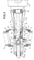
- Turbine shaft 1 is rotatably mounted on rolling bearings 2, 3 in a housing 4.
- the shaft 1 is at a diametrically enlarged portion la provided with a radial through- bore for a shaft 5, constituting the pivotal center for a hub 6.
- Turbine blades 9 and 10 are supported on the hub 6 through rolling bearings 7 and 8.
- the bearing housing 4 also carries a gearbox 11.
- the turbine shaft 1 constitutes the input shaft to gearbox 11, the output shaft thereof being connected to an electric generator (not illustrated).
- Hydraulic cylinders 13 are pivotably mounted at the housing 4 via pins 12 externally of bearings 3.
- the piston rods 14 of cylinders 13 are pivotably connected to a collar clutch, axially displaceably mounted on shaft 1 and comprising a first half 18 and a second half 16.
- the first half 18 of the clutch is mounted so as to rotate together with the shaft, but the second half 16 is non-rotatably guided upon the shaft.
- the two clutch halves 18 and 16, respectively, are interconnected by a roller bearing 17, holding the two parts together axially, but permitting relative rotation.
- the piston rods 14 of the hydraulic cylinders 13 pass through slots in the wall of the gearing housing, and are connected to the second clutch half 16 by gudgeons 15.
- a number of rods 19 are rigidly connected to the first clutch half.
- the diametrically enlarged portion la of the shaft 1 is journalled in the bearing 2, and is provided with bores 20, through which the rods 19 slidingly pass inside of bearing 2.
- a collar 21, axially displaceable on the shaft 1, is provided with bores of a diameter suited to, and in register with, the ends of rods 19.
- the ends of rods 19 have a reduced diameter and are threaded.
- Collar 21 is fitted over the ends of the rods, and is rigidly attached to them with the aid of nuts 25.
- Links 22 and 23 are pivotably attached to the collar 21, the other ends of the links being pivotably attached to the turbine blades 9 and 10, via a journalling pin 24, placed eccentrically in relation to the longitudinal axis of the respective blade.
- the invention is also applicable to turbine structures with so-called rigid hubs, or to turbines where each blade is attached to the hub in an articulated manner.
- the twisting movement of the blades is accomplished using hydraulic cylinders as a power source.
- the number of coacting cylinders may be one or more.
- other types of power sources such as pneumatic or electro-mechanical drives, e.g., an electric motor and rack and pinion drive, may be used.
Landscapes
- Engineering & Computer Science (AREA)
- Physics & Mathematics (AREA)
- Fluid Mechanics (AREA)
- Life Sciences & Earth Sciences (AREA)
- Sustainable Development (AREA)
- Sustainable Energy (AREA)
- Chemical & Material Sciences (AREA)
- Combustion & Propulsion (AREA)
- Mechanical Engineering (AREA)
- General Engineering & Computer Science (AREA)
- Wind Motors (AREA)
Applications Claiming Priority (2)
| Application Number | Priority Date | Filing Date | Title |
|---|---|---|---|
| US460025 | 1983-01-21 | ||
| US06/460,025 US4534705A (en) | 1983-01-21 | 1983-01-21 | Horizontal-shaft wind turbine with few blades |
Publications (2)
| Publication Number | Publication Date |
|---|---|
| EP0114800A2 true EP0114800A2 (fr) | 1984-08-01 |
| EP0114800A3 EP0114800A3 (fr) | 1984-08-29 |
Family
ID=23827119
Family Applications (1)
| Application Number | Title | Priority Date | Filing Date |
|---|---|---|---|
| EP84850022A Ceased EP0114800A3 (fr) | 1983-01-21 | 1984-01-20 | Eolienne à axe horizontal et nombre de pales réduit |
Country Status (4)
| Country | Link |
|---|---|
| US (1) | US4534705A (fr) |
| EP (1) | EP0114800A3 (fr) |
| DK (1) | DK26684A (fr) |
| ES (1) | ES529038A0 (fr) |
Cited By (2)
| Publication number | Priority date | Publication date | Assignee | Title |
|---|---|---|---|---|
| GB2209806A (en) * | 1987-08-28 | 1989-05-24 | Taylor Woodrow Const Ltd | Blade pitch change mechanism |
| FR2748296A1 (fr) * | 1996-05-06 | 1997-11-07 | Richer Bertrand Louis Isidore | Systeme de controle du calage des pales d'un aerogenerateur avec effet de reduction des charges dynamiques et extremes |
Families Citing this family (5)
| Publication number | Priority date | Publication date | Assignee | Title |
|---|---|---|---|---|
| CH666728A5 (de) * | 1985-01-18 | 1988-08-15 | Escher Wyss Gmbh | Rotor einer windkraftanlage. |
| US4718823A (en) * | 1987-02-24 | 1988-01-12 | United Technologies Corporation | Pitch changing mechanism for fan blades |
| US6514043B1 (en) | 1998-06-04 | 2003-02-04 | Forskningscenter Risø | Wind turbine hub |
| EP1126163A1 (fr) * | 2000-02-16 | 2001-08-22 | Turbowinds N.V./S.A. | Dispositif de réglage du pas de l'hélice pour turbine éolienne |
| JP5199607B2 (ja) * | 2007-05-25 | 2013-05-15 | 三菱重工業株式会社 | 風力発電装置のピッチ駆動装置および風力発電装置 |
Family Cites Families (21)
| Publication number | Priority date | Publication date | Assignee | Title |
|---|---|---|---|---|
| GB162999A (en) * | 1920-10-25 | 1921-05-12 | Andrew Fraser | Improvements in or relating to windmills |
| US1990814A (en) * | 1933-04-12 | 1935-02-12 | Castro Lizandro Fernandez | Variable pitch propeller |
| DE895129C (de) * | 1944-04-07 | 1953-10-29 | Ulrich Dr-Ing Huetter | Windkraftanlage zur Erzeugung von elektrischem Strom |
| FR1104473A (fr) * | 1954-05-10 | 1955-11-21 | Bretagne Atel Chantiers | Mécanisme de commande des pales d'une hélice à pales orientables portée par un arbre de couche entraîné par réducteur |
| US2832895A (en) * | 1956-01-31 | 1958-04-29 | Allgaier Werke Gmbh | Control apparatus for wind motors |
| US3056457A (en) * | 1961-03-03 | 1962-10-02 | Macfarland Robin Adair | Variable pitch propeller |
| FR1350013A (fr) * | 1962-12-08 | 1964-01-24 | Societe Anonyme, Etablissements Berry | Dispositif de commande de variation de pas en marche pour ventilateur |
| FR1402883A (fr) * | 1964-02-12 | 1965-06-18 | Nouveau type de moteur éolien | |
| GB1406834A (en) * | 1972-09-04 | 1975-09-17 | Stone Manganese Marine Ltd | Control valve actuating arrangements |
| DE2307656C3 (de) * | 1973-02-16 | 1979-01-04 | Motoren- Und Turbinen-Union Muenchen Gmbh, 8000 Muenchen | Vorrichtung zur Verstellung der Gebläselaufschaufeln eines Laufrades für Turbinenstrahltriebwerke |
| US3873236A (en) * | 1973-12-26 | 1975-03-25 | Gen Electric | Fan with variable pitch blades and translating bearing actuation system |
| FR2313576A1 (fr) * | 1975-06-06 | 1976-12-31 | Buys Victor | Machine eolienne a vitesse de rotation constante |
| DE2655026C2 (de) * | 1976-12-04 | 1979-01-18 | Ulrich Prof. Dr.-Ing. 7312 Kirchheim Huetter | Windenergiekonverter |
| US4084921A (en) * | 1977-04-05 | 1978-04-18 | Norz Gerald R | Windmill with cyclically feathering blades |
| DE2825061C2 (de) * | 1978-06-08 | 1981-09-24 | M.A.N. Maschinenfabrik Augsburg-Nürnberg AG, 8000 München | Windrad |
| US4362467A (en) * | 1979-02-08 | 1982-12-07 | Elliott Morris C | Variable pitch propeller device |
| AU5724480A (en) * | 1979-04-23 | 1980-10-30 | Maschinenfabrik Augsburg-Nurnberg Aktiengesellschaft | Wind motor vane pitch control |
| US4352634A (en) * | 1980-03-17 | 1982-10-05 | United Technologies Corporation | Wind turbine blade pitch control system |
| JPS56129799A (en) * | 1980-03-18 | 1981-10-12 | Ebara Corp | Variable pitch axial flow type blower |
| US4329117A (en) * | 1980-04-22 | 1982-05-11 | United Technologies Corporation | Wind turbine with drive train disturbance isolation |
| JPS57148073A (en) * | 1981-03-09 | 1982-09-13 | Tokyo Electric Power Co Inc:The | Variable pitch unit for blades |
-
1983
- 1983-01-21 US US06/460,025 patent/US4534705A/en not_active Expired - Fee Related
-
1984
- 1984-01-20 DK DK26684A patent/DK26684A/da not_active Application Discontinuation
- 1984-01-20 EP EP84850022A patent/EP0114800A3/fr not_active Ceased
- 1984-01-20 ES ES529038A patent/ES529038A0/es active Granted
Cited By (2)
| Publication number | Priority date | Publication date | Assignee | Title |
|---|---|---|---|---|
| GB2209806A (en) * | 1987-08-28 | 1989-05-24 | Taylor Woodrow Const Ltd | Blade pitch change mechanism |
| FR2748296A1 (fr) * | 1996-05-06 | 1997-11-07 | Richer Bertrand Louis Isidore | Systeme de controle du calage des pales d'un aerogenerateur avec effet de reduction des charges dynamiques et extremes |
Also Published As
| Publication number | Publication date |
|---|---|
| EP0114800A3 (fr) | 1984-08-29 |
| US4534705A (en) | 1985-08-13 |
| ES8501847A1 (es) | 1984-12-01 |
| ES529038A0 (es) | 1984-12-01 |
| DK26684D0 (da) | 1984-01-20 |
| DK26684A (da) | 1984-07-22 |
Similar Documents
| Publication | Publication Date | Title |
|---|---|---|
| KR850000935B1 (ko) | 풍동 터어빈 날개피치 조절 시스템 | |
| US4619585A (en) | Wind turbine apparatus | |
| US4366386A (en) | Magnus air turbine system | |
| RU2523515C2 (ru) | Устройство с подвижным силовым цилиндром для управления ориентацией лопатками вентилятора турбовинтового двигателя | |
| US4111601A (en) | Adjustable windmill | |
| AU2008320935B2 (en) | Blade pitch-angle control apparatus and wind turbine generator | |
| EP0266715A3 (fr) | Moyeu d'éolienne permettant le réglage de l'incidence des pales | |
| US4021142A (en) | Pitch-change apparatus for a ducted thrust fan | |
| CH709743A2 (de) | Vertikale Windkraftanlage sowie Verfahren zum Betrieb einer solchen Anlage. | |
| US5201239A (en) | Industrial robot with wrist actuator mechanism | |
| US20190024672A1 (en) | Fan module with variable-pitch blades for a turbine engine | |
| US4534705A (en) | Horizontal-shaft wind turbine with few blades | |
| GB2476326A (en) | Improvements relating to vertical axis turbines | |
| US20030015877A1 (en) | Wind power plant | |
| EP3269974A1 (fr) | Agencement de pas de pale de rotor | |
| CN103953504B (zh) | 电动直驱式风电变桨装置 | |
| US2501617A (en) | Variable pitch propeller operating mechanism for marine propulsion plants | |
| KR101294899B1 (ko) | 풍력 발전 장치의 피치 구동 장치 및 풍력 발전 장치 | |
| JP2691136B2 (ja) | 風車の可変ピッチ機構 | |
| FI91313B (fi) | Tuulivoimala ja menetelmä tuulivoimalan sähkögeneraattorin käytössä | |
| WO2009081438A3 (fr) | Dispositif de moteur hydraulique rotatif avec un axe vertical pour la production d'énergie | |
| CN112253381A (zh) | 一种叶片旋转机构 | |
| WO1995008708A1 (fr) | Dispositif permettant de convertir l'energie hydraulique ou eolienne | |
| US9790915B2 (en) | Turbine for a flow power plant | |
| EP0149467A1 (fr) | Moulin à vent comprenant un dispositif d'alignement automatique avec le vent |
Legal Events
| Date | Code | Title | Description |
|---|---|---|---|
| PUAI | Public reference made under article 153(3) epc to a published international application that has entered the european phase |
Free format text: ORIGINAL CODE: 0009012 |
|
| PUAL | Search report despatched |
Free format text: ORIGINAL CODE: 0009013 |
|
| AK | Designated contracting states |
Designated state(s): BE DE GB NL SE |
|
| AK | Designated contracting states |
Designated state(s): BE DE GB NL SE |
|
| 17P | Request for examination filed |
Effective date: 19841218 |
|
| STAA | Information on the status of an ep patent application or granted ep patent |
Free format text: STATUS: THE APPLICATION HAS BEEN REFUSED |
|
| 18R | Application refused |
Effective date: 19870402 |
|
| RIN1 | Information on inventor provided before grant (corrected) |
Inventor name: NYGREN, INGEMAR K. Inventor name: SELESTAM, RUNE K. |