EP0114890B1 - Procede et appareil de mesure de l'intensite d'un signal de haute frequence - Google Patents
Procede et appareil de mesure de l'intensite d'un signal de haute frequence Download PDFInfo
- Publication number
- EP0114890B1 EP0114890B1 EP83902772A EP83902772A EP0114890B1 EP 0114890 B1 EP0114890 B1 EP 0114890B1 EP 83902772 A EP83902772 A EP 83902772A EP 83902772 A EP83902772 A EP 83902772A EP 0114890 B1 EP0114890 B1 EP 0114890B1
- Authority
- EP
- European Patent Office
- Prior art keywords
- signal
- antenna
- antennas
- receiving means
- strength
- Prior art date
- Legal status (The legal status is an assumption and is not a legal conclusion. Google has not performed a legal analysis and makes no representation as to the accuracy of the status listed.)
- Expired
Links
- 238000000034 method Methods 0.000 title claims abstract description 21
- 238000005562 fading Methods 0.000 claims abstract description 16
- 238000004891 communication Methods 0.000 claims abstract description 10
- 238000005070 sampling Methods 0.000 claims description 10
- 230000008878 coupling Effects 0.000 claims description 3
- 238000010168 coupling process Methods 0.000 claims description 3
- 238000005859 coupling reaction Methods 0.000 claims description 3
- 230000001413 cellular effect Effects 0.000 abstract description 8
- 230000002093 peripheral effect Effects 0.000 abstract description 3
- 239000000523 sample Substances 0.000 description 8
- 238000006243 chemical reaction Methods 0.000 description 3
- 238000010586 diagram Methods 0.000 description 2
- 230000000694 effects Effects 0.000 description 2
- 230000001343 mnemonic effect Effects 0.000 description 2
- 239000004065 semiconductor Substances 0.000 description 2
- 230000011664 signaling Effects 0.000 description 2
- 238000012935 Averaging Methods 0.000 description 1
- 230000000977 initiatory effect Effects 0.000 description 1
- 238000005259 measurement Methods 0.000 description 1
- 238000012544 monitoring process Methods 0.000 description 1
- 238000012545 processing Methods 0.000 description 1
Images


Classifications
-
- H—ELECTRICITY
- H04—ELECTRIC COMMUNICATION TECHNIQUE
- H04B—TRANSMISSION
- H04B7/00—Radio transmission systems, i.e. using radiation field
- H04B7/24—Radio transmission systems, i.e. using radiation field for communication between two or more posts
- H04B7/26—Radio transmission systems, i.e. using radiation field for communication between two or more posts at least one of which is mobile
-
- H—ELECTRICITY
- H04—ELECTRIC COMMUNICATION TECHNIQUE
- H04B—TRANSMISSION
- H04B7/00—Radio transmission systems, i.e. using radiation field
- H04B7/02—Diversity systems; Multi-antenna system, i.e. transmission or reception using multiple antennas
- H04B7/04—Diversity systems; Multi-antenna system, i.e. transmission or reception using multiple antennas using two or more spaced independent antennas
- H04B7/08—Diversity systems; Multi-antenna system, i.e. transmission or reception using multiple antennas using two or more spaced independent antennas at the receiving station
- H04B7/0802—Diversity systems; Multi-antenna system, i.e. transmission or reception using multiple antennas using two or more spaced independent antennas at the receiving station using antenna selection
- H04B7/0805—Diversity systems; Multi-antenna system, i.e. transmission or reception using multiple antennas using two or more spaced independent antennas at the receiving station using antenna selection with single receiver and antenna switching
- H04B7/0808—Diversity systems; Multi-antenna system, i.e. transmission or reception using multiple antennas using two or more spaced independent antennas at the receiving station using antenna selection with single receiver and antenna switching comparing all antennas before reception
-
- H—ELECTRICITY
- H04—ELECTRIC COMMUNICATION TECHNIQUE
- H04B—TRANSMISSION
- H04B7/00—Radio transmission systems, i.e. using radiation field
- H04B7/02—Diversity systems; Multi-antenna system, i.e. transmission or reception using multiple antennas
- H04B7/04—Diversity systems; Multi-antenna system, i.e. transmission or reception using multiple antennas using two or more spaced independent antennas
- H04B7/08—Diversity systems; Multi-antenna system, i.e. transmission or reception using multiple antennas using two or more spaced independent antennas at the receiving station
- H04B7/0802—Diversity systems; Multi-antenna system, i.e. transmission or reception using multiple antennas using two or more spaced independent antennas at the receiving station using antenna selection
- H04B7/0805—Diversity systems; Multi-antenna system, i.e. transmission or reception using multiple antennas using two or more spaced independent antennas at the receiving station using antenna selection with single receiver and antenna switching
Definitions
- the present invention is related to co-pending European patent application No. 83902729.9, entitled “Scanning and Assigning Duplex Radio Channels to Mobile and Portable Radiotelephone in Cellular Radiotelephone Communications System", invented by Larry C. Puhl and Ronald J. Webb, and assigned to same assignee and filed the same date as the present invention.
- the present invention relates generally to radio frequency (RF) signal strength measuring apparatus, and more particularly to an improved method and apparatus for measuring the strength of an RF signal subject to rapid and deep fading, such as Rayleigh fading.
- RF radio frequency
- the strength of RF signals has been determined by averaging a number of samples taken either by an analog meter or an analog-to-digital converter.
- the resulting signal strength is reasonably accurate as long as the RF signal is not subject to rapid and deep fading.
- a signal strength sample taken during a deep fade will cause a large error in the computed average signal strength.
- the effects of a sample taken during a deep fade can be alleviated somewhat by taking a large number of samples over a relatively long time interval.
- the average of a small number of signal strength samples will not accurately reflect the true average signal strength due to the errors introduced by samples taken during deep fades.
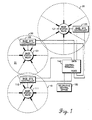
- FIG. 1 there is illustrated a cellular radiotelephone communications system of the type described in US patent numbers 3,663,762, 3,906,166; in an experimental cellular radio telephone system application filed under Docket No. 18262 with the Federal Communications Commission by Motorola and American Radio-Telephone Service, Inc. in February 1977; and more recently in a system description entitled "Motorola DYNATAC Cellular Radiotelephone Systems", published by Motorola Inc., Schaumburg, Illinois, in 1982.
- Such cellular systems can provide telephone coverage to both mobile and portable radiotelephones located throughout a large geographical area.
- Portable radiotelephones may be of the type described in US patent numbers 3,962,553 and 3,906,166; and mobile radiotelephones may be of the type described in Motorola instruction manual number 68P81039E25, published by Motorola Service Publications, Schaumburg, Illinois, 1979.
- the geographical area may be subdivided into cells 10,20 and 30, which each may include a base station radio 111, 121 and 131 and an associated base site controller 112, 122 and 132.
- Base site controllers 112, 122 and 132 are each coupled by data and voice links to a radio telephone control terminal 140, which may be similar to the terminals described in US patent number 3,663,762, 3,764,915, 3,819,872, 3,906,166 and 4,268,722.
- Control terminal 140 is in turn coupled to a conventional telephone central office 150 for completing telephone calls between mobile and portable radiotelephones and landline telephones.
- Each base station radio 111, 121 and 131 in Fig. 1 includes a plurality of transmitters and receivers for operating on at least one duplex signalling channel and a plurality of duplex voice channels.
- Base station 111, 121 and 131 may be of the type described in Motorola instruction manual number 68P81060E30, published by Motorola Service Publications, Motorola Inc., Schaumburg, Illinois, in 1982.
- Base station radios 111, 121 and 131 are located substantially at the center of each of the corresponding cells 10, 20 and 30.
- the base station transmitters may be combined onto one omni-directional antenna, while the base station receivers may be intercoupled to two or more directional or omni-directional sector antennas.
- the base station radios 111, 121 and 131 each include six 60° sector antennas.
- Each sector antenna primarily covers a portion of a cell, such as portion 21 of cell 20, and typically has a coverage area that overlaps the coverage area of adjacent sector antennas. Since the signalling channel requires an omni-directional receiving pattern, the signals received by the six sector antennas may be combined by a maximal ratio predetection diversity combiner, as illustrated and described in the present assignee's patent number US-A-4,369,520 issued 18 January 1983, entitled "Instantaneously Acquiring Sector Antenna System" and invented by Frank J. Cerny, Jr. and James J.
- the signal strength of the mobile or portable radiotelephone must be monitored by the base site controller 122.
- the mobile or portable radio telephone can be handed off to a base site controller 112 or 132 in another cell. Hand off involves transferring a particular mobile or portable radiotelephone from a duplex voice channel in one cell to a duplex voice channel in another cell.
- the strength of an RF signal can be quickly and accurately measured for each operating mobile and portable radiotelephone so that a particular mobile or portable radiotelephone can be reliably handed off before communications with it are degraded or interrupted due to weak signal conditions.
- the RF signal frequencies utilized in the cellular system in Fig. 1 are typically above 800 mHz, the RF signals are subject to random, deep and rapid fading, commonly referred to as Rayleigh fading.
- Rayleigh fading the problem of accurately determining the strength of RF signals from mobile and portable radiotelephones is complicated not only by the fact that there may be a large number of mobile and portable radiotelephones to monitor, but also by the fact that the RF signal from the mobile and portable radiotelephones is subject to Rayleigh fading.
- the base site controllers 112, 122 and 132 must be capable of rapidly and accurately measuring the signal strength from a large number of mobile and portable radiotelephones to prevent communications with them from being unacceptably degraded or interrupted.
- a reasonably accurate measure of the signal strength from operating mobile and portable radiotelephones can be obtained by sampling the strength of the RF signal from each mobile and portable radiotelephone at least two times during a predetermined time interval and selecting the sampled signal strength for each that has the largest magnitude.
- the peak signal strength for each mobile and portable radiotelephone is a reasonably accurate measure of the signal strength since the peak signal strength is relatively close to the true average signal strength.
- the peak signal strength is closer to the true average signal strength than an average of a number of signal strength samples that includes a sample taken in a null.
- a scanning receiver can be coupled to the sector antennas of each base station radio 111, 121 and 131 for periodically measuring the peak signal strength of each operating mobile and portable radiotelephone in each cell 10, 20 and 30.
- the scanning receiver may be part of base station radios 111, 121 and 131 in Figure 1.
- the scanning receiver in Figure 2 includes an antenna selector 102 that is coupled to each of six sector antennas of the base station radio.
- Binary input signals applied to antenna selector 102 by peripheral interface adapter (PIA) 108 cause antenna selector 102 to couple a selected one of the six sector antennas to receiver 104.
- the sector antennas and antenna selector 102 may be any conventional apparatus, such as that described in the aforementioned U.S. patent numbers 4,101,836 and 4,317,229.
- Receiver 104 may be a conventional synthesized receiver (such as the scanning receiver in the aforementioned Motorola instruction manual No. 68P81060E30), whose frequency of reception may be determined by an eleven-bit data signal applied to receiver 104 by PIA 108.
- the eleven-bit data signal is strobed into a register (not shown) of receiver 104 by a storage signal from PIA 108.
- An output from receiver 104 which is proportional to the instantaneous strength of the RF signal being received (e.g., such as the output of an envelope detector), is coupled to analog-to-digital converter (ADC) 106, which converts the magnitude of the receiver output to an eight-bit data signal.
- ADC analog-to-digital converter
- ADC 106 is controlled by PIA 110, which applies a start signal to ADC 106 for initiating the analog-to-digital conversion process.
- ADC 106 is also coupled to 600 kHz oscillator 112, and completes a conversion in approximately 120 microseconds. When the analog-to-digital conversion is complete, a complete signal is applied to PIA 110 by ADC 106.
- ADC 106 may be any suitable conventional analog-to-digital converter, such as, for example, an ADC0803 manufactured by National Semiconductor Corp.
- microprocessor 114 may be any suitable conventional microprocessor, such as, for example, a Motorola type MC6800 microprocessor. At predetermined time intervals, microprocessor 114 executes the flow chart in Figure 4 for measuring the signal strength of all active mobile and portable radiotelephones in its cell. Upon completion of the flowchart in Figure 4, microprocessor 114 has measured and stored the signal strength for each active mobile and portable radiotelephone and has determined which of the six sector antennas is receiving the strongest RF signal from each active mobile and portable radiotelephone.
- Microprocessor 114 is intercoupled to PIA's 108 and 110, read only memory (ROM) 116, random access memory (RAM) 118 and data interface 120 by way of data bus 124, address bus 126 and timing signals 128.
- ROM 116 stores a control program including subroutines for measuring the signal strength of active mobile and portable radiotelephones, such as the subroutine in the Appendix hereinbelow.
- RAM 118 is a scratch pad memory used during execution of the control program and subroutines.
- Data interface 120 provides a conventional data link between the scanning receiver in Figure 2 and other processing circuitry in the base site controllers 112, 122 and 132 in Figure 1.
- Microprocessor 114, PIA's 108 and 110, ROM 116, RAM 118, data interface 120 can each be provided by conventional integrated circuit devices, such as those described in the "Motorola Microprocessor Data Manual", published by the MOS Integrated Circuits Group of the Microprocessor Division of Motorola, Inc., Austin, Texas in 1981.
- microprocessor 114 may be a Motorola type MC6800 microprocessor, PIA's 108 and 110 a Motorola type MC6821 peripheral interface adapter, ROM 116 a Motorola type MCM68A316 2KX8 ROM, RAM 118 two Motorola type MCM2114 1 KX4 RAM's, and data interface 120, a Motorola type MC6850 or MC6852 data adapter.
- FIG. 4 a flow chart of the control program for microprocessor 114 in Figure 2 is illustrated.
- the flow chart may be executed periodically with all of the transmitting frequencies of active mobile and portable radiotelephones. Entering at START block 402, and proceeding to block 404, one of the active frequencies is loaded into receiver 104 in Figure 2.
- Block 406 the SCAN subroutine in the Appendix hereinbelow is executed.
- the SCAN subroutine samples each sector antenna a number of times determined by the variable COUNT and stores the largest sample for each sector antenna sequentially beginning at address IDAT. The scanning is repeated twenty-five times to provide some time diversity between signal strength measurements for each sector antenna.
- the sector antenna having the largest sample is identified by comparing the six samples stored at addresses IDAT, IDAT+1, IDAT+2, IDAT+3, IDAT+4 and IDAT+5.
- the selected sector antenna and its sampled signal strength may be stored in a location associated with the mobile or portable radiotelephone operating on the particular frequency.
- decision block 410 a check is made to see if all operating frequencies have been scanned. If all operating frequencies have been scanned, YES branch is taken to RETURN block 412. Otherwise, NO branch is taken to block 404 for scanning the next operating frequency.
- an improved method and apparatus for accurately measuring in a relatively short period of time the strength of an RF signal subject to Rayleigh fading has been described.
- the inventive method and apparatus is particularly well adapted for use in cellular radiotelephone systems, where it necessary to quickly and accurately measure the signal strength of mobile and portable radiotelephones so that communications with them can be maintained as they move from cell to cell.
- Table I hereinbelow illustrates a suitable program for the SCAN subroutine referred to in block 406 in the flow chart in Figure 4.
- the program is coded in mnemonic instructions for the Motorola type MC6800 microprocessor, which mnemonic instructions can be assembled into machine code instructions by a suitable assembler.
- the nmemonic instructions and operation of the Motorola type MC6800 microprocessor are described in further detail in a publication entitled, "Programming the 6800 Microprocessor", by R. W. Southern, published in 1977 and available from Motorola Semiconductor Products Inc., Literature Distribution Center, P.O. Box 20924, Phoenix, AZ 85036.
Landscapes
- Engineering & Computer Science (AREA)
- Computer Networks & Wireless Communication (AREA)
- Signal Processing (AREA)
- Mobile Radio Communication Systems (AREA)
- Testing Electric Properties And Detecting Electric Faults (AREA)
- Monitoring And Testing Of Transmission In General (AREA)
- Synchronisation In Digital Transmission Systems (AREA)
- Measurement Of Mechanical Vibrations Or Ultrasonic Waves (AREA)
- Investigating Strength Of Materials By Application Of Mechanical Stress (AREA)
- Input Circuits Of Receivers And Coupling Of Receivers And Audio Equipment (AREA)
- Channel Selection Circuits, Automatic Tuning Circuits (AREA)
- Circuits Of Receivers In General (AREA)
Claims (10)
Priority Applications (1)
| Application Number | Priority Date | Filing Date | Title |
|---|---|---|---|
| AT83902772T ATE26052T1 (de) | 1982-08-03 | 1983-08-02 | Verfahren und vorrichtung zum messen der intensitaet eines radiofrequenzsignals. |
Applications Claiming Priority (2)
| Application Number | Priority Date | Filing Date | Title |
|---|---|---|---|
| US40512382A | 1982-08-03 | 1982-08-03 | |
| US405123 | 1982-08-03 |
Publications (3)
| Publication Number | Publication Date |
|---|---|
| EP0114890A1 EP0114890A1 (fr) | 1984-08-08 |
| EP0114890A4 EP0114890A4 (fr) | 1984-10-11 |
| EP0114890B1 true EP0114890B1 (fr) | 1987-03-18 |
Family
ID=23602370
Family Applications (1)
| Application Number | Title | Priority Date | Filing Date |
|---|---|---|---|
| EP83902772A Expired EP0114890B1 (fr) | 1982-08-03 | 1983-08-02 | Procede et appareil de mesure de l'intensite d'un signal de haute frequence |
Country Status (15)
| Country | Link |
|---|---|
| EP (1) | EP0114890B1 (fr) |
| JP (1) | JPS59501530A (fr) |
| KR (1) | KR920001176B1 (fr) |
| AT (1) | ATE26052T1 (fr) |
| AU (1) | AU561186B2 (fr) |
| CA (1) | CA1209210A (fr) |
| DE (1) | DE3370422D1 (fr) |
| DK (1) | DK163700C (fr) |
| FI (1) | FI75958C (fr) |
| HK (1) | HK97489A (fr) |
| IL (1) | IL68987A (fr) |
| MX (1) | MX153718A (fr) |
| NO (1) | NO161890C (fr) |
| SG (1) | SG57689G (fr) |
| WO (1) | WO1984000653A1 (fr) |
Families Citing this family (7)
| Publication number | Priority date | Publication date | Assignee | Title |
|---|---|---|---|---|
| GB2253971B (en) * | 1984-10-30 | 1993-02-03 | Secr Defence | Improvements in or relating to ionospheric sounding |
| DE3508285C1 (de) * | 1985-03-08 | 1992-03-26 | Siemens Ag | Funkueberleitstelle fuer ein Mobilfunknetz |
| JPH0278331A (ja) * | 1988-09-14 | 1990-03-19 | Nec Corp | 移動通信用送受信装置 |
| CA2012120C (fr) * | 1989-03-15 | 1994-10-18 | Seiji Kondou | Detecteur de parasites pour systeme de communication mobile numerique |
| WO1992006566A1 (fr) * | 1990-10-01 | 1992-04-16 | Motorola, Inc. | Procede et appareil de transfert de donnees d'instructions individuelles |
| US5396224A (en) * | 1991-11-22 | 1995-03-07 | Hewlett-Packard Company | Telemetered patient location system and method |
| CN108964738B (zh) * | 2018-04-11 | 2021-09-28 | 莫志刚 | 一种用于轨道交通车地无线系统的车载天线系统 |
Family Cites Families (10)
| Publication number | Priority date | Publication date | Assignee | Title |
|---|---|---|---|---|
| FR1508349A (fr) * | 1966-11-24 | 1968-01-05 | Lannionaise D Electronique Soc | Dispositif automatique de commutation d'antenne |
| US3564287A (en) * | 1968-07-25 | 1971-02-16 | Us Navy | Maximum seeking zero order hold circuit |
| US3860872A (en) * | 1970-02-05 | 1975-01-14 | Pye Ltd | Multiple receiver selection system |
| US3896375A (en) * | 1974-02-06 | 1975-07-22 | United Kingdom Government | System for monitoring and indicating peak values of a time varying signal |
| US3973197A (en) * | 1974-07-22 | 1976-08-03 | Koehring Company | Peak detector |
| FR2319905A1 (fr) * | 1975-08-01 | 1977-02-25 | Thomson Csf | Dispositif de compression de bande et systeme radar comportant un tel dispositif |
| US4069455A (en) * | 1976-11-11 | 1978-01-17 | General Electric Company | Arrangement for maintaining reception of a radio receiver on the stronger of two signals |
| FR2379820A1 (fr) * | 1977-02-02 | 1978-09-01 | Cit Alcatel | Indicateur de puissance d'un signal |
| US4183087A (en) * | 1978-03-07 | 1980-01-08 | Hughes Aircraft Company | Peak deviation sampling |
| US4295099A (en) * | 1979-09-05 | 1981-10-13 | Honeywell Inc. | Peak detector |
-
1983
- 1983-06-14 IL IL68987A patent/IL68987A/xx not_active IP Right Cessation
- 1983-07-27 MX MX198179A patent/MX153718A/es unknown
- 1983-08-02 WO PCT/US1983/001180 patent/WO1984000653A1/fr not_active Ceased
- 1983-08-02 CA CA000433685A patent/CA1209210A/fr not_active Expired
- 1983-08-02 EP EP83902772A patent/EP0114890B1/fr not_active Expired
- 1983-08-02 DE DE8383902772T patent/DE3370422D1/de not_active Expired
- 1983-08-02 JP JP83502829A patent/JPS59501530A/ja active Pending
- 1983-08-02 AT AT83902772T patent/ATE26052T1/de not_active IP Right Cessation
- 1983-08-02 AU AU19424/83A patent/AU561186B2/en not_active Ceased
- 1983-08-03 KR KR1019830003634A patent/KR920001176B1/ko not_active Expired
-
1984
- 1984-03-30 FI FI841285A patent/FI75958C/fi not_active IP Right Cessation
- 1984-04-02 NO NO84841285A patent/NO161890C/no not_active IP Right Cessation
- 1984-04-03 DK DK176784A patent/DK163700C/da not_active IP Right Cessation
-
1989
- 1989-08-25 SG SG576/89A patent/SG57689G/en unknown
- 1989-12-07 HK HK974/89A patent/HK97489A/en not_active IP Right Cessation
Also Published As
| Publication number | Publication date |
|---|---|
| DK176784D0 (da) | 1984-04-03 |
| EP0114890A1 (fr) | 1984-08-08 |
| MX153718A (es) | 1986-12-22 |
| NO161890C (no) | 1989-10-04 |
| JPS59501530A (ja) | 1984-08-23 |
| SG57689G (en) | 1989-12-29 |
| FI75958B (fi) | 1988-04-29 |
| FI841285A7 (fi) | 1984-03-30 |
| EP0114890A4 (fr) | 1984-10-11 |
| DK176784A (da) | 1984-04-03 |
| FI75958C (fi) | 1988-08-08 |
| HK97489A (en) | 1989-12-15 |
| WO1984000653A1 (fr) | 1984-02-16 |
| IL68987A (en) | 1986-12-31 |
| FI841285A0 (fi) | 1984-03-30 |
| KR920001176B1 (ko) | 1992-02-06 |
| CA1209210A (fr) | 1986-08-05 |
| DE3370422D1 (en) | 1987-04-23 |
| AU1942483A (en) | 1984-02-23 |
| NO161890B (no) | 1989-06-26 |
| DK163700C (da) | 1992-08-10 |
| DK163700B (da) | 1992-03-23 |
| ATE26052T1 (de) | 1987-04-15 |
| KR840006078A (ko) | 1984-11-21 |
| NO841285L (no) | 1984-04-02 |
| IL68987A0 (en) | 1983-10-31 |
| AU561186B2 (en) | 1987-04-30 |
Similar Documents
| Publication | Publication Date | Title |
|---|---|---|
| US4549311A (en) | Method and apparatus for measuring the strength of a radio signal frequency | |
| US4485486A (en) | Method and apparatus for assigning duplex radio channels and scanning duplex radio channels assigned to mobile and portable radio telephones in a cellular radiotelephone communications system | |
| US4654879A (en) | Cellular mobile radio subscriber location detection | |
| US4608711A (en) | Cellular mobile radio hand-off utilizing voice channel | |
| US4751725A (en) | VOX remote unit control in a cellular system | |
| US6580910B1 (en) | Method and system for improving handoffs in cellular mobile radio systems | |
| EP0255628A2 (fr) | Circuit de transfert et méthode de réduction des interférences pour système radio | |
| EP0114890B1 (fr) | Procede et appareil de mesure de l'intensite d'un signal de haute frequence | |
| EP0115528B1 (fr) | Procede et appareil d'affectation de canaux radioelectriques duplex et d'exploration de canaux radioelectriques duplex affectes a des radiotelephones mobiles et portatifs dans un systeme de communication radiotelephonique cellulaire | |
| KR100467222B1 (ko) | 다중 주파수할당 기지국의 수신감도 측정방법 | |
| JP4024966B2 (ja) | アダプティブアレイ基地局 | |
| WO2000051364A2 (fr) | Procede d'acquisition de gain d'antenne dans un systeme cellulaire | |
| AU8981998A (en) | Measuring uplink interference in radio system, and base station | |
| EP0840532A2 (fr) | Méthode et appareil de sélection de sites de base dans un système de communication | |
| HK62190A (en) | Method and apparatus for assigning duplex radio channels and scanning duplex radio channels assigned to mobile and portable radiotelephones in a cellular radiotelephone communications system | |
| GB2369967A (en) | Received signal measurement using a diversity antenna | |
| HK1004592B (en) | Vox remote unit control in a cellular system |
Legal Events
| Date | Code | Title | Description |
|---|---|---|---|
| PUAI | Public reference made under article 153(3) epc to a published international application that has entered the european phase |
Free format text: ORIGINAL CODE: 0009012 |
|
| AK | Designated contracting states |
Designated state(s): AT CH DE FR GB LI NL SE |
|
| 17P | Request for examination filed |
Effective date: 19840324 |
|
| GRAA | (expected) grant |
Free format text: ORIGINAL CODE: 0009210 |
|
| AK | Designated contracting states |
Kind code of ref document: B1 Designated state(s): AT CH DE FR GB LI NL SE |
|
| REF | Corresponds to: |
Ref document number: 26052 Country of ref document: AT Date of ref document: 19870415 Kind code of ref document: T |
|
| REF | Corresponds to: |
Ref document number: 3370422 Country of ref document: DE Date of ref document: 19870423 |
|
| ET | Fr: translation filed | ||
| PLBE | No opposition filed within time limit |
Free format text: ORIGINAL CODE: 0009261 |
|
| STAA | Information on the status of an ep patent application or granted ep patent |
Free format text: STATUS: NO OPPOSITION FILED WITHIN TIME LIMIT |
|
| 26N | No opposition filed | ||
| PG25 | Lapsed in a contracting state [announced via postgrant information from national office to epo] |
Ref country code: AT Effective date: 19880802 |
|
| EAL | Se: european patent in force in sweden |
Ref document number: 83902772.9 |
|
| PGFP | Annual fee paid to national office [announced via postgrant information from national office to epo] |
Ref country code: CH Payment date: 19950725 Year of fee payment: 13 |
|
| PGFP | Annual fee paid to national office [announced via postgrant information from national office to epo] |
Ref country code: NL Payment date: 19950830 Year of fee payment: 13 |
|
| PG25 | Lapsed in a contracting state [announced via postgrant information from national office to epo] |
Ref country code: LI Effective date: 19960831 Ref country code: CH Effective date: 19960831 |
|
| PG25 | Lapsed in a contracting state [announced via postgrant information from national office to epo] |
Ref country code: NL Effective date: 19970301 |
|
| REG | Reference to a national code |
Ref country code: CH Ref legal event code: PL |
|
| NLV4 | Nl: lapsed or anulled due to non-payment of the annual fee |
Effective date: 19970301 |
|
| PGFP | Annual fee paid to national office [announced via postgrant information from national office to epo] |
Ref country code: GB Payment date: 20000703 Year of fee payment: 18 |
|
| PGFP | Annual fee paid to national office [announced via postgrant information from national office to epo] |
Ref country code: DE Payment date: 20000720 Year of fee payment: 18 |
|
| PGFP | Annual fee paid to national office [announced via postgrant information from national office to epo] |
Ref country code: SE Payment date: 20000802 Year of fee payment: 18 |
|
| PGFP | Annual fee paid to national office [announced via postgrant information from national office to epo] |
Ref country code: FR Payment date: 20000803 Year of fee payment: 18 |
|
| PG25 | Lapsed in a contracting state [announced via postgrant information from national office to epo] |
Ref country code: GB Free format text: LAPSE BECAUSE OF NON-PAYMENT OF DUE FEES Effective date: 20010802 |
|
| PG25 | Lapsed in a contracting state [announced via postgrant information from national office to epo] |
Ref country code: SE Free format text: LAPSE BECAUSE OF NON-PAYMENT OF DUE FEES Effective date: 20010803 |
|
| GBPC | Gb: european patent ceased through non-payment of renewal fee |
Effective date: 20010802 |
|
| EUG | Se: european patent has lapsed |
Ref document number: 83902772.9 |
|
| PG25 | Lapsed in a contracting state [announced via postgrant information from national office to epo] |
Ref country code: FR Free format text: LAPSE BECAUSE OF NON-PAYMENT OF DUE FEES Effective date: 20020430 |
|
| PG25 | Lapsed in a contracting state [announced via postgrant information from national office to epo] |
Ref country code: DE Free format text: LAPSE BECAUSE OF NON-PAYMENT OF DUE FEES Effective date: 20020501 |
|
| REG | Reference to a national code |
Ref country code: FR Ref legal event code: ST |
|
| P01 | Opt-out of the competence of the unified patent court (upc) registered |
Effective date: 20230520 |