EP0114913B1 - Soufflet d'intercommunication pour véhicules - Google Patents
Soufflet d'intercommunication pour véhicules Download PDFInfo
- Publication number
- EP0114913B1 EP0114913B1 EP19830100826 EP83100826A EP0114913B1 EP 0114913 B1 EP0114913 B1 EP 0114913B1 EP 19830100826 EP19830100826 EP 19830100826 EP 83100826 A EP83100826 A EP 83100826A EP 0114913 B1 EP0114913 B1 EP 0114913B1
- Authority
- EP
- European Patent Office
- Prior art keywords
- cable
- tensioning
- boot
- boot according
- toggle
- Prior art date
- Legal status (The legal status is an assumption and is not a legal conclusion. Google has not performed a legal analysis and makes no representation as to the accuracy of the status listed.)
- Expired
Links
- 230000008878 coupling Effects 0.000 claims description 12
- 238000010168 coupling process Methods 0.000 claims description 12
- 238000005859 coupling reaction Methods 0.000 claims description 12
- 230000000717 retained effect Effects 0.000 claims 2
- 241000237519 Bivalvia Species 0.000 claims 1
- 235000020639 clam Nutrition 0.000 claims 1
- 238000010276 construction Methods 0.000 description 2
- 238000007789 sealing Methods 0.000 description 2
- 230000007704 transition Effects 0.000 description 2
- 230000006835 compression Effects 0.000 description 1
- 238000007906 compression Methods 0.000 description 1
- 239000000428 dust Substances 0.000 description 1
- 239000004744 fabric Substances 0.000 description 1
- 230000002093 peripheral effect Effects 0.000 description 1
Images


Classifications
-
- B—PERFORMING OPERATIONS; TRANSPORTING
- B60—VEHICLES IN GENERAL
- B60D—VEHICLE CONNECTIONS
- B60D5/00—Gangways for coupled vehicles, e.g. of concertina type
- B60D5/003—Bellows for interconnecting vehicle parts
-
- B—PERFORMING OPERATIONS; TRANSPORTING
- B61—RAILWAYS
- B61D—BODY DETAILS OR KINDS OF RAILWAY VEHICLES
- B61D17/00—Construction details of vehicle bodies
- B61D17/04—Construction details of vehicle bodies with bodies of metal; with composite, e.g. metal and wood body structures
- B61D17/20—Communication passages between coaches; Adaptation of coach ends therefor
- B61D17/22—Communication passages between coaches; Adaptation of coach ends therefor flexible, e.g. bellows
-
- B—PERFORMING OPERATIONS; TRANSPORTING
- B62—LAND VEHICLES FOR TRAVELLING OTHERWISE THAN ON RAILS
- B62D—MOTOR VEHICLES; TRAILERS
- B62D47/00—Motor vehicles or trailers predominantly for carrying passengers
- B62D47/02—Motor vehicles or trailers predominantly for carrying passengers for large numbers of passengers, e.g. omnibus
- B62D47/025—Motor vehicles or trailers predominantly for carrying passengers for large numbers of passengers, e.g. omnibus articulated buses with interconnecting passageway, e.g. bellows
-
- F—MECHANICAL ENGINEERING; LIGHTING; HEATING; WEAPONS; BLASTING
- F16—ENGINEERING ELEMENTS AND UNITS; GENERAL MEASURES FOR PRODUCING AND MAINTAINING EFFECTIVE FUNCTIONING OF MACHINES OR INSTALLATIONS; THERMAL INSULATION IN GENERAL
- F16G—BELTS, CABLES, OR ROPES, PREDOMINANTLY USED FOR DRIVING PURPOSES; CHAINS; FITTINGS PREDOMINANTLY USED THEREFOR
- F16G11/00—Means for fastening cables or ropes to one another or to other objects; Caps or sleeves for fixing on cables or ropes
- F16G11/12—Connections or attachments, e.g. turnbuckles, adapted for straining of cables, ropes, or wire
Definitions
- the invention relates to a bellows according to the preamble of claim 1.
- Such bellows are used between the mutually facing ends of two articulated vehicle members to enclose a 'transition gate between these two vehicle members in a tunnel shape, so that people are protected from the wind, bad weather and dust can switch from one to the other vehicle link via the "transition bridge".
- the invention is concerned with the attachment of such a bellows on the two facing end faces of the two vehicle members.
- the vehicle wall is channel-shaped and a sealing profile is inserted into this channel running in the circumferential direction of the bellows.
- a tensioning cable is sewn into the associated bellows.
- the tensioning cable lies in the gutter of the vehicle wall and holds the bellows against the vehicle wall.
- either the tensioning cable must be elastic in itself or the distance between the ends of the essentially inextensible tensioning cable must be changeable.
- a tension cable that is essentially inextensible, the two ends of which are connected to each other in the area of the lower, horizontal bellows wall by a turnbuckle. If the turnbuckle is closed, the bellows end is fixed in the gutter of the respective vehicle link. Is the turnbuckle opened, the bellows can be removed from the trough-shaped end of the vehicle wall, so that it is separated from the vehicle member.
- the turnbuckle consists of two threaded pins, the pin ends of which are turned towards one another and can be screwed into a coupling piece to different degrees and the other ends of which act as a holder for the respective tension cable ends are formed.
- the object of the invention is to design a bellows of the type mentioned at the outset in such a way that it is much easier to use without significant additional construction work compared to the known solutions and without impairing the functionality.
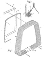
- a peripheral frame 2 is permanently assigned to the rear, open end of a front vehicle member 1, for example by being screwed onto the end face 3 of the vehicle member 1 (FIG. 1).
- the frame 2 is trough-shaped, i.e. it has the cross-section of a U with legs of different lengths (FIG. 2), the longer leg 4 being used to screw the frame onto the end face of the vehicle member.
- a tension cable 7 is sewn at its end, which lies in the channel-shaped bed of the frame 2.
- a rubber profile 6 is inserted into the frame bed and secured there, and the tensioning cable 7 is supported in the frame bed (with the bellows wall engaged) via this rubber profile.
- the tensioning cable 7 is tensioned in the end cloth of the bellows in order to prevent the bellows end from inadvertently reaching the shorter leg of the U of the frame 2.
- this voltage is generated or eliminated as follows. It is assumed that the bellows is configured identically at its two ends and is assigned to one end face of the two successive vehicle members with each of its ends.
- the two ends of the tensioning cable 7 are connected to one another in the region of the lower, horizontal bellows wall 5a with a toggle lever tensioner 8.
- the toggle lever clamp 8 is built on a base plate 9 which is held on two bearing blocks 10 (FIG. 3).
- Each bearing block 10 is provided with a bearing pin 12 pointing in the longitudinal direction of the vehicle, on which a lever 13 is pivotably mounted at one end.
- the other end of each lever 13 is designed as a manually operated handle 13a.
- a coupling rod 14 is articulated on a pin 15 of the lever 13, the longitudinal axis of which extends parallel to the longitudinal axis of the bearing pin 12.
- the coupling rod 14 has at its end facing away from the articulation a threaded section onto which two nuts 16, 17 are screwed at an axial distance. Between the two nuts 16, 17 there is a U-shaped coupling piece 18 with one leg, the nut 16 closer to the articulation of the coupling rod 14 on the lever 13 directly on the outside of the Leg of the coupling piece rests, while a spring element in the form of a plate spring 19 is located between the inside of this leg and the nut 17 lying further away from the articulation. On the other leg of the coupling piece, the tension cable 7 is attached at one end, for which purpose a clamping sleeve 20 is used.
- the ends of the tensioning cable are almost the smallest possible distance apart, so that the bellows is fixed relative to the end of the vehicle.
- the levers 13 are folded onto the base plate 9 with their handles 13a.
- the distance of the pin 15 from the base plate 9 is slightly less than the distance of the bearing pin 12.
- the levers 13 are pivoted about the bearing pin 12 in the direction of the arrows 21, the springs 19 being additionally tensioned until the pins 12, 15 and the spring 19 lie in a plane parallel to the base plate 9 in order to relax when the lever 13 is pivoted further, the distance between the ends of the tensioning cable 7 increasing and the bellows end being able to be lifted above the end frame.
- the device is thus easy to use, it is simple in construction and reliable.
- the operation is simple because only the levers 13 can be moved in one of two directions and a large change in the distance between the tension cable ends is possible by means of the two levers. Due to the possibility of changing the distance between the two tension cable ends, the bellows end can be reliably fixed in a relatively deep groove of the lead frame. Operational safety also benefits from the fact that when the lever is pivoted between its end positions, the point must be swiveled through in which the spring is maximally tensioned.
- the bias of the spring 19 can be changed, thereby changing the tension with which the respective tensioning cable is held in the groove of the bellows end.
- the effective basic length of the tensioning cable can be changed, it being advisable to make such changes to the two parts which are preferably to be provided. distribute the tensioning device evenly.
- the plane in which the tensioning levers 13 are to be pivoted in accordance with the arrows 21 is a plane parallel to the lower, horizontal bellows wall 5a, the tensioning levers 13 lying below the eyes 10, so that these are gripped by the bellows from one side and below them the tension levers are pivotable.
- a disk 3a is pivotally mounted about the longitudinal axis of the pin 2a by means of a vertical pin 2a.
- pins 4a and 5b two oppositely directed circular toggle levers 6a and 7a are articulated on the disk 3a.
- the toggle levers 6a, 7a are each articulated in a pin 100 or 200 to a clamping bolt 8a, 9a.
- the clamping bolts are adjustable in the direction of their longitudinal axes and for this purpose are each mounted in a bearing block 10a or 11a of the base plate 9.
- axially adjustable cable brackets 12c and 13c are mounted axially adjustable through longitudinal slots.
- the tensioning rope for tensioning and fixing the bellows at the vehicle end is fastened with its two ends, for which purpose these have saddle-shaped depressions in which the tensioning cable ends are suspended with lead-shaped receptacles.
- the articulation points 5b, 200 on the one hand and 4a, 100 on the other hand are on different sides of the pin 2a, the distance between the articulation points 100 and 200 and thus the ends of the rope is small, the rope is tensioned and pulls the end of it assigned bellows in a groove of the associated vehicle, on which the bellows is fixed in this way.
- the disk 3a is pivoted out of this operating position shown, so that the articulation points 4a, 100 on the one hand and 5b, 200 on the other hand are so laterally offset that the distance between the articulation points 100, 200 and thus the Rope ends is larger and the rope can be lifted out of the gutter of the vehicle and the bellows can be separated from the vehicle.
- the articulation points 100, 200 lie on a line which is axially aligned with the longitudinal axes of the clamping bolts 8a, 9a, while the articulation points 4a, 5b lie laterally from this line and when the disk is pivoted into the other position through this line be moved with which one .
- Ubertot Vietnamese Kunststoffhaloseun 9 for secure determination of the operating position shown given is.
- the pivotal movement of the disk 3a is a multi-surface pin 22 connected to it, on which a manually operated key can be attached.
- compression springs for example plate springs 12b, 13b, are inserted between each of the two cable brackets 12c, 13c and the lock nuts 12a, 13a associated therewith in order to be able to change the contact pressure of the tensioning cable to a limited extent in order to prevent the cable bracket from being inadvertently lifted off the lock nuts and in order to maintain a relative degree of freedom when tightening the lock nuts and in order to be able to compensate for different shrink widths of the vehicle, bellows and tensioning cable, especially at extreme temperatures.
Landscapes
- Engineering & Computer Science (AREA)
- Mechanical Engineering (AREA)
- General Engineering & Computer Science (AREA)
- Chemical & Material Sciences (AREA)
- Combustion & Propulsion (AREA)
- Transportation (AREA)
- Life Sciences & Earth Sciences (AREA)
- Wood Science & Technology (AREA)
- Flexible Shafts (AREA)
- Diaphragms And Bellows (AREA)
Claims (11)
Priority Applications (2)
| Application Number | Priority Date | Filing Date | Title |
|---|---|---|---|
| DE8383100826T DE3367352D1 (en) | 1983-01-28 | 1983-01-28 | Bellows connection for vehicle bodies |
| EP19830100826 EP0114913B1 (fr) | 1983-01-28 | 1983-01-28 | Soufflet d'intercommunication pour véhicules |
Applications Claiming Priority (1)
| Application Number | Priority Date | Filing Date | Title |
|---|---|---|---|
| EP19830100826 EP0114913B1 (fr) | 1983-01-28 | 1983-01-28 | Soufflet d'intercommunication pour véhicules |
Publications (2)
| Publication Number | Publication Date |
|---|---|
| EP0114913A1 EP0114913A1 (fr) | 1984-08-08 |
| EP0114913B1 true EP0114913B1 (fr) | 1986-11-05 |
Family
ID=8190270
Family Applications (1)
| Application Number | Title | Priority Date | Filing Date |
|---|---|---|---|
| EP19830100826 Expired EP0114913B1 (fr) | 1983-01-28 | 1983-01-28 | Soufflet d'intercommunication pour véhicules |
Country Status (2)
| Country | Link |
|---|---|
| EP (1) | EP0114913B1 (fr) |
| DE (1) | DE3367352D1 (fr) |
Families Citing this family (7)
| Publication number | Priority date | Publication date | Assignee | Title |
|---|---|---|---|---|
| DE8802944U1 (de) * | 1988-03-04 | 1988-08-04 | Hübner Gummi- und Kunststoff GmbH, 3500 Kassel | Spannvorrichtung |
| FR2629034B1 (fr) * | 1988-03-25 | 1990-04-20 | Caoutchouc Manuf Plastique | Membrane deformable pour tunnel d'intercirculation entre vehicules successifs ferroviaires ou routiers |
| FR2645097B1 (fr) * | 1989-03-28 | 1991-06-21 | Caoutchouc Manuf Plastique | Membrane deformable pour tunnel d'intercirculation entre vehicules successifs ferroviaires ou routiers a ondes de profondeur croissante |
| DE4105449A1 (de) * | 1991-02-21 | 1992-08-27 | Huebner Gummi & Kunststoff | Faltenbalg fuer uebergaenge von gelenkfahrzeugen, halteprofil fuer die befestigung eines solchen faltenbalgs an einem gelenkfahrzeug und bausatz aus einem solchen faltenbalg und einem solchen halteprofil sowie einbauverfahren |
| DE4330042A1 (de) * | 1993-09-06 | 1995-03-09 | Huebner Gummi & Kunststoff | Zwischen zwei gelenkig miteinander verbundenen Fahrzeuggliedern einsetzbarer Faltenbalg |
| AT8054U1 (de) | 2005-03-15 | 2006-01-15 | Ultimate Transp Equipment Gmbh | Faltenbalg - fahrzeuggliedbefestigung |
| CN110254455B (zh) * | 2019-07-02 | 2020-10-13 | 中车长春轨道客车股份有限公司 | 轨道车辆及其风挡吊挂装置 |
Family Cites Families (5)
| Publication number | Priority date | Publication date | Assignee | Title |
|---|---|---|---|---|
| BE421312A (fr) * | 1936-04-29 | |||
| FR1313154A (fr) * | 1961-11-08 | 1962-12-28 | Attache à tension et verrouillage rapide | |
| CH485535A (de) * | 1968-01-19 | 1970-02-15 | Huebner Kg Kurt | Faltenbalgverbindung an aus mehreren Abschnitten zusammengesetzten Fahrzeugen |
| GB1228200A (fr) * | 1968-11-14 | 1971-04-15 | ||
| DE2726724A1 (de) * | 1976-06-24 | 1978-01-05 | Max Frei | Drahtzaun-spanner |
-
1983
- 1983-01-28 EP EP19830100826 patent/EP0114913B1/fr not_active Expired
- 1983-01-28 DE DE8383100826T patent/DE3367352D1/de not_active Expired
Also Published As
| Publication number | Publication date |
|---|---|
| DE3367352D1 (en) | 1986-12-11 |
| EP0114913A1 (fr) | 1984-08-08 |
Similar Documents
| Publication | Publication Date | Title |
|---|---|---|
| EP0623490B1 (fr) | Porte-bagages pour véhicules à moteur avec rails de toit | |
| CH668232A5 (de) | Tragvorrichtung fuer eine last. | |
| DE69508847T2 (de) | Doppeltwirkende Klemme zum Ankuppeln eines Fahrzeuges an das Zugkabel | |
| DE29501244U1 (de) | Spannvorrichtung | |
| EP0114913B1 (fr) | Soufflet d'intercommunication pour véhicules | |
| DE69002308T2 (de) | Achshebevorrichtung fuer ein fahrzeug mit pneumatischem aufhaengesystem. | |
| DE3036580A1 (de) | Gelenkbeschlag fuer sitze mit verstellbarer rueckenlehne, insbesondere kraftfahrzeugsitze | |
| DE202012006839U1 (de) | Befestigungsklemme für Solarmodule | |
| DE3139697A1 (de) | Faltenbalg fuer fahrzeuge | |
| EP0396890A1 (fr) | Dispositif pour nettoyer des bandes de transport | |
| EP0776811A1 (fr) | Fixation d'un volant de direction | |
| DE20317350U1 (de) | Achsanhebevorrichtung für Nutzfahrzeuge | |
| DE3211940C2 (de) | Verstellhalterung für die Platte eines Zeichentisches | |
| EP2995502B1 (fr) | Agencement de galerie pour un véhicule automobile | |
| DE4112923A1 (de) | Klemmvorrichtung zum befestigen von glasplatten | |
| EP0644072B1 (fr) | Soufflet pour installation entre deux unités-véhicules accouplées par articulation | |
| DD202274A5 (de) | Schienenzange | |
| DE2126347C3 (de) | Vorrichtung zum Reinigen der Räder von Fahrzeugen | |
| CH641521A5 (en) | Setting-out device for windows or doors | |
| EP0596199A1 (fr) | Couvercle pour l'enceinte d'une centrifugeuse | |
| DE3605929C2 (fr) | ||
| EP0776020B1 (fr) | Dispositif d'interrupteur de sécurité | |
| AT394164B (de) | Lasttrageeinrichtung | |
| DE19959940B4 (de) | Lastträgerfuß | |
| EP0262094A1 (fr) | Trappe de déchargement pour matières en vrac fluides |
Legal Events
| Date | Code | Title | Description |
|---|---|---|---|
| PUAI | Public reference made under article 153(3) epc to a published international application that has entered the european phase |
Free format text: ORIGINAL CODE: 0009012 |
|
| AK | Designated contracting states |
Designated state(s): BE CH DE FR LI |
|
| 17P | Request for examination filed |
Effective date: 19850205 |
|
| GRAA | (expected) grant |
Free format text: ORIGINAL CODE: 0009210 |
|
| AK | Designated contracting states |
Kind code of ref document: B1 Designated state(s): BE CH DE FR LI |
|
| ET | Fr: translation filed | ||
| REF | Corresponds to: |
Ref document number: 3367352 Country of ref document: DE Date of ref document: 19861211 |
|
| PLBE | No opposition filed within time limit |
Free format text: ORIGINAL CODE: 0009261 |
|
| STAA | Information on the status of an ep patent application or granted ep patent |
Free format text: STATUS: NO OPPOSITION FILED WITHIN TIME LIMIT |
|
| 26N | No opposition filed | ||
| PGFP | Annual fee paid to national office [announced via postgrant information from national office to epo] |
Ref country code: CH Payment date: 19971209 Year of fee payment: 16 |
|
| PGFP | Annual fee paid to national office [announced via postgrant information from national office to epo] |
Ref country code: BE Payment date: 19971212 Year of fee payment: 16 |
|
| PGFP | Annual fee paid to national office [announced via postgrant information from national office to epo] |
Ref country code: FR Payment date: 19980128 Year of fee payment: 16 |
|
| PGFP | Annual fee paid to national office [announced via postgrant information from national office to epo] |
Ref country code: DE Payment date: 19980129 Year of fee payment: 16 |
|
| PG25 | Lapsed in a contracting state [announced via postgrant information from national office to epo] |
Ref country code: LI Free format text: LAPSE BECAUSE OF NON-PAYMENT OF DUE FEES Effective date: 19990131 Ref country code: CH Free format text: LAPSE BECAUSE OF NON-PAYMENT OF DUE FEES Effective date: 19990131 Ref country code: BE Free format text: LAPSE BECAUSE OF NON-PAYMENT OF DUE FEES Effective date: 19990131 |
|
| BERE | Be: lapsed |
Owner name: HUBNER GUMMI- UND KUNSTSTOFF G.M.B.H. Effective date: 19990131 |
|
| REG | Reference to a national code |
Ref country code: CH Ref legal event code: PL |
|
| PG25 | Lapsed in a contracting state [announced via postgrant information from national office to epo] |
Ref country code: FR Free format text: LAPSE BECAUSE OF NON-PAYMENT OF DUE FEES Effective date: 19990930 |
|
| PG25 | Lapsed in a contracting state [announced via postgrant information from national office to epo] |
Ref country code: DE Free format text: LAPSE BECAUSE OF NON-PAYMENT OF DUE FEES Effective date: 19991103 |
|
| REG | Reference to a national code |
Ref country code: FR Ref legal event code: ST |