EP0114915A2 - Werkzeugmaschine zum Bearbeiten der unteren Zylinder eines drehenden Videoaufnahmekopfes - Google Patents
Werkzeugmaschine zum Bearbeiten der unteren Zylinder eines drehenden Videoaufnahmekopfes Download PDFInfo
- Publication number
- EP0114915A2 EP0114915A2 EP83102900A EP83102900A EP0114915A2 EP 0114915 A2 EP0114915 A2 EP 0114915A2 EP 83102900 A EP83102900 A EP 83102900A EP 83102900 A EP83102900 A EP 83102900A EP 0114915 A2 EP0114915 A2 EP 0114915A2
- Authority
- EP
- European Patent Office
- Prior art keywords
- lead
- lower cylinder
- cutting
- cutting tool
- cam face
- Prior art date
- Legal status (The legal status is an assumption and is not a legal conclusion. Google has not performed a legal analysis and makes no representation as to the accuracy of the status listed.)
- Granted
Links
- 230000007547 defect Effects 0.000 description 3
- 230000000694 effects Effects 0.000 description 1
- 230000002452 interceptive effect Effects 0.000 description 1
- 230000002093 peripheral effect Effects 0.000 description 1
- 238000005096 rolling process Methods 0.000 description 1
Images


Classifications
-
- B—PERFORMING OPERATIONS; TRANSPORTING
- B23—MACHINE TOOLS; METAL-WORKING NOT OTHERWISE PROVIDED FOR
- B23Q—DETAILS, COMPONENTS, OR ACCESSORIES FOR MACHINE TOOLS, e.g. ARRANGEMENTS FOR COPYING OR CONTROLLING; MACHINE TOOLS IN GENERAL CHARACTERISED BY THE CONSTRUCTION OF PARTICULAR DETAILS OR COMPONENTS; COMBINATIONS OR ASSOCIATIONS OF METAL-WORKING MACHINES, NOT DIRECTED TO A PARTICULAR RESULT
- B23Q35/00—Control systems or devices for copying directly from a pattern or a master model; Devices for use in copying manually
- B23Q35/04—Control systems or devices for copying directly from a pattern or a master model; Devices for use in copying manually using a feeler or the like travelling along the outline of the pattern, model or drawing; Feelers, patterns, or models therefor
- B23Q35/42—Patterns; Masters models
- B23Q35/46—Supporting devices therefor
-
- B—PERFORMING OPERATIONS; TRANSPORTING
- B23—MACHINE TOOLS; METAL-WORKING NOT OTHERWISE PROVIDED FOR
- B23Q—DETAILS, COMPONENTS, OR ACCESSORIES FOR MACHINE TOOLS, e.g. ARRANGEMENTS FOR COPYING OR CONTROLLING; MACHINE TOOLS IN GENERAL CHARACTERISED BY THE CONSTRUCTION OF PARTICULAR DETAILS OR COMPONENTS; COMBINATIONS OR ASSOCIATIONS OF METAL-WORKING MACHINES, NOT DIRECTED TO A PARTICULAR RESULT
- B23Q35/00—Control systems or devices for copying directly from a pattern or a master model; Devices for use in copying manually
- B23Q35/04—Control systems or devices for copying directly from a pattern or a master model; Devices for use in copying manually using a feeler or the like travelling along the outline of the pattern, model or drawing; Feelers, patterns, or models therefor
- B23Q35/08—Means for transforming movement of the feeler or the like into feed movement of tool or work
- B23Q35/10—Means for transforming movement of the feeler or the like into feed movement of tool or work mechanically only
- B23Q35/101—Means for transforming movement of the feeler or the like into feed movement of tool or work mechanically only with a pattern composed of one or more lines used simultaneously for one tool
- B23Q35/102—Means for transforming movement of the feeler or the like into feed movement of tool or work mechanically only with a pattern composed of one or more lines used simultaneously for one tool of one line
- B23Q35/103—Means for transforming movement of the feeler or the like into feed movement of tool or work mechanically only with a pattern composed of one or more lines used simultaneously for one tool of one line which turns continuously
Definitions
- Fig. 1 is a schematic plan view, partly in section, of a main part of a conventional cutting machine
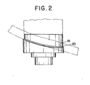
- Fig. 2 is a front view of a lower cylinder for rotary head video tape player
- Fig. 3 is a schematic plan view, partly in section, of a cutting machine given in one embodiment of this invention
- Fig. 4 is a flat pattern of a lead outer surface of the lower cylinder according to this invention.
- This invention relates to a cutting machine capable of cutting with precision a lead for helical scan of a lower cylinder for a rotary head video tape player.
- a lead of helical scan is the most important part to guide a magnetic tape for running, and cutting a helical curve of the lead with high precision may exert a big influence on a quality improvement of video tape playing.
- a lead cutting tool and a lead outer surface cutting tool are guided, hitherto, to reciprocate in a generating line direction of the lower cylinder by one cam face, as illustrated in Fig. 1.
- a chuck 4 for holding a lower cylinder 3 and a --shaped cam plate 5 are fixed concentrically on an end of a main spindle 2 supported on a headstock 1 on a lathe bed (not illustrated).
- a guide cam face 7 having a curved surface similar to a helical scan 6 formed on the outer surface of the lower cylinder is formed on the top of a peripheral raise of the cam plate 5.
- a cutting tool support 8 supported on a tool rest (not illustrated) installed on a carriage on the bed having a feed means orthogonal to a main spindle has a means (not illusteated) shakable in a generating line direction of the lower cylinder 3 held on the chuck 4 and also energized in the direction of being pressed onto the cam face 7. Therefore, a cam roller 9 borne on the cutting tool support 8 is pressed onto the cam face 7 at all times and has the cutting tool support 8 shake in reciprocation in the generating line direction of the lower cylinder 3 following the cam face.
- a means to feed a cutting tool mount 12 on which a lead cutting tool 10 and a lead outer surface cutting tool 11 are installed in the generating line direction of the held lower cylinder 3, i.e., the direction in which the cutting tool support 8 shakes in reciprocation is provided on the cutting tool support 8.
- a pressure oil chamber 13 is provided in the cutting tool support 8
- a hydraulic piston 14 is fitted in the chamber 13 to form a reciprocation guide face 16 for a rod 15 of the piston 14
- the cutting tool mount 12 is fixed on the rod 15
- a tool feeding pressure oil supply/ exhaust port 17 to actuate the piston 14 and a tool return pressure oil supply/exhaust port 18 are provided in the pressure oil chamber 13, and these supply/exhaust ports 17. and 18 are coupled to a hydraulic control unit (not illustrated) through a flexible tube.
- an interval between the lead cutting tool 10 and the lead outer surface cutting tool 11 in the generating line direction of the lower cylinder 3 is taken reasonably wide so as not to allow the tool 11 to interfere with the lower cylinder 3 at the time of lead cutting, and the tip of the lead cutting tool 10 is retreated from the outer surface on the lower cylinder 3 somewhat longer than the tip of the lead outer surface cutting tool 11 so as not to allow the lead cutting tool 10 to interfere with the outer surface of the lower cylinder 3 when an outer surface of the lower cylinder 3 is cut with the lead outer surface cutting tool 11.
- the lower cylinder 3 held on the chuck 4 rotates in accordance as the main spindle 2 is driven to rotate, and the cam plate 5 also rotates concurrently, therefore the cutting tool support 8 shakes in reciprocation following the guide cam face 7 in the generating line direction of the lower cylinder 3 through the roller 9 energized onto the guide cam face 7, gives a feed corresponding to a cutting allowance in the direction orthogonal to the main spindle to the tool.
- the lead outer surface is cut and so formed on the outer surface of the lower cylinder 3.
- the piston 14 is repushed by arranging the tool feeding pressure oil supply/exhaust port 17 to communicate with an oil tank and the tool return pressure oil supply/ exhaust port 18 with an oil pressure source, the lead outer surface cutting tool 11 thus comes off the outer surface of the lower cylinder 3, the lead cutting tool 10 is set then on a lead cutting position, a feed in the direction orthogonal to the main spindle 2 is given to the tool rest, and thus an undercut 19 of the lead and the lead 20 are finished, as illustrated in Fig. 2, with the lead cutting tool 10.
- a helical scan is cut and so formed on the lower cylinder for rotary head video tape player as described above; however, about 200 revolutions of the main spindle are necessary for completing a cutting of the lead outer surface, and also about 40 revolutions of the main spindle are necessary for completing a cut finish of the lead, which is generally well known. Namely,.
- the guide cam face 7 is subjected to a rolling press action 200 times or so repeatedly by the cam roller 9 before cutting of the lead outer surface is completed, a wear loss on the guide cam face 7 due to the cam roller 9 cannot be neglected, exerting an influence most severely on the performance of a video tape player; however, a finishing of the lead 20 which requires a superhigh precision has been carried out hitherto on the basis of the guide cam face 7 which has already been worn out through cutting of the lead outer surface, and thus an unavoidable defect was that a superhigh precision finishing could never be realized.
- a cam plate for cutting the lead is provided separately from that for cutting the lead outer surface thereby suppressing a wear on the lead cam face used at the time of lead cutting to secure a superhigh precision finishing of the lead; and the present invention comprises a chuck for holding a lower cylinder for a rotary head video tape player mounted on an end of a main spindle supported rotatably on a headstock on a bed, a lead cutting cam plate having a guide cam face for a lead of helical scan of the lower cylinder and at least one lead outer surface cutting cam plate having a lead outer surface guide cam face mounted concentrically on the main spindle, a cutting tool support guided selectively by each of the above cam faces to reciprocate in the direction of a generating line of the lower cylinder and also adjustable for moving radially of the lower cylinder installed on a tool rest on the bed, and a lead cutting tool .and a lead outer surface cutting tool both mounted-on the cutting tool support-hav
- Fig. 3 represents an arrangement in which a lead cutting cam plate and one lead outer surface cutting cam plate are mounted, like reference numerals denoting like members in 'Fig. 1; a numeral 21 denotes a lead outer surface cutting cam plate having a lead outer surface guide cam face 22 fixed concentrically on the main spindle 2 therewith, and a numeral 23 denotes a lead cutting cam plate having a lead guide cam face 24 fixed concentrically on the main spindle 2, both guide cam faces 22 and 24 forming a helical curve analogous to the helical scan 6.
- cam faces 22 and 24 of the lead cutting cam plate and the lead outer surface cutting cam plate are analogous each other and made to coincide in angled positions for use in the majority of cases; however, a cutting path of the lead outer surface and that of the lead due to a nonconformity of the centers between the lead cutting tool and the lead outer surface cutting tool can be made to coincide by adjusting a mutual angle phase of both the cam faces.
- each cam plate is mounted concentrically, which is convenient for replacement at the time of wear on the cam face or change and selection of the cam face shape; however, it goes without saying that a plurality of concentrical cam faces can be formed on one cam plate when each cam plate need not be replaced separately.
- the lead cutting guide cam face can be disposed either on the innermost side or on the outermost side by selecting a relative position for mounting both the tools.
- the lead cutting guide cam face for which the highest precision is required is used only at the time of lead cutting, the lead outer surface cutting guide cam face is formed separately from the lead cutting guide cam face,: therefore a cutting precision of the lead is remarkably improved by suppressing a wear on the lead cutting guide cam face, a precision of guiding the tape for running is also improved, and thus an excellent effect can be secured to improve a video tape playing function.
Landscapes
- Engineering & Computer Science (AREA)
- Automation & Control Theory (AREA)
- Mechanical Engineering (AREA)
- Turning (AREA)
- Machine Tool Copy Controls (AREA)
- Magnetic Heads (AREA)
Priority Applications (1)
| Application Number | Priority Date | Filing Date | Title |
|---|---|---|---|
| AT83102900T ATE28046T1 (de) | 1983-02-01 | 1983-03-23 | Werkzeugmaschine zum bearbeiten der unteren zylinder eines drehenden videoaufnahmekopfes. |
Applications Claiming Priority (2)
| Application Number | Priority Date | Filing Date | Title |
|---|---|---|---|
| JP13794/83 | 1983-02-01 | ||
| JP58013794A JPS59142003A (ja) | 1983-02-01 | 1983-02-01 | 回転ヘツド型磁気録画再生装置用下部シリンダのヘリカルスキヤン加工装置 |
Publications (3)
| Publication Number | Publication Date |
|---|---|
| EP0114915A2 true EP0114915A2 (de) | 1984-08-08 |
| EP0114915A3 EP0114915A3 (en) | 1984-09-05 |
| EP0114915B1 EP0114915B1 (de) | 1987-07-01 |
Family
ID=11843149
Family Applications (1)
| Application Number | Title | Priority Date | Filing Date |
|---|---|---|---|
| EP83102900A Expired EP0114915B1 (de) | 1983-02-01 | 1983-03-23 | Werkzeugmaschine zum Bearbeiten der unteren Zylinder eines drehenden Videoaufnahmekopfes |
Country Status (4)
| Country | Link |
|---|---|
| EP (1) | EP0114915B1 (de) |
| JP (1) | JPS59142003A (de) |
| AT (1) | ATE28046T1 (de) |
| DE (1) | DE3372266D1 (de) |
Cited By (1)
| Publication number | Priority date | Publication date | Assignee | Title |
|---|---|---|---|---|
| WO2015063750A1 (en) * | 2013-11-04 | 2015-05-07 | Bombardier Inc. | Guiding apparatus |
Families Citing this family (1)
| Publication number | Priority date | Publication date | Assignee | Title |
|---|---|---|---|---|
| US4831244A (en) * | 1987-10-01 | 1989-05-16 | Polaroid Corporation | Optical record cards |
Family Cites Families (6)
| Publication number | Priority date | Publication date | Assignee | Title |
|---|---|---|---|---|
| DE120541C (de) * | ||||
| DE1152871B (de) * | 1959-05-22 | 1963-08-14 | Schuette Fa Alfred H | Vorschubeinrichtung, insbesondere zum Gewindestrehlen |
| CH509132A (fr) * | 1969-06-20 | 1971-06-30 | Dubied & Cie Sa E | Dispositif palpeur pour le copiage sur machine-outil |
| JPS50145986A (de) * | 1974-05-15 | 1975-11-22 | ||
| WO1982002016A1 (fr) * | 1980-12-11 | 1982-06-24 | Ichiyanagi Takashi | Dispositif d'entrainement de came de copie pour machine outil |
| JPS584341A (ja) * | 1981-07-01 | 1983-01-11 | Hitachi Ltd | リ−ド加工機 |
-
1983
- 1983-02-01 JP JP58013794A patent/JPS59142003A/ja active Granted
- 1983-03-23 EP EP83102900A patent/EP0114915B1/de not_active Expired
- 1983-03-23 AT AT83102900T patent/ATE28046T1/de not_active IP Right Cessation
- 1983-03-23 DE DE8383102900T patent/DE3372266D1/de not_active Expired
Cited By (1)
| Publication number | Priority date | Publication date | Assignee | Title |
|---|---|---|---|---|
| WO2015063750A1 (en) * | 2013-11-04 | 2015-05-07 | Bombardier Inc. | Guiding apparatus |
Also Published As
| Publication number | Publication date |
|---|---|
| EP0114915A3 (en) | 1984-09-05 |
| JPS59142003A (ja) | 1984-08-15 |
| ATE28046T1 (de) | 1987-07-15 |
| JPS6222721B2 (de) | 1987-05-19 |
| DE3372266D1 (en) | 1987-08-06 |
| EP0114915B1 (de) | 1987-07-01 |
Similar Documents
| Publication | Publication Date | Title |
|---|---|---|
| GB2078574A (en) | Automatic drill point grinding machine | |
| JPH027762B2 (de) | ||
| US5529529A (en) | Cylinder liner microfinishing apparatus and method | |
| EP0114915A2 (de) | Werkzeugmaschine zum Bearbeiten der unteren Zylinder eines drehenden Videoaufnahmekopfes | |
| EP0111936B1 (de) | Feinschleifmaschine für ringförmige Werkstücke | |
| JP5287217B2 (ja) | 超仕上げ装置 | |
| US5088358A (en) | Automatic dual-side saw blade grinder having common blade advancement and clamp actuator and method of using same | |
| GB2080161A (en) | Machine tool index table drive apparatus | |
| US2350229A (en) | Surface grinder and automatic control means therefor | |
| EP0493389B1 (de) | Maschine zum schärfen von messern | |
| US4165661A (en) | Machine tool construction | |
| EP0970924A2 (de) | Vorrichtung zum Schneiden von Glasscheiben | |
| EP0575296B1 (de) | Schleifmaschine mit Schleifscheiben in veränderbarem Zustand | |
| EP0665077B1 (de) | Zahnradnachbearbeitungsmaschine | |
| US3533191A (en) | Profile grinding machines | |
| US3513596A (en) | Grinding machines with grinding-wheel wear compensating device | |
| GB2129725A (en) | Equipment for stamping or embossing a metallic workpiece | |
| US2076773A (en) | Machine for working printing machine cylinders, particularly copper cylinders in copperplate printing machines | |
| US20060096435A1 (en) | Apparatus to simultaneously cut apertures and perimeter contours in a sheet-type work material | |
| JP4090748B2 (ja) | ワーク加工装置 | |
| US3212371A (en) | Cam-operated turning, boring and facing attachment for lathes | |
| RU1797560C (ru) | Станок дл заточки сверл | |
| US4058933A (en) | Internal grinder | |
| SU814672A1 (ru) | Механизм подачи станка дл обра-бОТКи ОпТичЕСКиХ дЕТАлЕй | |
| US20070066182A1 (en) | Machine for grinding internal diameter and end surface of workpiece |
Legal Events
| Date | Code | Title | Description |
|---|---|---|---|
| PUAI | Public reference made under article 153(3) epc to a published international application that has entered the european phase |
Free format text: ORIGINAL CODE: 0009012 |
|
| PUAL | Search report despatched |
Free format text: ORIGINAL CODE: 0009013 |
|
| 17P | Request for examination filed |
Effective date: 19830323 |
|
| AK | Designated contracting states |
Designated state(s): AT CH DE FR GB IT LI NL |
|
| AK | Designated contracting states |
Designated state(s): AT CH DE FR GB IT LI NL |
|
| ITF | It: translation for a ep patent filed | ||
| GRAA | (expected) grant |
Free format text: ORIGINAL CODE: 0009210 |
|
| AK | Designated contracting states |
Kind code of ref document: B1 Designated state(s): AT CH DE FR GB IT LI NL |
|
| REF | Corresponds to: |
Ref document number: 28046 Country of ref document: AT Date of ref document: 19870715 Kind code of ref document: T |
|
| REF | Corresponds to: |
Ref document number: 3372266 Country of ref document: DE Date of ref document: 19870806 |
|
| ET | Fr: translation filed | ||
| PLBE | No opposition filed within time limit |
Free format text: ORIGINAL CODE: 0009261 |
|
| STAA | Information on the status of an ep patent application or granted ep patent |
Free format text: STATUS: NO OPPOSITION FILED WITHIN TIME LIMIT |
|
| 26N | No opposition filed | ||
| PGFP | Annual fee paid to national office [announced via postgrant information from national office to epo] |
Ref country code: AT Payment date: 19910228 Year of fee payment: 9 |
|
| ITTA | It: last paid annual fee | ||
| PGFP | Annual fee paid to national office [announced via postgrant information from national office to epo] |
Ref country code: CH Payment date: 19910415 Year of fee payment: 9 |
|
| PGFP | Annual fee paid to national office [announced via postgrant information from national office to epo] |
Ref country code: DE Payment date: 19910430 Year of fee payment: 9 |
|
| PGFP | Annual fee paid to national office [announced via postgrant information from national office to epo] |
Ref country code: GB Payment date: 19920224 Year of fee payment: 10 |
|
| PGFP | Annual fee paid to national office [announced via postgrant information from national office to epo] |
Ref country code: FR Payment date: 19920306 Year of fee payment: 10 |
|
| PG25 | Lapsed in a contracting state [announced via postgrant information from national office to epo] |
Ref country code: AT Effective date: 19920323 |
|
| PG25 | Lapsed in a contracting state [announced via postgrant information from national office to epo] |
Ref country code: LI Effective date: 19920331 Ref country code: CH Effective date: 19920331 |
|
| PGFP | Annual fee paid to national office [announced via postgrant information from national office to epo] |
Ref country code: NL Payment date: 19920331 Year of fee payment: 10 |
|
| REG | Reference to a national code |
Ref country code: CH Ref legal event code: PL |
|
| PG25 | Lapsed in a contracting state [announced via postgrant information from national office to epo] |
Ref country code: DE Effective date: 19921201 |
|
| PG25 | Lapsed in a contracting state [announced via postgrant information from national office to epo] |
Ref country code: GB Effective date: 19930323 |
|
| PG25 | Lapsed in a contracting state [announced via postgrant information from national office to epo] |
Ref country code: NL Effective date: 19931001 |
|
| NLV4 | Nl: lapsed or anulled due to non-payment of the annual fee | ||
| GBPC | Gb: european patent ceased through non-payment of renewal fee |
Effective date: 19930323 |
|
| PG25 | Lapsed in a contracting state [announced via postgrant information from national office to epo] |
Ref country code: FR Effective date: 19931130 |
|
| REG | Reference to a national code |
Ref country code: FR Ref legal event code: ST |