EP0114935A2 - Dispositif de découpe avec un dispositif de transport et d'inspection - Google Patents
Dispositif de découpe avec un dispositif de transport et d'inspection Download PDFInfo
- Publication number
- EP0114935A2 EP0114935A2 EP83109988A EP83109988A EP0114935A2 EP 0114935 A2 EP0114935 A2 EP 0114935A2 EP 83109988 A EP83109988 A EP 83109988A EP 83109988 A EP83109988 A EP 83109988A EP 0114935 A2 EP0114935 A2 EP 0114935A2
- Authority
- EP
- European Patent Office
- Prior art keywords
- roller
- scissors
- opening
- shaft
- chisel
- Prior art date
- Legal status (The legal status is an assumption and is not a legal conclusion. Google has not performed a legal analysis and makes no representation as to the accuracy of the status listed.)
- Withdrawn
Links
Images

Classifications
-
- B—PERFORMING OPERATIONS; TRANSPORTING
- B23—MACHINE TOOLS; METAL-WORKING NOT OTHERWISE PROVIDED FOR
- B23D—PLANING; SLOTTING; SHEARING; BROACHING; SAWING; FILING; SCRAPING; LIKE OPERATIONS FOR WORKING METAL BY REMOVING MATERIAL, NOT OTHERWISE PROVIDED FOR
- B23D33/00—Accessories for shearing machines or shearing devices
-
- B—PERFORMING OPERATIONS; TRANSPORTING
- B21—MECHANICAL METAL-WORKING WITHOUT ESSENTIALLY REMOVING MATERIAL; PUNCHING METAL
- B21C—MANUFACTURE OF METAL SHEETS, WIRE, RODS, TUBES, PROFILES OR LIKE SEMI-MANUFACTURED PRODUCTS OTHERWISE THAN BY ROLLING; AUXILIARY OPERATIONS USED IN CONNECTION WITH METAL-WORKING WITHOUT ESSENTIALLY REMOVING MATERIAL
- B21C47/00—Winding-up, coiling or winding-off metal wire, metal band or other flexible metal material characterised by features relevant to metal processing only
Definitions
- the invention relates to a scissors system having an inspection roll g ang for scooping the ends or for severing test pieces from rolled strip, consisting of a roller block for the rolled strip, the support plane of which is oriented essentially horizontally and, for example, of two parallel-axis supporting and drive rollers there is a distance from each other that is smaller than the smallest occurring band bundle diameter and onto which the band bundles can be placed with their circumference, a bundle opener with an opening chisel that can be pivoted against the bundle surface to open the band bundles and to partially guide the band, one at a certain distance scissors located on the roller block, the lower and upper knives of which lie in a substantially vertical plane when cut and a roller table between the roller block and the scissors.
- a collar opener is also attached to the frame, which, when the frame is pivoted towards the band collar, opens it and leads the beginning of the band into the relatively small free space between the upper and lower knives.
- the inside of the belt initially grinds against the coil opener and the upper knife, causing damage to the inside of the belt. Only after a certain length of the tape has been unwound does it come to rest on the inspection roller table due to its own weight. This can damage a few meters of the tape.
- the invention is based on the object. to eliminate the disadvantages described and to design a generic scissor system in such a way that the inside of the strip is not damaged when the strip is rolled off the rolled strip.
- the scissors have a stationary lower knife at the level of the support surface of the roller table, and in that the adjustment drive of the upper knife, which can be pivoted about a shaft, can be actuated independently of the adjustment drive of the opening bit of the coil opener, which can also be pivoted about a shaft.
- the swivel shafts for the upper knife and for the opening chisel are at the same level as the lower knife and are arranged near the roller block between the latter and the lower knife.
- the upper knife and the opening chisel are expediently designed to be pivotable about a common shaft; This has particular advantages if both the opening chisel and the upper knife carrier are each arranged between lever arms which are articulated on the ends of the shaft which protrude beyond the sides of the roller table.
- lever arms for the opening chisel are shorter and have a smaller distance from each other than the lever arms for the upper knife carrier.
- a coil band 1 can be seen, which is supported with its circumference on a roller block 2.
- the roller block 2 consists of two support and drive rollers 2 ', 2 ", which are arranged axially parallel to one another.
- a lower blade 3 is provided at the level of support and drive rollers 2', 2" is provided with a parallel distance from this.
- An upper knife 4 shearing with this lower knife 3 is arranged pivotably about a shaft 5.
- the shaft 5 is positioned between the roller block 2 and the lower knife 3 parallel to this and at approximately the same height with the latter near the roller block 2.
- a collar opener 6 is coupled in a rotationally fixed manner to the shaft 5. Between the roller block 2 and the lower knife 3 extends a slightly upwardly curved roller table 7, which is continued beyond the lower knife 3 as an inso roller table 8. When viewed from the rolled strip bundle 1 behind the lower knife 3, the inspection roller table 8 is partially liftable from the roller table plane. A scrap bucket 27, which serves to receive the cropped ends of the belt, is set up below the liftable roller table part.
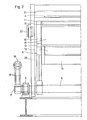
- Fig. 2 shows the closer structure of the shaft 5 and the upper knife 4 and the collar opener 6 in the left partial view.
- the shaft 5 is connected to the scissor stand via the bearing 9.
- a lever arm 10 is coupled in a rotationally fixed manner to the shaft 5.
- the free end 11 of the lever arm 10 is angled away from the roller block 2 12 (see also FIG. 1), whereby the lever arm 10 is adapted to the curvature of the roller table 7.
- a guide roller 13 is mounted on the lever arm 10 so as to be rotatable near it. Near the guide roller 13, the opening chisel 14 of the collar opener 6 is attached between the latter and the shaft 5.
- a hold-down roller 15 is attached to the free end 11 of the lever arm 10.
- a guide plate 16 is positioned between the guide roller 13 and the hold-down roller 15.
- a lever arm 18 is wedged on the shaft end 17 of the shaft 5 so that it cannot rotate.
- an adjustment drive 19 engages (see also FIG. 1).
- the opening chisel 14, the guide roller 13, the hold-down roller 15 and the guide plate 16 can be pivoted via the lever arm 18, the shaft 5 and the lever arm 10.
- the swivel range is limited on the one hand by the rolled strip coil 1 and on the other hand by the roller table 7.
- a lever arm 20 is rotatably mounted relative to the shaft 5.
- the lower knife carrier 21 which holds the lower knife 4 is fastened.
- a pull or push rod 22 is mounted on the lever arm 20 and is connected to an adjusting drive 24 via a lever arm angular gear 23 (see FIG. 1).
- the adjustment drives 19, 24 are also provided twice, in order to ensure that the scissor system functions reliably in the event of a failure of an adjustment drive.
- the lever arm angle gear 23 is rotatably coupled to the lever arm angle gear, not shown, on the right side.
- a coil carriage 25 conveys the rolled strip coil 1 to the roller block 2 and sets it down on this.
- the opening chisel 14 of the coil opener 6 is pivoted via the adjustment drives 19 against the circumference of the rolled strip bundle 1.
- the rolled strip coil 1 is set in rotation against its winding direction by drives, not shown, via the support and drive rollers 2 ', 2 ".
- the beginning of the strip comes into contact with the rolled strip coil 1 during the rotation Area of the opening chisel 14, it engages behind the beginning of the strip and derives it from the rolled strip bundle 1. While the rolled strip bundle 1 is being unwound, the bundle opener 6, driven by the adjustment drives 19, swings away from the rolled strip bundle 1 towards the roller table 7.
- the swivel speed and the tape unwinding speed are coordinated so that the beginning of the tape always remains between the guide roller 13 and the hold-down roller 15 during the pivoting movement of the coil opener 6.
- the guide plate 16 ensures that the beginning of the collar cannot move between the guide roller 13 and the hold-down roller 15 through to the rolled strip coil 1.
- the upper knife 4 is raised again.
- the deflector plate 26 is pivoted out of the area of the scrap bucket 27. In this position, the scrap bucket can optionally be lifted out of its trough and emptied.
- the rolled strip coil 1 is further unwound until the beginning of the strip has reached the end of the inspection roller table. Now the inside of the rolled strip lying open on the inspection roller table 8 can be inspected. Thereupon, by the support and drive rollers 2 ', 2 "driving the rolled strip bundle 1 in its winding direction, the rolled strip bundle 1 is rewound transported away from the coil carriage 25 and replaced by a further rolled strip bundle.
- the sample piece can be removed from the inspection roller table 8, whereupon the inspection of the inside of the belt can then follow.
Landscapes
- Engineering & Computer Science (AREA)
- Mechanical Engineering (AREA)
- Winding, Rewinding, Material Storage Devices (AREA)
- Control And Other Processes For Unpacking Of Materials (AREA)
- Shearing Machines (AREA)
- Accessories And Tools For Shearing Machines (AREA)
- Replacement Of Web Rolls (AREA)
Applications Claiming Priority (2)
| Application Number | Priority Date | Filing Date | Title |
|---|---|---|---|
| DE3247705 | 1982-12-23 | ||
| DE19823247705 DE3247705A1 (de) | 1982-12-23 | 1982-12-23 | Scherenanlage mit inspektionsrollgang |
Publications (2)
| Publication Number | Publication Date |
|---|---|
| EP0114935A2 true EP0114935A2 (fr) | 1984-08-08 |
| EP0114935A3 EP0114935A3 (fr) | 1986-03-19 |
Family
ID=6181557
Family Applications (1)
| Application Number | Title | Priority Date | Filing Date |
|---|---|---|---|
| EP83109988A Withdrawn EP0114935A3 (fr) | 1982-12-23 | 1983-10-06 | Dispositif de découpe avec un dispositif de transport et d'inspection |
Country Status (4)
| Country | Link |
|---|---|
| US (1) | US4549700A (fr) |
| EP (1) | EP0114935A3 (fr) |
| JP (1) | JPS59166411A (fr) |
| DE (1) | DE3247705A1 (fr) |
Cited By (3)
| Publication number | Priority date | Publication date | Assignee | Title |
|---|---|---|---|---|
| EP0497182A1 (fr) * | 1991-01-28 | 1992-08-05 | DANIELI & C. OFFICINE MECCANICHE S.p.A. | Machine pour ébouter l'extrémité avant et pour prélever des échantillons d'un ruban enroulé en couronne |
| FR2921852A1 (fr) * | 2007-10-08 | 2009-04-10 | Siemens Vai Metals Tech Sas | Dispositif d'inspection d'une bande metallique |
| EP3067127A1 (fr) * | 2015-03-12 | 2016-09-14 | Primetals Technologies Austria GmbH | Procédé d'inspection et de test d'un rouleau bobiné de bande métallique |
Families Citing this family (14)
| Publication number | Priority date | Publication date | Assignee | Title |
|---|---|---|---|---|
| US5257748A (en) * | 1989-09-27 | 1993-11-02 | Krantz America, Inc. | Sheet winding apparatus |
| US5022597A (en) * | 1989-09-27 | 1991-06-11 | Krantz America, Inc. | Sheet winding apparatus |
| US6691544B2 (en) | 2001-08-10 | 2004-02-17 | U.S. Properties, Inc. | Method and apparatus to uncoil and dekink coiled material |
| RU2210450C1 (ru) * | 2002-04-15 | 2003-08-20 | Открытое акционерное общество "Северсталь" | Устройство для центрирования рулонного материала |
| DE10300362A1 (de) * | 2003-01-06 | 2004-07-22 | Sms Demag Ag | Verfahren und Anlage zum Walzen und anschließendem Haspeln von Metallband, insbesondere von Stahlband |
| RU2254951C1 (ru) * | 2003-12-08 | 2005-06-27 | Открытое акционерное общество "Северсталь" | Устройство для центрирования рулонного материала |
| AT501782B1 (de) * | 2005-04-21 | 2008-12-15 | Voest Alpine Ind Anlagen | Vorrichtung und verfahren zur probennahme |
| DE102011077461A1 (de) | 2011-02-23 | 2012-08-23 | Sms Siemag Ag | Vorrichtung und Verfahren zur Entnahme einer Probe von einem Coil |
| JP6307839B2 (ja) * | 2013-11-06 | 2018-04-11 | 新日鐵住金株式会社 | コイルサンプル採取方法及びコイルサンプル採取装置 |
| US10293391B2 (en) * | 2015-03-31 | 2019-05-21 | Nucor Corporation | Coil sampling stand and method of taking coil samples |
| CN105364158B (zh) * | 2015-11-26 | 2017-11-21 | 浙江华顺金属材料有限公司 | 一种打包钢带放卷剪切装置 |
| RU2663670C1 (ru) * | 2017-02-15 | 2018-08-08 | Анатолий Вячеславович Фролов | Устройство для направления движущейся с натяжением полосы |
| RU2663505C1 (ru) * | 2017-02-15 | 2018-08-07 | Владимир Николаевич Шакуров | Устройство для направления полосы |
| CN115156605A (zh) * | 2022-06-30 | 2022-10-11 | 徐州伟迈机械制造有限公司 | 金属卷材的剪板卷圆压箍一体机用压箍剪切结构 |
Family Cites Families (6)
| Publication number | Priority date | Publication date | Assignee | Title |
|---|---|---|---|---|
| BE631046A (fr) * | 1962-04-20 | |||
| US3453150A (en) * | 1966-11-04 | 1969-07-01 | Southern Lead Co | Battery salvaging apparatus |
| JPS5048289U (fr) * | 1973-08-28 | 1975-05-13 | ||
| FR2260413B1 (fr) * | 1974-02-08 | 1976-11-26 | Promecan Sisson Lehmann | |
| DE2924379A1 (de) * | 1979-06-16 | 1981-01-08 | Siemag Transplan Gmbh | Scherenanlage zum schopfen der enden und/oder zum abtrennen von probenstuecken an auf bunde gewickeltem walzband o.dgl. |
| DE3028538A1 (de) * | 1980-07-28 | 1982-02-25 | Siemag Transplan Gmbh, 5902 Netphen | Scherenanlage zum schopfen der enden und/oder zum abtrennen von probenstuecken an auf bunde gewickeltem walzband o.dgl. |
-
1982
- 1982-12-23 DE DE19823247705 patent/DE3247705A1/de active Granted
-
1983
- 1983-10-06 EP EP83109988A patent/EP0114935A3/fr not_active Withdrawn
- 1983-12-20 US US06/563,694 patent/US4549700A/en not_active Expired - Fee Related
- 1983-12-23 JP JP58242330A patent/JPS59166411A/ja active Pending
Cited By (6)
| Publication number | Priority date | Publication date | Assignee | Title |
|---|---|---|---|---|
| EP0497182A1 (fr) * | 1991-01-28 | 1992-08-05 | DANIELI & C. OFFICINE MECCANICHE S.p.A. | Machine pour ébouter l'extrémité avant et pour prélever des échantillons d'un ruban enroulé en couronne |
| FR2921852A1 (fr) * | 2007-10-08 | 2009-04-10 | Siemens Vai Metals Tech Sas | Dispositif d'inspection d'une bande metallique |
| WO2009047395A1 (fr) * | 2007-10-08 | 2009-04-16 | Siemens Vai Metals Technologies Sas | Dispositif d'inspection d'une bande métallique |
| EP3067127A1 (fr) * | 2015-03-12 | 2016-09-14 | Primetals Technologies Austria GmbH | Procédé d'inspection et de test d'un rouleau bobiné de bande métallique |
| WO2016142016A1 (fr) * | 2015-03-12 | 2016-09-15 | Primetals Technologies Austria GmbH | Dispositif d'inspection et d'échantillonnage d'un ruban de bande métallique enroulé |
| EP3067127B1 (fr) | 2015-03-12 | 2019-10-09 | Primetals Technologies Austria GmbH | Procédé d'inspection et de test d'un rouleau bobiné de bande métallique |
Also Published As
| Publication number | Publication date |
|---|---|
| US4549700A (en) | 1985-10-29 |
| JPS59166411A (ja) | 1984-09-19 |
| DE3247705A1 (de) | 1984-07-05 |
| DE3247705C2 (fr) | 1987-10-22 |
| EP0114935A3 (fr) | 1986-03-19 |
Similar Documents
| Publication | Publication Date | Title |
|---|---|---|
| EP0114935A2 (fr) | Dispositif de découpe avec un dispositif de transport et d'inspection | |
| EP1100643B1 (fr) | Procede et dispositif pour separer transversalement des rubans ou des toles dans la ligne de laminage ou de transport | |
| EP0044923B1 (fr) | Unité de cisaillage pour ébouter un feuillard enroulé en couronne et/ou pour en prélever des échantillons | |
| DE69814882T2 (de) | Kombination von 5-ht wiederaufnahme-inhibitoren und h5-ht 1b antagonisten oder partiellen agonisten | |
| DE2803572A1 (de) | Vorrichtung zum oeffnen und verschrotten von packstueckumreifungen | |
| EP1022222A2 (fr) | Dispositif pour enlever une bande de cerclage d'objets liés avec de telles bandes, spécialement des bobines | |
| DE2924379C2 (fr) | ||
| EP0545294A2 (fr) | Dispositif pour le support rotatif d'un tambour de câble | |
| DE2744717C3 (de) | Strangbrennschneidmaschine | |
| DE2917305C2 (de) | Verfahren zur Beseitigung des Vorder- und Hinterabschnitts von Walzdraht und Vorrichtung zur Durchführung des Verfahrens | |
| DE2830333C2 (de) | Vorrichtung zum lagerichtigen Transport von Bandanfängen längsgeteilter Metallbänder | |
| DE3538889A1 (de) | Streifenschneidanlage | |
| EP0958876B1 (fr) | Dispositif pour trier selon la longueur des barres coupées | |
| DE4039048A1 (de) | Vorrichtung zum aufwickeln einer kontinuierlich zugefuehrten kunststoffbahn | |
| DE2836480B2 (de) | Vorrichtung zum Aufnehmen und Drehen eines Bandbundes | |
| EP0143452A2 (fr) | Dispositif pour couper et enrouler des rubans en métal ou des bandes en métal | |
| DE3874531T2 (de) | Drahtaufwickeleinrichtung. | |
| EP2986102B1 (fr) | Dispositif de prélèvement de fourrage ensilé | |
| EP0017643A1 (fr) | Presse à ferraille | |
| DE102004040743B3 (de) | Vorrichtung und Verfahren zum Entfernen einer Schutzverpackung | |
| DE9017740U1 (de) | Ballenabtragmaschine | |
| DE1531796B1 (de) | Silo fuer Schuettgueter mit einer Mittelsaeule zur Fuellung bzw. Entleerung | |
| DE7820724U1 (de) | Vorrichtung zum lagerichtigen transport von bandanfaengen laengsgeteilter metallbaender | |
| AT255898B (de) | Schneidvorrichtung zum Durchschneiden von Rollenkopierpapier od. dgl. | |
| DE3621087A1 (de) | Vorrichtung zum beladen von schiffen mit saecken und schuettgut |
Legal Events
| Date | Code | Title | Description |
|---|---|---|---|
| PUAI | Public reference made under article 153(3) epc to a published international application that has entered the european phase |
Free format text: ORIGINAL CODE: 0009012 |
|
| 17P | Request for examination filed |
Effective date: 19831021 |
|
| AK | Designated contracting states |
Designated state(s): AT BE DE FR GB IT NL SE |
|
| PUAL | Search report despatched |
Free format text: ORIGINAL CODE: 0009013 |
|
| STAA | Information on the status of an ep patent application or granted ep patent |
Free format text: STATUS: THE APPLICATION HAS BEEN WITHDRAWN |
|
| AK | Designated contracting states |
Kind code of ref document: A3 Designated state(s): AT BE DE FR GB IT NL SE |
|
| 18W | Application withdrawn |
Withdrawal date: 19851218 |
|
| RIN1 | Information on inventor provided before grant (corrected) |
Inventor name: GANSEUER, HORST |