EP0114946B1 - Arme portative automatique avec verrouillage fixe de culasse, pour munition à impulsion de projectile extrêmement elevée - Google Patents
Arme portative automatique avec verrouillage fixe de culasse, pour munition à impulsion de projectile extrêmement elevée Download PDFInfo
- Publication number
- EP0114946B1 EP0114946B1 EP83110724A EP83110724A EP0114946B1 EP 0114946 B1 EP0114946 B1 EP 0114946B1 EP 83110724 A EP83110724 A EP 83110724A EP 83110724 A EP83110724 A EP 83110724A EP 0114946 B1 EP0114946 B1 EP 0114946B1
- Authority
- EP
- European Patent Office
- Prior art keywords
- breech
- tube
- carrier
- spring
- head
- Prior art date
- Legal status (The legal status is an assumption and is not a legal conclusion. Google has not performed a legal analysis and makes no representation as to the accuracy of the status listed.)
- Expired
Links
- 238000010304 firing Methods 0.000 claims description 13
- 230000000694 effects Effects 0.000 claims description 8
- 238000006073 displacement reaction Methods 0.000 claims description 3
- 238000000034 method Methods 0.000 abstract description 11
- 239000007789 gas Substances 0.000 description 37
- 210000001520 comb Anatomy 0.000 description 7
- 230000001133 acceleration Effects 0.000 description 4
- 230000006835 compression Effects 0.000 description 3
- 238000007906 compression Methods 0.000 description 3
- NIOPZPCMRQGZCE-WEVVVXLNSA-N 2,4-dinitro-6-(octan-2-yl)phenyl (E)-but-2-enoate Chemical compound CCCCCCC(C)C1=CC([N+]([O-])=O)=CC([N+]([O-])=O)=C1OC(=O)\C=C\C NIOPZPCMRQGZCE-WEVVVXLNSA-N 0.000 description 2
- 238000010586 diagram Methods 0.000 description 2
- 238000000926 separation method Methods 0.000 description 2
- 206010059875 Device ineffective Diseases 0.000 description 1
- 230000000903 blocking effect Effects 0.000 description 1
- 239000000872 buffer Substances 0.000 description 1
- 210000000078 claw Anatomy 0.000 description 1
- 230000006378 damage Effects 0.000 description 1
- 230000003111 delayed effect Effects 0.000 description 1
- 230000005764 inhibitory process Effects 0.000 description 1
- 238000003780 insertion Methods 0.000 description 1
- 230000037431 insertion Effects 0.000 description 1
- 230000000149 penetrating effect Effects 0.000 description 1
- 239000000843 powder Substances 0.000 description 1
- 239000003380 propellant Substances 0.000 description 1
- 230000000717 retained effect Effects 0.000 description 1
- 238000007789 sealing Methods 0.000 description 1
- 230000035939 shock Effects 0.000 description 1
Images
Classifications
-
- F—MECHANICAL ENGINEERING; LIGHTING; HEATING; WEAPONS; BLASTING
- F41—WEAPONS
- F41A—FUNCTIONAL FEATURES OR DETAILS COMMON TO BOTH SMALLARMS AND ORDNANCE, e.g. CANNONS; MOUNTINGS FOR SMALLARMS OR ORDNANCE
- F41A5/00—Mechanisms or systems operated by propellant charge energy for automatically opening the lock
- F41A5/18—Mechanisms or systems operated by propellant charge energy for automatically opening the lock gas-operated
-
- F—MECHANICAL ENGINEERING; LIGHTING; HEATING; WEAPONS; BLASTING
- F41—WEAPONS
- F41A—FUNCTIONAL FEATURES OR DETAILS COMMON TO BOTH SMALLARMS AND ORDNANCE, e.g. CANNONS; MOUNTINGS FOR SMALLARMS OR ORDNANCE
- F41A15/00—Cartridge extractors, i.e. devices for pulling cartridges or cartridge cases at least partially out of the cartridge chamber; Cartridge ejectors, i.e. devices for throwing the extracted cartridges or cartridge cases free of the gun
- F41A15/12—Cartridge extractors, i.e. devices for pulling cartridges or cartridge cases at least partially out of the cartridge chamber; Cartridge ejectors, i.e. devices for throwing the extracted cartridges or cartridge cases free of the gun for bolt-action guns
- F41A15/14—Cartridge extractors, i.e. devices for pulling cartridges or cartridge cases at least partially out of the cartridge chamber; Cartridge ejectors, i.e. devices for throwing the extracted cartridges or cartridge cases free of the gun for bolt-action guns the ejector being mounted on or within the bolt; Extractors per se
-
- F—MECHANICAL ENGINEERING; LIGHTING; HEATING; WEAPONS; BLASTING
- F41—WEAPONS
- F41A—FUNCTIONAL FEATURES OR DETAILS COMMON TO BOTH SMALLARMS AND ORDNANCE, e.g. CANNONS; MOUNTINGS FOR SMALLARMS OR ORDNANCE
- F41A3/00—Breech mechanisms, e.g. locks
- F41A3/12—Bolt action, i.e. the main breech opening movement being parallel to the barrel axis
- F41A3/14—Rigid bolt locks, i.e. having locking elements rigidly mounted on the bolt or bolt handle and on the barrel or breech-housing respectively
- F41A3/16—Rigid bolt locks, i.e. having locking elements rigidly mounted on the bolt or bolt handle and on the barrel or breech-housing respectively the locking elements effecting a rotary movement about the barrel axis, e.g. rotating cylinder bolt locks
- F41A3/26—Rigid bolt locks, i.e. having locking elements rigidly mounted on the bolt or bolt handle and on the barrel or breech-housing respectively the locking elements effecting a rotary movement about the barrel axis, e.g. rotating cylinder bolt locks semi-automatically or automatically operated, e.g. having a slidable bolt-carrier and a rotatable bolt
-
- F—MECHANICAL ENGINEERING; LIGHTING; HEATING; WEAPONS; BLASTING
- F41—WEAPONS
- F41A—FUNCTIONAL FEATURES OR DETAILS COMMON TO BOTH SMALLARMS AND ORDNANCE, e.g. CANNONS; MOUNTINGS FOR SMALLARMS OR ORDNANCE
- F41A5/00—Mechanisms or systems operated by propellant charge energy for automatically opening the lock
- F41A5/18—Mechanisms or systems operated by propellant charge energy for automatically opening the lock gas-operated
- F41A5/26—Arrangements or systems for bleeding the gas from the barrel
- F41A5/28—Adjustable systems
Definitions
- the invention relates, according to the preamble of claim 1, to an automatic handgun with a rigidly locked breech for ammunition with an extremely high projectile impulse, the weapon being designed as a recoil loader, which is supported by a spring and brake system on the weapon housing, and is mounted on the barrel rigidly lockable, slidably guided in the weapon housing and supported on a closing spring, which carries locking members arranged on the barrel locking members and disengageable locking members and a control cam and follower device for engaging and disengaging the locking members in the pre and return movements of the closure.
- Such a weapon is essentially known from FR-A-2 256 391. It is assumed that even in this known weapon with a rigidly locked breech there must be any control cams which bring about the unlocking and locking of the breech. This document does not contain any details about the closure.
- a breech for automatic firearms which comprises a breech slide which is displaceably guided in the weapon housing and a breech block which is longitudinally displaceable relative to the breech block and which carries locking members which can be brought into and out of engagement with locking members arranged on the tube, and control cams and follower means for engaging and disengaging the locking members during the forward and return movements of the closure, and wherein the means for disengaging the locking members arranged on the tube and on the closure head during the return movement of the closure between Closure carrier and closure head is arranged.
- the closure carrier is moved back by a plunger, the closure carrier executing a relative movement with respect to the closure body.
- the closure carrier is thus moved by a separate drive and not by braking the return movement of the tube relative to the tube.
- the description of the application of the closure relates to a gas pressure charger.
- a two-part breech is used in gas pressure loaders which has a breech carrier and a breech head which is displaceable longitudinally with respect to the breech carrier and which carries locking members which can be brought into and out of engagement with corresponding locking members on the barrel of the weapon by the relative movement between the breech carrier and breech head.
- the gas piston acts on the closure carrier and gives the closure carrier the relative movement to the closure head required to unlock the closure.
- the unlocking process usually takes place only after the projectile has left the barrel of the weapon, so that the shooter has to catch the entire projectile impulse via the rigidly locked breech. Therefore, it is only possible to fire ammunition with a relatively small projectile pulse with known handguns.
- Handguns with rigidly locked breeches which are designed as recoil loaders, are essentially only known in the form of pistols.
- the barrel is initially carried along by the one-piece breech until a lateral displacement of the barrel or breech takes place via control cams mounted in the housing, as a result of which locking lugs attached to the breech disengage from the barrel, as is the case with the Colt Government pistol.
- the barrel is unsprung and is brought back into the firing position by the bouncing breech when the weapon is loaded. With this type of weapon, the barrel hits abutments undamped, which stop its return movement and unlock the barrel and breech.
- the recoil pulse transmitted to the weapon is so great that such an arrangement is completely unsuitable for ammunition with an extremely high projectile pulse.
- the invention has for its object to design an automatic handgun of the type described above so that the force transmitted by the projectile impulse to the weapon housing and to be absorbed by the shooter is almost uniform and strong force peaks are avoided in any case.
- the closure comprises a closure carrier which is supported on the closing spring and a closure head which is displaceable longitudinally relative to the closure carrier, that the device for disengaging the on the tube and on Locking members arranged locking members is arranged during the return movement of the closure between the closure carrier and closure head that the relative movement required for unlocking the closure between the closure carrier and the closure head is caused exclusively by braking the tube, and that the spring and brake system and the closing spring are so coordinated that the tube is brought to a standstill during its backward movement exclusively by the spring and brake system, and that the closure reaches its rear end position at a speed at which no significant force peaks occur.
- the invention thus makes use of the known principle of the recoil loader with a rigidly locked, two-part breech, although this principle has hitherto only been used with stationary machine guns, because the recoil pulse transmitted to the weapon housing is so great that it cannot be expected to be picked up by a gunner can, so that the application of this principle to a handgun, which is designed to fire ammunition with extremely high projectile impulse, must appear senseless from the outset.
- the relative movement between the breech carrier and the breech head is not effected by control cams arranged in the weapon housing, but by means which are arranged between the breech carrier and the breech head.
- the closure head with a cylindrical extension in a bore of the closure carrier is rotatably supported about its longitudinal axis and by a bolt inserted into a diagonal bore of the extension, which engages in an oblique slot of the closure carrier and thereby results in a longitudinal displacement of the closure head relative to the Breech carrier also causes rotation of the breech head, held in the breech carrier, which pin in turn is in position by the firing pin axially penetrating in the breech head is secured.
- Such training is both particularly simple and very stable, as is required for a handgun exposed to very high loads, which is intended for ammunition with an extremely high projectile impulse.
- force peaks can also result from the fact that the tube and / or the breech have a considerable speed at the end of their return movement and then hit buffers which are attached to the gun housing for this purpose quite hard. Since these force peaks are disturbing, the system described above must be designed so that the tube and closure are almost completely braked when they reach the intended end positions, so that the forces required for the complete braking necessary before the reversal of motion are not appear as disturbing force peaks. As a result, the system according to the invention must be matched very precisely to the projectile impulse of the type of ammunition provided.
- a further embodiment of the invention provides that the breech carrier is additionally operatively connected to a gas pressure charging device which can be changed in its effect, in particular can be switched off.
- Such a gas pressure charging device can have, in a manner known per se, a cylinder connected to the barrel via a bore and a piston which is displaceably mounted in the cylinder and acts on the breech carrier, which then gives the breech carrier an additional acceleration when firing ammunition with a low projectile impulse so that the loading process takes place takes place properly.
- the arrangement can, for example, be such that the gas pressure loading device which starts somewhat delayed as a result of the gas flow processes no longer has any significant effect when ammunition with a high projectile impulse is used, in which support by the gas pressure loading device is not required .
- shut-off valve is also to be understood as a valve which not only either completely releases or completely shuts off the connection between the tube and the cylinder, but which can also be brought into intermediate positions in which it restricts this connection to a greater or lesser extent .
- a valve can easily be designed so that it can be adjusted to different types of ammunition.
- the shut-off valve could be formed by a slide arranged in the cylinder, which more or less closes or opens the bore opening into the cylinder wall. Such a slide can be easily adjusted from the side facing away from the piston without any sealing problems occurring because the slide, like the piston, can be tightly guided on the side of the bore in the cylinder facing away from the piston.
- shut-off valve does not have to be adjusted manually to the different types of ammunition, but is instead automatically brought into a position which is adapted to the projectile impulse of the respective ammunition.
- This not only simplifies the use of the firearm according to the invention, but above all it ensures that when the ammunition type is changed, an adjustment of the shut-off valve is not forgotten, and as a result of such a forgetting, if the projectile pulse is too low, it does not lead to loading inhibitions or if it is too strong Projectile impulse can not lead to significant mistakes or even injuries due to a hard setback.
- This automatic adjustment of the shut-off valve is achieved in the preferred embodiment of the invention in that the position of the shut-off valve is controlled by an inertial mass movably mounted in relation to the tube and loaded by a spring, in such a way that, due to the coordination of the size of the mass and the force of the spring on the return behavior of the pipe, the mass only follow a slow return movement of the pipe, such as occurs when firing ammunition with a small projectile impulse, while keeping the valve open, while the mass remains behind the pipe and all the more to close off the bore causes the faster the return movement of the pipe takes place with a larger projectile impulse.
- the shut-off valve can be formed by a slide arranged in the cylinder, and this slide can directly form the inertial mass causing the valve control and can be loaded by a spring arranged in the cylinder, which strives to To hold the slide in a position at the rear in relation to the firing direction, in which the slide releases the bore.
- the slide is designed as a sleeve which has an annular groove on its circumference, in the area of which the bore opens when the slide is in its rest position, and which is connected to the interior of the sleeve via radial bores. This design of the slide ensures that the forces exerted by the gas pressure on the sleeve compensate in the axial direction, and the position of the slide is independent of the gas pressure prevailing in the cylinder.
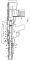
- the barrel 1 of the rifle shown in FIG. 1 is displaceably mounted in the weapon housing 2 in its longitudinal direction and is supported by a spring 6 and a system 6 containing a friction brake 5 on an abutment 8 containing disc springs 7.
- a breech which consists of a breech slide 9 which is displaceable in its longitudinal direction in the weapon housing 2 and a breech head 10 which can be rigidly locked with the rear end of the tube 1 and rotates about its longitudinal axis.
- the breech carrier 9 is loaded by a closing spring 11 which is supported at the rear end of the weapon housing 2.
- the closure carrier 9 has on its underside an extension 12 in which there is a bore 13 which is concentric with the axis of the tube 1 and into which the closure head 10 engages.
- the closure head 10 has radially projecting, axially parallel locking combs 14 which, when the closure is locked, place corresponding locking combs 15 at the rear end of the tube 1.
- the combs 14 on the closure head face gaps between the locking combs 15 on the tube 1 and vice versa.
- a bolt 16 which is arranged at right angles to the longitudinal axis and which projects at one end over the circumference of the closure head 10.
- This end forms a pin 17 which engages in a slot 18 which extends obliquely to the surface lines of the closure head 10 or the bore 13 in the closure carrier 9. Due to the engagement of the pin 17 in the oblique slot 18, there is a positive connection between the closure head 10 and the shoulder 12 on the closure carrier 9, which permits a limited axial movement of the closure head 10 relative to the closure carrier 9 with simultaneous rotation.
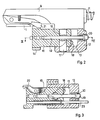
- the bolt 16 is held in the breech head 10 by the firing pin 19 which is inserted into bores of the breech carrier 9 and the breech head 10 which are concentric with the axis of the tube 1 and is held at its rear end by an inserted bracket 20.
- 2 and 3 reveal further details of the closure and components stored therein, namely a lever 21 for locking the closure head 10 in the unlocked state, an extractor claw 22 and a spring-loaded ejector rod 23.
- the special feature of the recoil drawer described is the separation of the closure carrier 9 from the tube 1 with a differential speed starting at 0, whereby the screwing of the closure head out of the lock is extended in time and thus a completely shock-free unlocking is ensured.
- the existing spring systems can be tuned so that the ammunition with the largest projectile impulse, i.e. if there is no gas pressure support, the tube reverses its direction of movement before it hits a stop that mechanically limits the return path, while the breech closes its rear end position with a Speed reached at which a perfect loading is still guaranteed, but no significant force peaks occur. This means that the entire loading process can be controlled so that the projectile pulse is distributed very evenly over a long period of time and the shooter is able to fire ammunition with an extremely high projectile pulse.
- the rifle has an additional gas pressure loading device.
- This gas pressure charging device comprises in a conventional manner a cylinder 31 which is attached to the top of the tube 1 and communicates with the interior of the tube via a radial bore 32.
- a piston 33 is slidably mounted, which carries at its rear end with respect to the firing direction a piston rod 44 which projects from the bottom of the cylinder 31 and faces the end face of the breech carrier 9.
- the piston rod 34 is surrounded by a helical compression spring 35 which tends to hold the piston 33 in the front position shown in FIG. 1.
- a valve 37 which in the illustrated embodiment is formed by an externally actuated rotary valve which either connects the radial bore 32 to the interior 36 of the cylinder 31 or blocks the radial bore 32. This valve 37 therefore makes it possible, when firing ammunition with the extremely high projectile impulse, to render the gas pressure loading device ineffective by blocking the radial bore 32.
- valve 37 can be opened so that the breech carrier 9 is given an additional acceleration by the gas pressure acting on the piston 33, which ensures that the breech 9 is unlocked properly and reaches its rear end position, as is necessary for a perfect loading process, even if the speed given as a result of the recoil to the tube 1 and thus the closure 9 would not be sufficient to bring about a perfect separation between the closure and the tube or even to bring the closure into its rear end position.
- the advantage of the design of the rifle according to the invention is fully retained, namely that the unlocking of the breech is initiated completely smoothly by the slowly increasing relative speed of the breech 9 relative to the tube 1 as a result of the braking of the tube 1 and then increasingly by the effective gas pressure is only accelerated, without the occurrence of any pressure peaks.
- valve 37 need not only have two positions in which the gas pressure charging system is either switched off or in effect, but that several positions are possible in which bores of different cross-sections are released in order to thereby open the cylinder 31 throttling gas flow more or less and thereby adapt the effect of the gas pressure loading device to several different types of ammunition.
- a valve has the disadvantage, however, that it must be set manually to the respective type of ammunition, so that there is a possibility that the correct setting is omitted for a variety of reasons Embodiment automatically adjusts to the respective type of ammunition and therefore ensures that such errors are avoided when handling the rifle.
- a sleeve-shaped slide 44 is slidably mounted in its longitudinal direction in the cylinder 31.
- This slide 44 is loaded at its front end with respect to the firing direction by a helical compression spring 45 arranged in the cylinder 31, the slide 44 of which compresses the slide 44 opposite end is supported on a screwed onto the front end of the cylinder 31 cover 45.
- the spring 45 endeavors to hold the slide 44 in a rest position in which its rear end abuts a stop 47 which is formed by a pin projecting radially into the cylinder 31.
- the slide 44 has an annular groove 48 on its circumference, in the area of which the bore 32 connecting the tube 1 to the cylinder 31 opens when the slide 44 assumes its rest position, which is defined by the abutment on the stop 47.
- the annular groove 48 is connected via radial bores 49 to the interior of the sleeve-shaped slide 44 so that powder gases from the tube 1 can enter the cylinder 31 through the bore 32, the annular groove 48 and the radial bores 49.
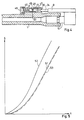
- curves 51 and 52 illustrate the return movement of the tube closure system in the case of ammunition with a weak or strong projectile impulse.
- the ordinate of the diagram according to FIG. 5 indicates the path s and the abscissa the time t during which the path s marked by the ordinate is covered. It can be readily seen that the movement of the pipe closure system represented by curve 52 occurs much faster with a strong projectile impulse and therefore also with greater acceleration than the return movement of the pipe closure system with weak projectile impulse which occurs through the curve 51 is illustrated.
- the dash-dotted curve 53 in FIG. 5 illustrates the movement of the system formed by the slide 44 and the helical compression spring 45.
- This system is tuned in such a way that when the projectile pulse is weak, the slide 44 follows the return movement of the pipe closure system, so that the slide 44 maintains its position with respect to this system and the bore 32 in the region of the groove 49 during the entire return movement of the slide 44 and propellant gases can freely enter the cylinder 31.
- the gas pressure charging device is then fully effective in the manner described above.
- the mass of the slide 44 and the force of the spring 45 can be selected so that in connection with the design of the control surfaces on the slide 44 such an amount of gas is admitted into the cylinder 31 that over a wide range
- the impulse exerted by the recoil and the gas pressure on the pipe closure system or the closure is always sufficient to carry out the loading process properly, but without the pulse energy being substantially greater than the energy required for the loading process, so that none there is a significant surplus of energy that would have to be destroyed and led to unbearable peaks in energy.
- the invention is not limited to the exemplary embodiments shown, but deviations are possible without leaving the scope of the invention.
- devices other than valves to influence the action of the gas pressure charging system, for example devices for braking or even locking the piston actuated by the gas pressure.
Landscapes
- Engineering & Computer Science (AREA)
- General Engineering & Computer Science (AREA)
- Aiming, Guidance, Guns With A Light Source, Armor, Camouflage, And Targets (AREA)
- Portable Nailing Machines And Staplers (AREA)
- Emergency Lowering Means (AREA)
- Ladders (AREA)
- Buckles (AREA)
Claims (8)
Priority Applications (1)
| Application Number | Priority Date | Filing Date | Title |
|---|---|---|---|
| AT83110724T ATE37949T1 (de) | 1982-11-30 | 1983-10-27 | Automatische handfeuerwaffe mit starr verriegeltem verschluss fuer munition mit extremem geschossimpuls. |
Applications Claiming Priority (2)
| Application Number | Priority Date | Filing Date | Title |
|---|---|---|---|
| DE3244315A DE3244315C2 (de) | 1982-11-30 | 1982-11-30 | Automatische Handfeuerwaffe mit starr verriegeltem Verschluß für Munition mit extrem hohem Geschoßimpuls |
| DE3244315 | 1982-11-30 |
Publications (3)
| Publication Number | Publication Date |
|---|---|
| EP0114946A2 EP0114946A2 (fr) | 1984-08-08 |
| EP0114946A3 EP0114946A3 (en) | 1986-07-02 |
| EP0114946B1 true EP0114946B1 (fr) | 1988-10-12 |
Family
ID=6179465
Family Applications (1)
| Application Number | Title | Priority Date | Filing Date |
|---|---|---|---|
| EP83110724A Expired EP0114946B1 (fr) | 1982-11-30 | 1983-10-27 | Arme portative automatique avec verrouillage fixe de culasse, pour munition à impulsion de projectile extrêmement elevée |
Country Status (5)
| Country | Link |
|---|---|
| US (1) | US4635530A (fr) |
| EP (1) | EP0114946B1 (fr) |
| AT (1) | ATE37949T1 (fr) |
| CA (1) | CA1226459A (fr) |
| DE (1) | DE3244315C2 (fr) |
Families Citing this family (31)
| Publication number | Priority date | Publication date | Assignee | Title |
|---|---|---|---|---|
| US5353681A (en) * | 1993-03-16 | 1994-10-11 | Sugg Ronald E | Recoil dampening device for large caliber weapons |
| US5640794A (en) * | 1995-07-07 | 1997-06-24 | Fn Manufacturing, Inc. | Fire control mechanism for an automatic pistol |
| RU2110745C1 (ru) * | 1997-06-05 | 1998-05-10 | Открытое Акционерное Общество "Ижмаш" | Автоматическое оружие |
| DE19903322B4 (de) | 1999-01-28 | 2005-03-17 | Heckler & Koch Gmbh | Selbstlade-Handfeuerwaffe mit einem beweglichen Verschluß mit Verriegelungswarzen |
| DE19903327B4 (de) | 1999-01-28 | 2004-08-12 | Heckler & Koch Gmbh | Verschlußvorrichtung für eine Handfeuerwaffe |
| AUPQ598700A0 (en) * | 2000-03-02 | 2000-05-18 | Vader Pty Ltd | Weapon |
| US7311032B2 (en) * | 2002-09-04 | 2007-12-25 | Heckler & Koch, Gmbh | Firearms with gas pressure loading mechanisms |
| US7237469B2 (en) * | 2002-09-04 | 2007-07-03 | Heckler & Koch, Gmbh | Firearms having a locked breech |
| ITMI20041594A1 (it) * | 2004-08-03 | 2004-11-03 | Beretta Armi Spa | Arma da fuoco individuale con dispositivo di riarmo migliorato |
| US7448307B1 (en) * | 2005-09-30 | 2008-11-11 | Vesselin Dafinov | Gas operated semi-automatic rifle |
| DE102007034672A1 (de) | 2007-07-25 | 2009-01-29 | Heckler & Koch Gmbh | Verschlussbauteil, Verschlussanordnung und Verriegelungseinrichtung für eine Waffe |
| DE102007034671A1 (de) | 2007-07-25 | 2009-01-29 | Heckler & Koch Gmbh | Rohrführungsanordnung, Waffenrohranordnung und Bremsfederanordnung |
| US8210089B2 (en) | 2008-07-01 | 2012-07-03 | Adcor Industries, Inc. | Firearm having an indirect gas impingement system |
| US9261314B1 (en) | 2010-07-19 | 2016-02-16 | Jason Stewart Jackson | Sleeve piston for actuating a firearm bolt carrier |
| US9488423B2 (en) | 2011-01-14 | 2016-11-08 | Arm West, Llc | Firearm systems and methods |
| US8746126B2 (en) * | 2011-11-23 | 2014-06-10 | Jing Zheng | Annular piston system for rifles |
| US8997620B2 (en) | 2012-03-09 | 2015-04-07 | Adcor Industries, Inc. | Handle assembly for charging a direct gas impingement firearm |
| WO2014105534A2 (fr) * | 2012-12-17 | 2014-07-03 | Tactical Arms Holdings Co., Llc | Améliorations apportées à un système à gaz et au mécanisme de chargement d'une arme à feu |
| US20150176943A1 (en) * | 2013-05-13 | 2015-06-25 | Giulio Iervolino | Rifle System |
| US9021935B1 (en) * | 2013-12-05 | 2015-05-05 | George Kellgren | Hollow hammer with downward ejecting chamber for rifle |
| AR104686A1 (es) * | 2015-05-22 | 2017-08-09 | Arm West Llc | Sistemas y métodos de arma de fuego |
| US11156425B2 (en) | 2018-01-22 | 2021-10-26 | Vojtech Dvorak | Composite striker for firearm simulator |
| US11035636B2 (en) | 2019-07-26 | 2021-06-15 | Smith & Wesson Inc. | Shotgun ammunition feeding system |
| US11306995B2 (en) | 2019-08-06 | 2022-04-19 | Smith & Wesson Inc. | Shotgun configuration |
| US11326845B2 (en) * | 2019-08-13 | 2022-05-10 | Smith & Wesson Inc. | Firearm having reciprocable breech cover |
| US11022386B2 (en) | 2019-08-15 | 2021-06-01 | Smith & Wesson Inc. | Firearm breech cover interlock |
| EP3800427A1 (fr) * | 2019-10-04 | 2021-04-07 | Glock Technology GmbH | Arme à feu dotée d'un éjecteur |
| DE102019131439A1 (de) * | 2019-11-21 | 2021-05-27 | Rheinmetall Waffe Munition Gmbh | Verschluss eines Waffensystems und Waffensystem mit dem Verschluss |
| US11846484B2 (en) * | 2020-12-21 | 2023-12-19 | Caracal International, Llc | Firearm with gas piston assembly |
| US11644256B2 (en) * | 2021-03-28 | 2023-05-09 | Jordan Kristomas Kennedy | System for a multi-caliber self-loading action assembly |
| DE102021005162B4 (de) | 2021-10-15 | 2025-08-28 | Heckler & Koch Gmbh | Gasabnahme |
Family Cites Families (15)
| Publication number | Priority date | Publication date | Assignee | Title |
|---|---|---|---|---|
| US3058400A (en) * | 1959-01-23 | 1962-10-16 | Remington Arms Co Inc | Compensating device for gas operated firearms |
| US3036501A (en) * | 1959-08-03 | 1962-05-29 | Olin Mathieson | Firearms control device for automatically regulating gas flow |
| US3024706A (en) * | 1959-08-24 | 1962-03-13 | Olin Mathieson | Gas operated firearm with a movable gas cylinder functioning as an inertia member |
| US2987968A (en) * | 1959-09-28 | 1961-06-13 | Olin Mathieson | Firearm gas piston with power cavity and inertia valve |
| US3171326A (en) * | 1962-03-29 | 1965-03-02 | Charles H Baker | Recoil friction brake for automatic firearms |
| US3110222A (en) * | 1962-04-05 | 1963-11-12 | Earle M Harvey | Gas assist system for recoil actuated firearms |
| US3483648A (en) * | 1968-03-01 | 1969-12-16 | Stephen Speckhart | Anti-recoil firearm |
| CH517283A (de) * | 1969-12-19 | 1971-12-31 | Oerlikon Buehrle Ag | Selbsttätige Feuerwaffe |
| CH550373A (de) * | 1972-01-18 | 1974-06-14 | Oerlikon Buehrle Ag | Einrichtung zur mehrstufigen, hydraulisch-mechanischen abbremsung der vorlaufbewegung des verschiebbaren rohres einer selbsttaetigen feuerwaffe. |
| CH556011A (de) * | 1972-08-31 | 1974-11-15 | Oerlikon Buehrle Ag | Selbsttaetige feuerwaffe. |
| FI50029C (fi) * | 1973-04-27 | 1975-11-10 | Valmet Oy | Ampuma-aseen, etenkin puoliautomaattihaulikon kaasumäntärakenteen pain eentasausventtiili. |
| CH570599A5 (fr) * | 1973-10-03 | 1975-12-15 | Oerlikon Buehrle Ag | |
| CH588061A5 (fr) * | 1973-12-28 | 1977-05-31 | Sarmac Sa | |
| DE2408446A1 (de) * | 1974-02-21 | 1975-08-28 | Karlsruhe Augsburg Iweka | Feuerwaffe, insbesondere kurzbauende handfeuerwaffe |
| DE2944859C2 (de) * | 1979-11-07 | 1983-10-13 | Mauser-Werke Oberndorf Gmbh, 7238 Oberndorf | Vor- und Rücklaufeinrichtung für eine Feuerwaffe |
-
1982
- 1982-11-30 DE DE3244315A patent/DE3244315C2/de not_active Expired
-
1983
- 1983-10-27 EP EP83110724A patent/EP0114946B1/fr not_active Expired
- 1983-10-27 AT AT83110724T patent/ATE37949T1/de not_active IP Right Cessation
- 1983-11-25 CA CA000441996A patent/CA1226459A/fr not_active Expired
-
1985
- 1985-12-04 US US06/805,401 patent/US4635530A/en not_active Expired - Lifetime
Also Published As
| Publication number | Publication date |
|---|---|
| DE3244315A1 (de) | 1984-05-30 |
| CA1226459A (fr) | 1987-09-08 |
| ATE37949T1 (de) | 1988-10-15 |
| EP0114946A3 (en) | 1986-07-02 |
| DE3244315C2 (de) | 1984-11-29 |
| EP0114946A2 (fr) | 1984-08-08 |
| US4635530A (en) | 1987-01-13 |
Similar Documents
| Publication | Publication Date | Title |
|---|---|---|
| DE3244315C2 (de) | Automatische Handfeuerwaffe mit starr verriegeltem Verschluß für Munition mit extrem hohem Geschoßimpuls | |
| EP0656518B1 (fr) | Arme à feu comportant un amortisseur de recul, en particulier arme à poing | |
| EP1147359B1 (fr) | Culasse pour arme a feu de poing | |
| CH715112A2 (de) | Federsystem zu Masseverschluss für Feuerwaffen im Pistolenkaliber. | |
| DE2413615C3 (de) | Handfeuerwaffe mit schwenkbarem VerschluBteU | |
| EP3978859A1 (fr) | Culasse cylindrique à traction directe pour armes à répétition et arme à répétition dotée d'une telle culasse | |
| DE1728051A1 (de) | Automatische Kanonc | |
| EP3488172B1 (fr) | Arme à canon, en particulier pistolet, comprenant un amortisseur de recul | |
| DE19804653C2 (de) | Großkalibrige Waffe | |
| DE2747932A1 (de) | Geschosspatrone | |
| WO2023283664A1 (fr) | Arme à feu | |
| DE2647899C2 (de) | Gasdruckbetätigte Schußwaffe | |
| DE2408446A1 (de) | Feuerwaffe, insbesondere kurzbauende handfeuerwaffe | |
| DE202006007925U1 (de) | Waffenverschlußsystem | |
| DE3871556T2 (de) | Munitionszufuehrvorrichtung fuer halbautomatische oder mittels handschieber betaetigte flinten. | |
| AT393028B (de) | Gasentnahmesystem fuer eine feuerwaffe | |
| EP0114204A2 (fr) | Arme à feu automatique à emprunt de gaz | |
| DE3919761C2 (de) | Geschütz für flüssige Treibladungen | |
| WO2021222950A1 (fr) | Système de culasse à commande par pression de gaz pour une arme à feu | |
| DE2326527A1 (de) | Verschlussanordnung | |
| DE1166052B (de) | Einsatzgeraet mit Einstecklauf zum Verschiessen von Kleinkaliber-Munition durch automatische Handfeuerwaffen, insbesondere Sturmgewehre mit Hammerzuendung | |
| DE620740C (de) | Maschinenwaffe mit motorbetriebenem und vom Antrieb abschaltbarem Verschluss | |
| DE1058408B (de) | Verschluss fuer selbsttaetige Feuerwaffe | |
| DE1553854C3 (de) | Verschluß für Handfeuerwaffen | |
| AT215861B (de) | Verschluß für selbsttätige Feuerwaffen |
Legal Events
| Date | Code | Title | Description |
|---|---|---|---|
| PUAI | Public reference made under article 153(3) epc to a published international application that has entered the european phase |
Free format text: ORIGINAL CODE: 0009012 |
|
| AK | Designated contracting states |
Designated state(s): AT BE CH FR GB IT LI NL SE |
|
| PUAL | Search report despatched |
Free format text: ORIGINAL CODE: 0009013 |
|
| AK | Designated contracting states |
Kind code of ref document: A3 Designated state(s): AT BE CH FR GB IT LI NL SE |
|
| 17P | Request for examination filed |
Effective date: 19860611 |
|
| 17Q | First examination report despatched |
Effective date: 19870309 |
|
| GRAA | (expected) grant |
Free format text: ORIGINAL CODE: 0009210 |
|
| ITF | It: translation for a ep patent filed | ||
| AK | Designated contracting states |
Kind code of ref document: B1 Designated state(s): AT BE CH FR GB IT LI NL SE |
|
| REF | Corresponds to: |
Ref document number: 37949 Country of ref document: AT Date of ref document: 19881015 Kind code of ref document: T |
|
| ET | Fr: translation filed | ||
| GBT | Gb: translation of ep patent filed (gb section 77(6)(a)/1977) | ||
| PLBE | No opposition filed within time limit |
Free format text: ORIGINAL CODE: 0009261 |
|
| STAA | Information on the status of an ep patent application or granted ep patent |
Free format text: STATUS: NO OPPOSITION FILED WITHIN TIME LIMIT |
|
| 26N | No opposition filed | ||
| PGFP | Annual fee paid to national office [announced via postgrant information from national office to epo] |
Ref country code: SE Payment date: 19901011 Year of fee payment: 8 |
|
| PGFP | Annual fee paid to national office [announced via postgrant information from national office to epo] |
Ref country code: NL Payment date: 19901031 Year of fee payment: 8 |
|
| PG25 | Lapsed in a contracting state [announced via postgrant information from national office to epo] |
Ref country code: SE Effective date: 19911028 |
|
| PG25 | Lapsed in a contracting state [announced via postgrant information from national office to epo] |
Ref country code: NL Effective date: 19920501 |
|
| NLV4 | Nl: lapsed or anulled due to non-payment of the annual fee | ||
| ITTA | It: last paid annual fee | ||
| EUG | Se: european patent has lapsed |
Ref document number: 83110724.8 Effective date: 19920510 |
|
| PGFP | Annual fee paid to national office [announced via postgrant information from national office to epo] |
Ref country code: BE Payment date: 20011023 Year of fee payment: 19 |
|
| PGFP | Annual fee paid to national office [announced via postgrant information from national office to epo] |
Ref country code: FR Payment date: 20011026 Year of fee payment: 19 |
|
| PGFP | Annual fee paid to national office [announced via postgrant information from national office to epo] |
Ref country code: GB Payment date: 20011029 Year of fee payment: 19 |
|
| PGFP | Annual fee paid to national office [announced via postgrant information from national office to epo] |
Ref country code: AT Payment date: 20011030 Year of fee payment: 19 |
|
| REG | Reference to a national code |
Ref country code: GB Ref legal event code: IF02 |
|
| PGFP | Annual fee paid to national office [announced via postgrant information from national office to epo] |
Ref country code: CH Payment date: 20020104 Year of fee payment: 19 |
|
| PG25 | Lapsed in a contracting state [announced via postgrant information from national office to epo] |
Ref country code: GB Free format text: LAPSE BECAUSE OF NON-PAYMENT OF DUE FEES Effective date: 20021027 Ref country code: AT Free format text: LAPSE BECAUSE OF NON-PAYMENT OF DUE FEES Effective date: 20021027 |
|
| PG25 | Lapsed in a contracting state [announced via postgrant information from national office to epo] |
Ref country code: LI Free format text: LAPSE BECAUSE OF NON-PAYMENT OF DUE FEES Effective date: 20021031 Ref country code: CH Free format text: LAPSE BECAUSE OF NON-PAYMENT OF DUE FEES Effective date: 20021031 Ref country code: BE Free format text: LAPSE BECAUSE OF NON-PAYMENT OF DUE FEES Effective date: 20021031 |
|
| BERE | Be: lapsed |
Owner name: *HECKLER & KOCH G.M.B.H. Effective date: 20021031 |
|
| REG | Reference to a national code |
Ref country code: CH Ref legal event code: PL |
|
| GBPC | Gb: european patent ceased through non-payment of renewal fee | ||
| PG25 | Lapsed in a contracting state [announced via postgrant information from national office to epo] |
Ref country code: FR Free format text: LAPSE BECAUSE OF NON-PAYMENT OF DUE FEES Effective date: 20030630 |
|
| REG | Reference to a national code |
Ref country code: FR Ref legal event code: ST |