EP0114959B1 - Interrupteur pour installation d'électricité comprenant des instruments électroniques - Google Patents
Interrupteur pour installation d'électricité comprenant des instruments électroniques Download PDFInfo
- Publication number
- EP0114959B1 EP0114959B1 EP83111588A EP83111588A EP0114959B1 EP 0114959 B1 EP0114959 B1 EP 0114959B1 EP 83111588 A EP83111588 A EP 83111588A EP 83111588 A EP83111588 A EP 83111588A EP 0114959 B1 EP0114959 B1 EP 0114959B1
- Authority
- EP
- European Patent Office
- Prior art keywords
- switch
- actuating element
- instruments
- instrument
- electronic
- Prior art date
- Legal status (The legal status is an assumption and is not a legal conclusion. Google has not performed a legal analysis and makes no representation as to the accuracy of the status listed.)
- Expired
Links
Images
Classifications
-
- H—ELECTRICITY
- H01—ELECTRIC ELEMENTS
- H01H—ELECTRIC SWITCHES; RELAYS; SELECTORS; EMERGENCY PROTECTIVE DEVICES
- H01H9/00—Details of switching devices, not covered by groups H01H1/00 - H01H7/00
- H01H9/02—Bases, casings, or covers
-
- G—PHYSICS
- G01—MEASURING; TESTING
- G01D—MEASURING NOT SPECIALLY ADAPTED FOR A SPECIFIC VARIABLE; ARRANGEMENTS FOR MEASURING TWO OR MORE VARIABLES NOT COVERED IN A SINGLE OTHER SUBCLASS; TARIFF METERING APPARATUS; MEASURING OR TESTING NOT OTHERWISE PROVIDED FOR
- G01D7/00—Indicating measured values
-
- G—PHYSICS
- G12—INSTRUMENT DETAILS
- G12B—CONSTRUCTIONAL DETAILS OF INSTRUMENTS, OR COMPARABLE DETAILS OF OTHER APPARATUS, NOT OTHERWISE PROVIDED FOR
- G12B9/00—Housing or supporting of instruments or other apparatus
- G12B9/02—Casings; Housings; Cabinets
-
- H—ELECTRICITY
- H01—ELECTRIC ELEMENTS
- H01H—ELECTRIC SWITCHES; RELAYS; SELECTORS; EMERGENCY PROTECTIVE DEVICES
- H01H9/00—Details of switching devices, not covered by groups H01H1/00 - H01H7/00
- H01H9/18—Distinguishing marks on switches, e.g. for indicating switch location in the dark; Adaptation of switches to receive distinguishing marks
- H01H9/181—Distinguishing marks on switches, e.g. for indicating switch location in the dark; Adaptation of switches to receive distinguishing marks using a programmable display, e.g. LED or LCD
Definitions
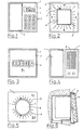
- reference numeral 2 designates the actuating element located in the center of the front switch frame in the form and size of a switch rocker or button that conforms to the standards.
- a scale 6 of a clock, in particular a time switch, with the pointers 7 runs in a ring around the actuating element 2.
- the scale 6 of this clock is expediently covered by a cover glass.
- the setting elements can be arranged concealed on the side or on the back. In the latter case, it is necessary to remove the actuating element 2 for programming or setting the clock.
- FIG. 3 an electrical switch is visible with an integrated operating time counter.
- Reference numeral 1 denotes the switch frame.
- the actuating element 2 in the form of a rocker switch is crystal-clear and gives a clear view of the dial of the digitally displaying operating time counter with a counter 8.
- the front surface of the actuating element 2 is provided with only one cutout for the counter 8 and the remaining surface of the actuating element 2 can be designed freely.
- a switch frame 1 is visible, with a two-part device device arranged there on the front.
- the reference number 9 indicates a sensor for ultrasound or infrared room monitoring. It is also contemplated that, instead of such a sensor, a loudspeaker and / or a microphone is installed on the surface half 3 for acoustic room monitoring or an intercom.
- the signals of such electronic device devices can be transmitted via the existing line network, in particular in the so-called time, frequency or pulse multiplex method. However, it is also possible to carry out separate line installations via the existing pipe network for the transmission of such signals.
- an electronic device device in particular a time switch, directly mechanically actuates the switch, in the actuating element 2 of which it is installed, by a mechanical switching element, which is controlled by the device device, between the actuating element 2 and a stationary switch acts point and switches the actuator 2 in its switching position.
Landscapes
- Physics & Mathematics (AREA)
- General Physics & Mathematics (AREA)
- Electric Clocks (AREA)
Claims (5)
Applications Claiming Priority (2)
| Application Number | Priority Date | Filing Date | Title |
|---|---|---|---|
| DE8234397U | 1982-12-08 | ||
| DE8234397U DE8234397U1 (de) | 1982-12-08 | 1982-12-08 | Elektrischer Schalter für die Rauminstallation mit elektronischen Geräteeinrichtungen |
Publications (3)
| Publication Number | Publication Date |
|---|---|
| EP0114959A2 EP0114959A2 (fr) | 1984-08-08 |
| EP0114959A3 EP0114959A3 (en) | 1987-04-15 |
| EP0114959B1 true EP0114959B1 (fr) | 1989-07-26 |
Family
ID=6746289
Family Applications (1)
| Application Number | Title | Priority Date | Filing Date |
|---|---|---|---|
| EP83111588A Expired EP0114959B1 (fr) | 1982-12-08 | 1983-11-19 | Interrupteur pour installation d'électricité comprenant des instruments électroniques |
Country Status (2)
| Country | Link |
|---|---|
| EP (1) | EP0114959B1 (fr) |
| DE (1) | DE8234397U1 (fr) |
Families Citing this family (8)
| Publication number | Priority date | Publication date | Assignee | Title |
|---|---|---|---|---|
| JPH0330984Y2 (fr) * | 1985-01-09 | 1991-07-01 | ||
| JP2668212B2 (ja) * | 1987-03-04 | 1997-10-27 | アンリツ株式会社 | スイッチ付きダイヤル装置 |
| IT223321Z2 (it) * | 1991-10-15 | 1995-06-21 | Fiat Auto Spa | Bracciolo per un veicolo. |
| IT1264161B1 (it) * | 1993-04-21 | 1996-09-17 | Sace Spa | Interruttore scatolato per bassa tensione con amperometro incorporato |
| EP0621617B1 (fr) * | 1993-04-21 | 1997-03-12 | Abb Sace Spa | Disjoncteur à dispositif additionel |
| WO1995001645A1 (fr) * | 1993-07-01 | 1995-01-12 | Dickie Robert G | Commutateur electrique multi-fonctions |
| US6536825B2 (en) | 2000-05-09 | 2003-03-25 | Lear Corporation | Control panel for a vehicle |
| US6820921B2 (en) | 2001-09-04 | 2004-11-23 | Lear Corporation | Control panel for a vehicle |
Family Cites Families (3)
| Publication number | Priority date | Publication date | Assignee | Title |
|---|---|---|---|---|
| US3641299A (en) * | 1971-02-10 | 1972-02-08 | Control Data Corp | Display faceplate switch |
| US4282591A (en) * | 1979-03-22 | 1981-08-04 | Andreuccetti Ilio A | Light control and indicating device |
| DE2913894A1 (de) * | 1979-04-06 | 1980-10-16 | Telefonbau & Normalzeit Gmbh | Mit einem elektrischen anzeigeelement versehene taste fuer fernmelde-insbesondere fernsprechgeraete |
-
1982
- 1982-12-08 DE DE8234397U patent/DE8234397U1/de not_active Expired
-
1983
- 1983-11-19 EP EP83111588A patent/EP0114959B1/fr not_active Expired
Also Published As
| Publication number | Publication date |
|---|---|
| EP0114959A3 (en) | 1987-04-15 |
| EP0114959A2 (fr) | 1984-08-08 |
| DE8234397U1 (de) | 1983-06-09 |
Similar Documents
| Publication | Publication Date | Title |
|---|---|---|
| EP0114959B1 (fr) | Interrupteur pour installation d'électricité comprenant des instruments électroniques | |
| FR2446509A1 (fr) | Programmateur | |
| EP0436804A2 (fr) | Unité d'installation électrique pour installations domestiques | |
| DE69024176D1 (de) | Fernsteuerungsvorrichtung für einen elektrischen Schutzschalter | |
| EP0341443A1 (fr) | Pièce d'horlogerie numérique électronique | |
| EP0092211B1 (fr) | Dispositif de commutation de programme de temps électronique | |
| DE102011008504B4 (de) | Kurzzeitmesser | |
| DE2312739C3 (de) | Elektronische Armbanduhr | |
| DE8704811U1 (de) | Elektrotechnisches Installationsgerät | |
| DE2609002C2 (de) | Uhr mit Ziffernanzeige mit einer Zeiteinstellvorrichtung | |
| EP0190627B1 (fr) | Montre multifonctionnelle modulaire | |
| DE2100490A1 (de) | Fernmeßsystem mit einem kontinuier hch überwachenden Kodierer | |
| DE19713314C1 (de) | Kalender für das aktuelle Datum und den Wochentag | |
| DE2133480C3 (de) | Uhr mit elektronisch programmierbarer Signalgabe | |
| EP0620525A1 (fr) | Module EIB | |
| DE10127997C1 (de) | Haltevorrichtung für elektrische oder elektronische Schalteinheiten und/oder Signaleinheiten mit einem plattenförmigen Träger | |
| EP1785971B1 (fr) | Dispositif d'affichage pour installation de distribution électrique | |
| DE102004007309A1 (de) | Schaltuhr für Haushaltsgeräte | |
| DE9305695U1 (de) | Elektronische Schaltuhr | |
| DE626524C (de) | Schaltungstraeger | |
| DE650303C (de) | Anzeigevorrichtung fuer elektrische Kraftverteilungsanlagen zur Anzeige der Stellungoder des Zustandes der einzelnen Teile der Anlage | |
| DE881077C (de) | Schaltuhr fuer Rundfunkempfaenger | |
| DE404350C (de) | Zuganzeiger in Uhrenform | |
| DE811969C (de) | Uhr zum Selbsttaetigen Ein- und Ausschalten von Radioapparaten | |
| DE277008C (fr) |
Legal Events
| Date | Code | Title | Description |
|---|---|---|---|
| PUAI | Public reference made under article 153(3) epc to a published international application that has entered the european phase |
Free format text: ORIGINAL CODE: 0009012 |
|
| AK | Designated contracting states |
Designated state(s): CH FR GB IT LI SE |
|
| 17P | Request for examination filed |
Effective date: 19850118 |
|
| PUAL | Search report despatched |
Free format text: ORIGINAL CODE: 0009013 |
|
| AK | Designated contracting states |
Kind code of ref document: A3 Designated state(s): CH FR GB IT LI SE |
|
| RAP1 | Party data changed (applicant data changed or rights of an application transferred) |
Owner name: GRAESSLIN KG |
|
| RAP1 | Party data changed (applicant data changed or rights of an application transferred) |
Owner name: GRAESSLIN KG |
|
| 17Q | First examination report despatched |
Effective date: 19880429 |
|
| ITF | It: translation for a ep patent filed | ||
| GRAA | (expected) grant |
Free format text: ORIGINAL CODE: 0009210 |
|
| AK | Designated contracting states |
Kind code of ref document: B1 Designated state(s): CH FR GB IT LI SE |
|
| GBT | Gb: translation of ep patent filed (gb section 77(6)(a)/1977) | ||
| ET | Fr: translation filed | ||
| PLBE | No opposition filed within time limit |
Free format text: ORIGINAL CODE: 0009261 |
|
| STAA | Information on the status of an ep patent application or granted ep patent |
Free format text: STATUS: NO OPPOSITION FILED WITHIN TIME LIMIT |
|
| 26N | No opposition filed | ||
| PGFP | Annual fee paid to national office [announced via postgrant information from national office to epo] |
Ref country code: SE Payment date: 19901114 Year of fee payment: 8 |
|
| PG25 | Lapsed in a contracting state [announced via postgrant information from national office to epo] |
Ref country code: SE Effective date: 19911120 |
|
| ITTA | It: last paid annual fee | ||
| PGFP | Annual fee paid to national office [announced via postgrant information from national office to epo] |
Ref country code: GB Payment date: 19921009 Year of fee payment: 10 |
|
| PGFP | Annual fee paid to national office [announced via postgrant information from national office to epo] |
Ref country code: CH Payment date: 19921026 Year of fee payment: 10 |
|
| PGFP | Annual fee paid to national office [announced via postgrant information from national office to epo] |
Ref country code: FR Payment date: 19921030 Year of fee payment: 10 |
|
| PG25 | Lapsed in a contracting state [announced via postgrant information from national office to epo] |
Ref country code: GB Effective date: 19931119 |
|
| PG25 | Lapsed in a contracting state [announced via postgrant information from national office to epo] |
Ref country code: LI Effective date: 19931130 Ref country code: CH Effective date: 19931130 |
|
| GBPC | Gb: european patent ceased through non-payment of renewal fee |
Effective date: 19931119 |
|
| PG25 | Lapsed in a contracting state [announced via postgrant information from national office to epo] |
Ref country code: FR Effective date: 19940729 |
|
| REG | Reference to a national code |
Ref country code: CH Ref legal event code: PL |
|
| REG | Reference to a national code |
Ref country code: FR Ref legal event code: ST |
|
| EUG | Se: european patent has lapsed |
Ref document number: 83111588.6 Effective date: 19920604 |