EP0114966A1 - Zweiseitenkopiersystem mit maximalem Durchsatz für xerographische Maschinen - Google Patents
Zweiseitenkopiersystem mit maximalem Durchsatz für xerographische Maschinen Download PDFInfo
- Publication number
- EP0114966A1 EP0114966A1 EP83111760A EP83111760A EP0114966A1 EP 0114966 A1 EP0114966 A1 EP 0114966A1 EP 83111760 A EP83111760 A EP 83111760A EP 83111760 A EP83111760 A EP 83111760A EP 0114966 A1 EP0114966 A1 EP 0114966A1
- Authority
- EP
- European Patent Office
- Prior art keywords
- transferring
- copy sheets
- copy
- sheet
- station
- Prior art date
- Legal status (The legal status is an assumption and is not a legal conclusion. Google has not performed a legal analysis and makes no representation as to the accuracy of the status listed.)
- Granted
Links
- 238000012546 transfer Methods 0.000 claims abstract description 34
- 238000003384 imaging method Methods 0.000 claims abstract description 6
- 238000000034 method Methods 0.000 claims description 8
- 230000032258 transport Effects 0.000 description 9
- 238000004140 cleaning Methods 0.000 description 2
- 230000002441 reversible effect Effects 0.000 description 2
- 230000004308 accommodation Effects 0.000 description 1
- 238000013459 approach Methods 0.000 description 1
- 238000003491 array Methods 0.000 description 1
- 238000010924 continuous production Methods 0.000 description 1
- 230000001351 cycling effect Effects 0.000 description 1
- 230000003247 decreasing effect Effects 0.000 description 1
- 238000010586 diagram Methods 0.000 description 1
- 229920001971 elastomer Polymers 0.000 description 1
- 239000000806 elastomer Substances 0.000 description 1
- 239000012464 large buffer Substances 0.000 description 1
- 238000004519 manufacturing process Methods 0.000 description 1
- 238000012544 monitoring process Methods 0.000 description 1
- 238000012545 processing Methods 0.000 description 1
- 230000003134 recirculating effect Effects 0.000 description 1
- 239000007787 solid Substances 0.000 description 1
- 230000003068 static effect Effects 0.000 description 1
- 238000003860 storage Methods 0.000 description 1
- 230000001360 synchronised effect Effects 0.000 description 1
Images


Classifications
-
- G—PHYSICS
- G03—PHOTOGRAPHY; CINEMATOGRAPHY; ANALOGOUS TECHNIQUES USING WAVES OTHER THAN OPTICAL WAVES; ELECTROGRAPHY; HOLOGRAPHY
- G03G—ELECTROGRAPHY; ELECTROPHOTOGRAPHY; MAGNETOGRAPHY
- G03G15/00—Apparatus for electrographic processes using a charge pattern
- G03G15/22—Apparatus for electrographic processes using a charge pattern involving the combination of more than one step according to groups G03G13/02 - G03G13/20
- G03G15/23—Apparatus for electrographic processes using a charge pattern involving the combination of more than one step according to groups G03G13/02 - G03G13/20 specially adapted for copying both sides of an original or for copying on both sides of a recording or image-receiving material
- G03G15/231—Arrangements for copying on both sides of a recording or image-receiving material
- G03G15/232—Arrangements for copying on both sides of a recording or image-receiving material using a single reusable electrographic recording member
- G03G15/234—Arrangements for copying on both sides of a recording or image-receiving material using a single reusable electrographic recording member by inverting and refeeding the image receiving material with an image on one face to the recording member to transfer a second image on its second face, e.g. by using a duplex tray; Details of duplex trays or inverters
Definitions
- the present invention relates to xerographic or electrophotographic machines and processes for producing duplexed copies. More particularly, the present invention relates to electrophotographic printers and copiers which sequentially transfer images to opposite sides of copy sheets. This invention is especially useful in xerographic printers and is described herein within that context. However, the invention is likewise adaptable for use in conjunction with xerographic copiers.
- Electrophotographic machines operating in a duplex mode wherein sequential images are transferred to opposite sides of a copy sheet typically place the first image on the copy sheet and proceed with reversal of the copy sheet before reintroducing it to the image transfer station.
- An intervening tray or the like provides temporary storage and side reversal of the original copies.
- the duplex tray holds only a single copy sheet but it is possible to accumulate a multiplicity of copy sheets where a multiplicity of copies are made of each image.
- prior art copiers and printers employ an essentially closed loop return path for the copy sheets intended to receive duplex copying.
- a logical decision is rendered as the copy sheet leaves the transfer and fusing paths to determine whether that sheet should enter the return loop or exit to a tray, collator, stapler/finisher, or the like.
- An example of an electrophotographic printer using a closed loop duplex copy sheet path is shown in commonly-assigned U.S. Patent 4,272,181 filed December 29, 1978 by R. C. Treseder.
- U.S. Patent 4,272,181 by R.C. Treseder shows a recirculation path for making duplex copies and includes a fuser element in that path.
- the control circuit decides whether to allow the sheet to continue to an output stacker 36 or to divert it via drum 34 to a flipper 38 and return to the image transfer input path via staging drum 40.
- This invention is concerned with xerographic devices that have a station for transferring images to copy sheets sequentially fed from an input supply source, and wherein a closed loop copy sheet paper path is included for returning those copy sheets to the image transferring station with the opposite side presented for imaging.
- the xerographic device is operable to perform regularly spaced image transfer cycles at the image transfer station.
- the invention includes feeding M out of N copy sheets sequentially from the source past the imaging transferring station and into the closed loop path, where N is a whole number corresponding to the maximum number of copy sheets containable within the closed-loop path and M is a whole number equal to or less than N.
- a first sequence of M images are transferred to the first side of the respective copy sheets thus fed.
- the M out of N copy sheets are then sequentially reintroduced to the image transferring station from the closed-loop path so that the first sheet thus reintroduced arrives at the image transfer station concurrent with the commencement of the next image transfer cycle after the Nth such cycle.
- a second sequence of M images are then transferred to the opposite side of respective such copy sheets as a consequence of the reintroduction.
- the second side images are transferred to the copy sheets during the first sequence transferring operation, while the first side images are transferred during the second sequence transferring.
- the copy sheets are then delivered to the exit tray following the second sequence transferal so that the resulting stack is in usable order.
- the images on the copy sheet are fusable after the copy sheet leaves the transferring station which ensures that subsequent duplex handling will not degrade the image transfer quality.
- the particular output receptacle associated with the machine is accommodated by delivering the copy sheets to the output receptacle after the second sequence transferal and the image presentation during the first and second transferring operations are arranged to allow production of a properly ordered copy sheet set at the output receptacle.
- FIGURE 1 illustrates an electrophotographic printer 10 which includes a belt photoconductor (PC) 12 which is rotated around rollers 14-17 in a generally clockwise direction.
- the photoconductor is charged by corona 18, and an image is placed on the belt 12 by a printer assembly 20 at image station 21.
- Assembly 20 typically is a laser print head arrangement with appropriate controls for generating discharge images on belt 21, although other devices such as LED arrays,'or the like, are also suitable for this purpose.
- Photoconductor belt 12 next encounters developer 25 which includes a toner reservoir 26 from which toner is periodically released into the sump of developer 25.
- a magnetic roller 27 acts as a developer feed roller to a plurality of magnetic brush rollers 28 which engage the developer against the surface of belt 12 as it passes developer 25.
- An additional discharge corona array 29 discharges the background level of the photoconductor, without significantly affecting the imaged area, prior to introduction of the belt to the transfer station at transfer corona 30.
- the magnetic brush rolls 28 are appropriately biased so that they provide both a cleaning and toning function to the photoconductor as it passes developer 25.
- Electronic controls associated with printer 10 monitor the movement of belt 12, such as by emitter monitoring or the like, to ensure appropriate arrival of both the image on belt 12 and copy sheets handled by the upper portion of printer 10 and as described in detail later herein.
- Print head assembly 20 is conventional as are the controls for assembly 20 and the operation of printer 10.
- Upper housing 33 incorporates structure associated with a continuous process duplex system.
- copy sheets in paper drawer 34 are extracted, fed to the transfer station and the fuser, and then introduced to the duplex loop where they are turned over with the leading edge reversed.
- the sheets are next reintroduced into the copy process with correct timing to copy on the reverse side at the next available machine transfer cycle, followed by delivery to output receptacle 35 which is shown as a receiving bin.
- Collators, other paper handling devices or stapler/finisher arrangements are suitable for use for output receptacle 35.
- Paper drawer 34 provides the input supply source of copy sheets which are fed into aligner 36. They are then moved past the transfer corona 30 and fused by fuser rollers 38 and 39.
- a gate 40 is positioned to either deflect the copy sheets onto vacuum belt assembly 41 or to direct the sheets into output receptacle 35.
- Sheets diverted to vacuum belt transport 41 are carried around the duplex loop and reversed in direction at reverser assembly 42. They are then fed back into aligner 36. After second side transfer and fusing, the sheet with duplex copy is deflected into tray 35.
- FIGURE 2 The detail of the gating arrangement and vacuum transport pick up is shown in a partially broken view in FIGURE 2. Copy sheets leaving the nip of fuser rollers 38 and 39 pass through fuser pinch rollers 44 and 45 before they encounter pivotable deflector 40. Deflector gate 40 is pivoted on shaft 46 into the position shown with solid lines in FIGURE 2 to deflect sheets into the duplex loop. Note that deflector gate 40, in the opposite position as shown in the phantom view at 47, provides an exit gating function to deliver the sheets to output receptacle 35.
- the vacuum transport assembly 41 composing the main portion of the closed loop duplex paper feed path employs continuous vacuum belts 48 which pass over vacuum plenums 50 and 51. Sheets diverted by gate 40 in the solid position shown in FIGURE 2 are thus initially tacked to belt 48 by vacuum plenum 50 and guided around drive roll 53 by guideway 54 where they continue tasked to belt 48 by vacuum plenum 51. That is, the sheets are initially tacked to belt 48 by vacuum plenum 50, although released as they are bent around roller 53, and are retacked to belt 48 as they engage vacuum plenum 51.
- Guideway 54 is not required if roll 53 is a hollow vacuum roller cooprrnting with belt 48 to maintain sheet tacking as it passes around the bend.
- rolls 55A and 55B are driven by vacuum belts 48A and 48B and thus transmit motion to shaft 56.
- Attached to shaft 56 are arbors (not shown) which drive clutch springs 57A and 57B to transmit torque to rolls 58A and 58B.
- Clutch springs 57 transmit torque to rolls 58.
- Springs 57 are positioned so that rolls 58 rotate slower than shaft 56. Since rolls 58 are slightly larger than rolls 55, paper scuffing is minimized.
- the FIGURE 3 mechanism accepts sheets exiting from fuser pinch rollers 44 and 45 at a speed of ten inches per second, for example, with the sheets entering duplex rolls 58 which are moving at 33 inches per second, for instance.
- Springs 57 slip and slow rolls 58 to the fuser velocity but tension the paper.
- clutch springs 57 accelerate rolls 58, as well as the sheet, to the velocity of shaft 56. Since shaft 56 is driven by vacuum belts 48, the sheet enters the vacuum plenum portion of the duplex path at matched velocity.
- the deflector gate 40 is composed of a plurality of deflector fingers 59A-59H all mounted on pivotable shaft 46.
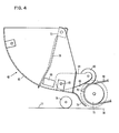
- FIGURE 4 shows the structure associated with the turnaround function applied to the sheet in the duplex return loop.
- Sheets carried by vacuum belt 48 pass pinch roller 60 and are driven onto turnaround tray 62.
- Pinch rollers 60 are attached by yoke 64 to pivot shaft 65 and the lower surface 66 provides a deflector function for the sheets as they enter tray 62.
- the sheets pass discharge corona 68 to remove static charge as they enter tray 62.
- control fingers 70 which are spring loaded at 72 to stop the sheet and hold it against the deflector roll or turnaround roll 75 so that the edge of the sheet is engaged by teeth such as 76 on roll 75.
- Tooth 76 is one of a plurality of teeth spaced around roll 75 which carry the sheet trailing edge into the aligner area 36 below roll 75. Thus, teeth 76 reverse the direction of the sheet and reintroduce it into the aligner 36.
- sheets extracted from supply source bin 34 are driven over paper path 77 and are engaged by drive roller 78 to introduce them into the aligner area 36.
- a sensor ⁇ (not shown) detects the movement of the sheet leading edge from tray 62 into the output guide 79 and informs the machine controls of the location of the paper.
- FIGURE 1 illustrates this dealignment arrangement.
- Sheet 80 is shown in the primary paper path against the aligner 36 reference edge 82. As the sheet progresses through the paper path, it eventually assumes an orientation as shown at 83 with a drift 84 which can occur during feed. If the sheet is reintroduced into aligner 36 with drift 84, the sheet may interfere with the leading edge of aligner reference edge 82 and jam.
- the duplex assembly is rotated in relation to the primary paper path to pull the edge away from the aligner 36 with this shown as the skew angle 86 associated with sheet 85.
- the sheet edge aligns itself with reference edge 82 as it reverses its movement into aligner 36.
- Fingers 87 and 88 engage the leading edge of the sheet 85 as it is introduced to tray 62 and are themselves skewed to ensure that the sheet from the vacuum transport 41 approaches aligner 36 on movement reversal in the correct position.
- the vacuum at plenum 50 is sufficient to hold the sheet firmly to vacuum belts 48 around guide 53 and until the sheet is firmly held by plenum 51. Since power from vacuum belts 48 drives the system, rolls 55 (FIGURES 2 and 3) and 75 (FIGURE 4) are preferably elastomer coated to increase friction against vacuum belts 48.
- Printer 10 is controlled as a high throughput printer and advantageously cooperates with the machine emitter to utilize every possible transfer cycle, as is illustrated in FIGURE 6.
- the duplex recirculating path is designed to accommodate a maximum of four sheets (sheets A-D in FIGURE 1) at any given time.
- sheets A-D in FIGURE 1 the sheets are picked in groups of four and exit from ' printer 10 in groups of four. Any sheet is selectable for the first duplex sheet depending on the duplex loop velocity.
- the transfer points without a sheet feed are the duplex transfers.
- the first duplex copy is limited to specific points such as the third, fifth or seventh transfer because of the pick cycle.
- the duplex loop velocity is very high or very low (a long path with a large buffer or a high-speed marginal reliability paper feed).
- at least two possible transfer cycles are lost, thus decreasing the throughput and the duplex selector vane must operate for every sheet.
- Using the timing shown in FIGURE 6 allows logic changes in machine operation with relative ease during the duplex mode. Some examples are changes in detach pressure, varied vacuum transport pressure and varied aligner plenum pressure. These are changeable for duplexed copies with the FIGURE 6 timing because of the grouped processing and allow accommodation of machine parameter control to maximize throughput.
- the FIGURE 6 chart illustrates continuous copy cycle operation where transfer cycles 1, 2, 3, and 4 are used to transfer images to the sheets as picked.
- transfer cycles 5, 6, 7, and 8 are used as the first duplex transfers depending on the paper velocity through the duplex loop.
- the duplex loop velocity is established for optimum feed reliability.
- the pulses represented as group 90 correspond to the sequential picking of four sheets of paper from supply source bin 34 in FIGURE 1.
- the transfer/fuse group 91 symbolically illustrates that the sheets sequentially receive the images associated with the second, fourth, sixth, and eighth page of the copy in process.
- the first, third, fifth, and seventh images are placed on the sheets in sequence as shown at group 92.
- the properly imaged set of sheets is shown as an. exiting group at 93 wherein the sheets will have the proper ordered sequence as they fall into output receptacle 35.
- the machine continues with the next group of four sheets beginning with sheet E (FIGURE 1) as shown in FIGURE 6.
- sheet E FIGURE 1
- the sheet velocity in a duplex loop to accomplish the timings is selected so that the first sheet is reintroduced to the paper aligner 36 as if it had originated from paper source drawer 34.
- the second side copying is underway, no sheets are picked from paper drawer 34.
- the system as shown and described avoids sheet turning in reversal at high velocity which requires relatively high cost and also acceptance of lower machine operation reliability. By the system as shown and described, paper path direction switching is minimized thus increasing machine reliability.
- duplex loop velocity is controlled and maintained at a reasonable level and the system has freedom to select which copy is the first duplex copy.
- the embodiment shown is controllable so that even a run of only a single duplex sheet is processed at a throughput comparable to prior art duplex machines.
Landscapes
- Physics & Mathematics (AREA)
- General Physics & Mathematics (AREA)
- Counters In Electrophotography And Two-Sided Copying (AREA)
- Conveyance By Endless Belt Conveyors (AREA)
- Control Or Security For Electrophotography (AREA)
- Separation, Sorting, Adjustment, Or Bending Of Sheets To Be Conveyed (AREA)
Applications Claiming Priority (2)
| Application Number | Priority Date | Filing Date | Title |
|---|---|---|---|
| US455368 | 1983-01-03 | ||
| US06/455,368 US4488801A (en) | 1983-01-03 | 1983-01-03 | Maximum throughput duplexing system for xerographic machines |
Publications (2)
| Publication Number | Publication Date |
|---|---|
| EP0114966A1 true EP0114966A1 (de) | 1984-08-08 |
| EP0114966B1 EP0114966B1 (de) | 1987-10-28 |
Family
ID=23808508
Family Applications (1)
| Application Number | Title | Priority Date | Filing Date |
|---|---|---|---|
| EP83111760A Expired EP0114966B1 (de) | 1983-01-03 | 1983-11-24 | Zweiseitenkopiersystem mit maximalem Durchsatz für xerographische Maschinen |
Country Status (4)
| Country | Link |
|---|---|
| US (1) | US4488801A (de) |
| EP (1) | EP0114966B1 (de) |
| JP (1) | JPS59124351A (de) |
| DE (1) | DE3374231D1 (de) |
Cited By (3)
| Publication number | Priority date | Publication date | Assignee | Title |
|---|---|---|---|---|
| GB2203381A (en) * | 1987-03-13 | 1988-10-19 | Ricoh Kk | Printer using a thermosensitive stencil for reproducing the same or different images of a plurality of documents side by side on a single sheet of greater size than the documents |
| GB2229137A (en) * | 1989-02-01 | 1990-09-19 | Ricoh Kk | Method of forming two-sided prints |
| EP0409627A3 (en) * | 1989-07-19 | 1991-05-15 | Xerox Corporation | Batch mode duplex printing |
Families Citing this family (11)
| Publication number | Priority date | Publication date | Assignee | Title |
|---|---|---|---|---|
| GB2187171B (en) * | 1986-01-10 | 1990-10-03 | Canon Kk | Recording apparatus |
| US4699367A (en) * | 1986-02-24 | 1987-10-13 | Eastman Kodak Company | Sheet turnover mechanism |
| US4943832A (en) * | 1988-06-09 | 1990-07-24 | Minolta Camera Kabushiki Kaisha | Image forming apparatus |
| US4928147A (en) * | 1989-02-27 | 1990-05-22 | International Business Machines Corporation | Printers with simplex and duplex cut sheet fusing |
| US4928127A (en) * | 1989-05-30 | 1990-05-22 | Xerox Corporation | Sheet circulation in a duplex printer |
| US4928128A (en) * | 1989-05-30 | 1990-05-22 | Xerox Corporation | Sheet circulation in a duplex printer |
| US5790677A (en) * | 1995-06-29 | 1998-08-04 | Microsoft Corporation | System and method for secure electronic commerce transactions |
| US5689565A (en) * | 1995-06-29 | 1997-11-18 | Microsoft Corporation | Cryptography system and method for providing cryptographic services for a computer application |
| NL1003679C2 (nl) * | 1996-07-25 | 1998-01-28 | Oce Tech Bv | Afdrukinrichting voor het afdrukken van tonerpoederbeelden op beide zijden van een beeldontvangstdrager. |
| US6167231A (en) * | 1999-03-31 | 2000-12-26 | Hewlett-Packard Company | Print recording apparatus having modular autoduplex mechanism |
| US7130574B2 (en) * | 2004-03-26 | 2006-10-31 | Lexmark International, Inc. | Image forming device with multimode duplexer |
Citations (5)
| Publication number | Priority date | Publication date | Assignee | Title |
|---|---|---|---|---|
| DE2534977A1 (de) * | 1974-08-05 | 1976-02-19 | Xerox Corp | Verfahren und system zum projizieren der beiden seiten eines originales auf eine bildebene |
| US4116558A (en) * | 1977-02-09 | 1978-09-26 | Xerox Corporation | Duplex system and method for pre-collation copiers |
| US4264183A (en) * | 1979-06-04 | 1981-04-28 | Eastman Kodak Company | Duplex copying apparatus and method |
| US4272181A (en) * | 1978-12-29 | 1981-06-09 | International Business Machines Corporation | Electrophotographic printer with duplex printed sheet output |
| US4335954A (en) * | 1981-03-04 | 1982-06-22 | Xerox Corporation | Copier registration method and apparatus |
Family Cites Families (8)
| Publication number | Priority date | Publication date | Assignee | Title |
|---|---|---|---|---|
| US4078787A (en) * | 1976-03-30 | 1978-03-14 | Eastman Kodak Company | Automatic transfer from collate to noncollate modes of recirculating feeder and copier operation |
| US4132398A (en) * | 1976-05-22 | 1979-01-02 | Hauni-Werke Korber & Co. Kg. | Apparatus for removing sheets from stacks |
| US4166614A (en) * | 1977-08-18 | 1979-09-04 | Xerox Corporation | Jogging and normal force for sheet feeding |
| IT1091500B (it) * | 1977-11-25 | 1985-07-06 | Olivetti Ing C E C Spa | Macchina copiatrice elettrofotografica con recto verso automatico di tipo perfezionato |
| US4234180A (en) * | 1979-06-27 | 1980-11-18 | Xerox Corporation | Recirculating document handler configuration |
| US4355880A (en) * | 1980-06-02 | 1982-10-26 | Xerox Corporation | Forward order document copying method |
| US4313673A (en) * | 1979-10-30 | 1982-02-02 | Xerox Corporation | Duplex operation in a reproduction machine |
| JPS5821267A (ja) * | 1981-07-30 | 1983-02-08 | Minolta Camera Co Ltd | 両面記録方式 |
-
1983
- 1983-01-03 US US06/455,368 patent/US4488801A/en not_active Expired - Lifetime
- 1983-10-19 JP JP58194488A patent/JPS59124351A/ja active Pending
- 1983-11-24 EP EP83111760A patent/EP0114966B1/de not_active Expired
- 1983-11-24 DE DE8383111760T patent/DE3374231D1/de not_active Expired
Patent Citations (5)
| Publication number | Priority date | Publication date | Assignee | Title |
|---|---|---|---|---|
| DE2534977A1 (de) * | 1974-08-05 | 1976-02-19 | Xerox Corp | Verfahren und system zum projizieren der beiden seiten eines originales auf eine bildebene |
| US4116558A (en) * | 1977-02-09 | 1978-09-26 | Xerox Corporation | Duplex system and method for pre-collation copiers |
| US4272181A (en) * | 1978-12-29 | 1981-06-09 | International Business Machines Corporation | Electrophotographic printer with duplex printed sheet output |
| US4264183A (en) * | 1979-06-04 | 1981-04-28 | Eastman Kodak Company | Duplex copying apparatus and method |
| US4335954A (en) * | 1981-03-04 | 1982-06-22 | Xerox Corporation | Copier registration method and apparatus |
Non-Patent Citations (1)
| Title |
|---|
| Patent Abstracts of Japan vol. 4, no. 43 page 126P5 & JP-A-55-15191 * |
Cited By (6)
| Publication number | Priority date | Publication date | Assignee | Title |
|---|---|---|---|---|
| GB2203381A (en) * | 1987-03-13 | 1988-10-19 | Ricoh Kk | Printer using a thermosensitive stencil for reproducing the same or different images of a plurality of documents side by side on a single sheet of greater size than the documents |
| GB2203381B (en) * | 1987-03-13 | 1991-07-03 | Ricoh Kk | Printer using a mimeograph |
| GB2229137A (en) * | 1989-02-01 | 1990-09-19 | Ricoh Kk | Method of forming two-sided prints |
| US5132720A (en) * | 1989-02-01 | 1992-07-21 | Ricoh Company, Ltd. | Method of forming two-sided prints |
| GB2229137B (en) * | 1989-02-01 | 1993-03-24 | Ricoh Kk | Method of forming two-sided prints |
| EP0409627A3 (en) * | 1989-07-19 | 1991-05-15 | Xerox Corporation | Batch mode duplex printing |
Also Published As
| Publication number | Publication date |
|---|---|
| JPS59124351A (ja) | 1984-07-18 |
| DE3374231D1 (en) | 1987-12-03 |
| US4488801A (en) | 1984-12-18 |
| EP0114966B1 (de) | 1987-10-28 |
Similar Documents
| Publication | Publication Date | Title |
|---|---|---|
| US5008713A (en) | Sheet conveying apparatus and sheet conveying method | |
| EP0114966B1 (de) | Zweiseitenkopiersystem mit maximalem Durchsatz für xerographische Maschinen | |
| EP0659668A2 (de) | Ein Abbildungsgerät besitzt einen zweiten Weg mit einer Wendevorrichtung | |
| US6619657B2 (en) | Curl correction device, and image forming apparatus having the curl correction device | |
| JP2003207954A (ja) | 両面プリントシート装置の一定反転速度タイミング方法 | |
| GB2228727A (en) | Paper conveying apparatus | |
| US6626428B2 (en) | Sheet ejection mechanism | |
| JPH0521229B2 (de) | ||
| US6778787B2 (en) | Image forming apparatus with control to divert sheet to usable path | |
| EP0713156B1 (de) | Blattransportvorrichtung für einen Drucker zum beidseitigen Drucken | |
| US4978111A (en) | Recording sheet stacking apparatus in image recording system | |
| GB2060577A (en) | Registering sheets | |
| US4170349A (en) | Self-contained motor-driven collator deflector | |
| US5048817A (en) | Dynamic edge guide for side registration systems | |
| US5012296A (en) | Method of and copying machine for copying originals in order on both sides of receiving sheets | |
| US4920383A (en) | Paper handling for repetitive movement of variable length media through an image transfer station | |
| CN101927915A (zh) | 输送装置及具有该输送装置的图像形成装置 | |
| US8055182B2 (en) | Image forming apparatus | |
| US5584474A (en) | Single sheet feed device for an electrophotographic printer or copier | |
| US11360421B2 (en) | Sheet sorting device, post-processing apparatus, and image forming system | |
| US5293204A (en) | Copier with a superposed-sheet separation mechanism | |
| JP4027046B2 (ja) | 画像形成装置 | |
| EP2225615B1 (de) | Verfahren zum drucken eines bildes auf ein blatt in einem drucker | |
| JP2692868B2 (ja) | シート搬送装置 | |
| CA2053555C (en) | Copier with a superposed-sheet separation mechanism |
Legal Events
| Date | Code | Title | Description |
|---|---|---|---|
| PUAI | Public reference made under article 153(3) epc to a published international application that has entered the european phase |
Free format text: ORIGINAL CODE: 0009012 |
|
| AK | Designated contracting states |
Designated state(s): DE FR GB IT |
|
| 17P | Request for examination filed |
Effective date: 19841123 |
|
| 17Q | First examination report despatched |
Effective date: 19860610 |
|
| GRAA | (expected) grant |
Free format text: ORIGINAL CODE: 0009210 |
|
| AK | Designated contracting states |
Kind code of ref document: B1 Designated state(s): DE FR GB IT |
|
| PG25 | Lapsed in a contracting state [announced via postgrant information from national office to epo] |
Ref country code: IT Free format text: LAPSE BECAUSE OF FAILURE TO SUBMIT A TRANSLATION OF THE DESCRIPTION OR TO PAY THE FEE WITHIN THE PRESCRIBED TIME-LIMIT;WARNING: LAPSES OF ITALIAN PATENTS WITH EFFECTIVE DATE BEFORE 2007 MAY HAVE OCCURRED AT ANY TIME BEFORE 2007. THE CORRECT EFFECTIVE DATE MAY BE DIFFERENT FROM THE ONE RECORDED. Effective date: 19871028 |
|
| REF | Corresponds to: |
Ref document number: 3374231 Country of ref document: DE Date of ref document: 19871203 |
|
| ET | Fr: translation filed | ||
| PLBI | Opposition filed |
Free format text: ORIGINAL CODE: 0009260 |
|
| 26 | Opposition filed |
Opponent name: OCE-NEDERLAND B.V., VENLO Effective date: 19880627 |
|
| RDAG | Patent revoked |
Free format text: ORIGINAL CODE: 0009271 |
|
| STAA | Information on the status of an ep patent application or granted ep patent |
Free format text: STATUS: PATENT REVOKED |
|
| 27W | Patent revoked |
Effective date: 19890424 |
|
| GBPR | Gb: patent revoked under art. 102 of the ep convention designating the uk as contracting state | ||
| PGFP | Annual fee paid to national office [announced via postgrant information from national office to epo] |
Ref country code: FR Payment date: 19891025 Year of fee payment: 7 |