EP0114977A1 - Cabine thermique solaire pour le traitement de personnes et/ou d'animaux par le rayonnement solaire, en particulier pour des bains sauna - Google Patents
Cabine thermique solaire pour le traitement de personnes et/ou d'animaux par le rayonnement solaire, en particulier pour des bains sauna Download PDFInfo
- Publication number
- EP0114977A1 EP0114977A1 EP83111995A EP83111995A EP0114977A1 EP 0114977 A1 EP0114977 A1 EP 0114977A1 EP 83111995 A EP83111995 A EP 83111995A EP 83111995 A EP83111995 A EP 83111995A EP 0114977 A1 EP0114977 A1 EP 0114977A1
- Authority
- EP
- European Patent Office
- Prior art keywords
- cabin
- solar
- treatment
- der
- window
- Prior art date
- Legal status (The legal status is an assumption and is not a legal conclusion. Google has not performed a legal analysis and makes no representation as to the accuracy of the status listed.)
- Granted
Links
- 238000011282 treatment Methods 0.000 title claims description 29
- 241001465754 Metazoa Species 0.000 title claims description 5
- 230000005855 radiation Effects 0.000 title description 4
- 238000007789 sealing Methods 0.000 claims description 16
- 239000011521 glass Substances 0.000 claims description 13
- XLYOFNOQVPJJNP-UHFFFAOYSA-N water Substances O XLYOFNOQVPJJNP-UHFFFAOYSA-N 0.000 claims description 6
- 239000003570 air Substances 0.000 claims description 5
- 239000000428 dust Substances 0.000 claims description 5
- 230000000694 effects Effects 0.000 claims description 4
- 230000002093 peripheral effect Effects 0.000 claims 1
- 230000008878 coupling Effects 0.000 abstract 1
- 238000010168 coupling process Methods 0.000 abstract 1
- 238000005859 coupling reaction Methods 0.000 abstract 1
- 239000002184 metal Substances 0.000 description 4
- 230000002787 reinforcement Effects 0.000 description 3
- 238000009423 ventilation Methods 0.000 description 3
- 230000008901 benefit Effects 0.000 description 2
- 239000013013 elastic material Substances 0.000 description 2
- 230000035876 healing Effects 0.000 description 2
- 208000012641 Pigmentation disease Diseases 0.000 description 1
- 238000004378 air conditioning Methods 0.000 description 1
- 230000009286 beneficial effect Effects 0.000 description 1
- 238000009395 breeding Methods 0.000 description 1
- 230000001488 breeding effect Effects 0.000 description 1
- 238000010276 construction Methods 0.000 description 1
- 230000029142 excretion Effects 0.000 description 1
- 239000004744 fabric Substances 0.000 description 1
- 230000005484 gravity Effects 0.000 description 1
- 239000000463 material Substances 0.000 description 1
- 230000004048 modification Effects 0.000 description 1
- 238000012986 modification Methods 0.000 description 1
- 230000000149 penetrating effect Effects 0.000 description 1
- 239000012858 resilient material Substances 0.000 description 1
- 239000007787 solid Substances 0.000 description 1
- 239000000725 suspension Substances 0.000 description 1
- 210000004243 sweat Anatomy 0.000 description 1
- 210000000106 sweat gland Anatomy 0.000 description 1
Images


Classifications
-
- A—HUMAN NECESSITIES
- A61—MEDICAL OR VETERINARY SCIENCE; HYGIENE
- A61N—ELECTROTHERAPY; MAGNETOTHERAPY; RADIATION THERAPY; ULTRASOUND THERAPY
- A61N5/00—Radiation therapy
- A61N5/06—Radiation therapy using light
Definitions
- the invention relates to a thermal-solar treatment cabin for people and / or animals for treatment by the Wikrung solar radiation, especially for solar sauna baths.
- the invention has for its object to provide a cabin of the type mentioned, the effective treatment of people and / or animals by direct and / or indirect action of the sun's rays especially for healing purposes, such as for heliotherapeutic treatment, but also for general purposes Hydiene and body care as well as to improve and rationalize the breeding of pets and / or animals living in captivity.
- the treatment cabin should enable a rational use of the effect of the light rays (in particular the ultraviolet and infrared rays) and / or the thermal energy of the sun rays under controllable conditions and with high efficiency, and in particular in that Treating subject promote both skin pigmentation and sweat excretion through the sweat glands;
- the treatment booth according to the invention should be easy to move and / or orientate so that its location and / or position in relation to the solar radiation can be changed as required.
- the treatment booth according to the invention should be simple in its construction and operation, and reliable and safe in its use.
- the treatment booth according to the invention is characterized (claim 1) by at least one glass window which is inclined at the top towards the interior of the booth in such a way that the sun's rays fall appropriately into the interior of the booth and so benefit the subject to be treated Can fully develop effects.
- the Gals window which is inclined inwards at the top, is optionally adjustable in the angle of inclination and has means for fixing the window in the set inclination (claim 2).
- sealing means are provided between the glass window, the door and the associated wall parts of the treatment cabin in order to prevent air, water, dust and the like from penetrating due to weather conditions. to prevent (claim 3).
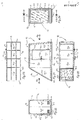
- 1 to 5 and 9 to 20 show a simplified first embodiment of the thermal-solar treatment cabin according to the invention, which is designated in its entirety by 10.
- the cabin 10 comprises a rectangular base plate 11, vertically arranged, lateral longitudinal walls 12, 13 with a trapezoidal, but differently inclined, upwardly converging sides, and a rectangular transverse wall 14 for connecting the less inclined side of each longitudinal wall 12, 13 and the bottom plate 11.
- a rigid, rectangular flat roof 15 is connected to the upper sides of the longitudinal walls 12, 13 and the transverse wall 14, while the remaining opening, which by the free transverse side of the bottom plate 11 and the roof 15 and the more inclined sides of the Longitudinal walls 12, 13 by a correspondingly dimensioned fixed window 16 is closed with a rectangular window frame 16.1, this window above, ie; the inclination of the mentioned sides of the longitudinal walls is accordingly inclined towards the interior of the cabin 10 (Fig. 1 to 5).
- This support structure consisting of vertical supports 10.1 and cross members 10.2 and spars 10.3 cooperates with a corresponding support and reinforcement frame for base plate 11 consisting of cross members 11.1 and spars 11.2 (FIGS. 3 and 9).
- the frame 16.1 of the glass window 16 is articulated according to a modified embodiment with its lowermost cross member 16.3 by means of a hinge 17 with hinge bolts 17.1 directed transversely to the base plate according to a horizontal axis YY to the base plate.
- the window frame 16.1 can be pivoted about the aforementioned axis YY in a vertical longitudinal plane of the cabin 10.
- the window frame 16.1 has locking bolts 16.5 at the ends of its uppermost traverse 16.4, the slides 16.6 of which can be displaced in their guides according to a horizontal axis ZZ parallel to the axis YY of the hinge bolts 17.1 (FIG. 10).
- This locking slide 16.6 engage in their advanced position from the guides in two corresponding axially opposite and symmetrically arranged with respect to the vertical longitudinal center ne ne blind holes, for example 12.1 (Fig. 11), which arc inside the longitudinal walls 12, 13 in a circle with the center point on the mentioned axis YY and with a radius corresponding to the distance between this axis YY and the axis ZZ of the locking slide 16.6 (only the arrangement is in the figures tion of the blind holes 12.1 visible in one longitudinal wall 12).
- the window frame 16.1 with the glass window 16 can be pivoted into several positions with different angles of inclination and can be determined by means of the bolt 16.5 or the bolt slide 16.6 under their engagement in the corresponding blind holes, for example 12.1 of the longitudinal walls of the cabin 10 in the selected pivot position.
- the glass window 16 is shown with fully drawn lines in its swivel position which is minimally inclined with respect to the vertical and with dashed lines in its maximally inclined snowing position.
- a rectangular through opening 12.2 (Fig. 1, 9, 10) is provided, which can be closed by means of a correspondingly dimensioned outer door leaf 12.3 with a locking handle 12.4.
- This door leaf can be pivoted in the open or closed position by means of hinges 12.5 with vertically directed hinge bolts, the hinge leaves of which are fastened on the outside to the longitudinal wall 12 and on the door leaf 12.3 (FIGS. 1, 17, 18).
- sealing means 12.6 In order to achieve a safe seal against the ingress of air, dust, water and other weather influences when the door is closed, sealing means 12.6 with a tubular profile 12.7, which slightly protrudes when the door 12.3 is open, are made between the door leaf 12.3 and the wall opening 12.2 along the circumference resilient material attached to the outside of the opening 12.2 (Fig. 17).
- the tubular profile 12.7 of this sealing means 12.6 is elastically deformed when the door leaf 12.3 is closed and brings about the desired sealing under tight contact with the inside of the door leaf circumference (FIG. 18).
- the tubular sealing means 12.6 consist of a simple one Strips of elastic material, for example a rubber band, which is bent in length approximately in the manner of a tubular hose and is fastened with its inwardly directed longitudinal edges by means of screws to the circumference of the wall opening 12.2 of the cabin 10.
- sealing means 16.7 with tubular profile 16.8 in a design similar to the mentioned sealing means 12.6 by means of continuous screws with washer on the inside along the side rails 16.9, 16.10 of the pivotable window frame 16.1 with tight contact of the tubular profile 16.8 against them Inside of the longitudinal walls 12, 13 of the Kabi ne 10 attached.
- a strip 16.11 of rubber-elastic material along the entire cross member 16.3 is between the hinge leaves 17 and the inside of the base plate 11 and the bottom cross member 16.3 of the swivel frame 16.1 attached in the manner of an elongated flexible hinge for connecting the swivel frame 16.1 to the base plate 11.
- This elastic strip 16.11 is also fastened, for example by means of screws, to the cross member 16.3 of the swivel frame 16.1 and the base part 11 in the space between the hinges 17 (FIG. 10) in order to achieve a snug fit against these parts along its entire length.
- the elastic strip 16.11 therefore forms an effective seal between the articulation parts in cooperation with the hinges 17 during the pivoting movement of the window frame 16.1.
- strip-shaped sealing means 16.12 of flexible, impermeable dimensions between the uppermost cross member 16.4 of the swivel frame 16.1 and the flat roof 15 used material.
- This sealing strip 16.12 has a width which is approximately the distance between the free transverse side of the roof 15 and the vertical transverse plane, which in the interior of the cabin 10 limits the position of the window frame 16.1 pivoted in by the greatest angle of inclination (shown by broken lines in FIG. 11) Position).
- the strip 16.12 is attached, for example, by means of screws with one of its longitudinal edges to the underside of the roof 15 of the entire transverse width.
- This strip is set back from the free crossmember of the roof 15 by a smaller distance than the width of the strip 16.12, while on the other longitudinal edge of the strip 16.12 is fixed, for example by means of screws, to the top of the uppermost traverses 16.4 of the pivoting frame 16.1. Due to this arrangement, the sealing strip 16.12 accompanies the frame 16.1 in its pivoting movement without hindering this pivoting movement about the axis YY, and thereby provides a secure seal against the ingress of dust, air, water and weather influences between the top crossmember 16.4 of the frame 16.1 and the roof 15. Instead of such a rubber-elastic strip can of course also a sufficiently strong, against air, water and the like. impermeable fabric seal can be used.
- ventilation hoods 14.1 are provided in the transverse wall. These ventilation hoods 14.1 (FIGS. 9, 15, 16) each consist of a slot-like opening 14.2, which is protected by a corresponding grille 14.3 and whose opening width can be adjusted by hand by suitable means 14.4 to regulate the air flow.
- These means 14.4 comprise a cover 14.5 which can be displaced on the transverse wall 14 in horizontal guides 14.6 (FIGS. 15, 16). 16, these means 14.4 are shown with solid lines in the closed state, in which the cover 14.5 is completely pushed into its guides 14.6, so that the opening 14.2 is closed by the cover and each air passage is prevented; The dashed lines, on the other hand, indicate the cover 14.5 in its maximum extended position from the guides 14.6, in which the means 14.4 are completely open and the air flow through the opening 14.2 is fully released.
- the treatment cabin 10 is with a known, not shown interior lighting, which is powered by a battery with electrical power, see ver.
- the cabin 10 can be divided into a plurality of interiors, e.g. also to separate a changing room.
- FIG. 6 to 8 show a second embodiment of the thermal-solar treatment cabin according to the invention, in which, for easier transportation and orientation with respect to the incident sun rays S, the cabin 10, in the manner of a trailer vehicle, has a driving axle 20 with tires 21 and a front, horizontally oriented rigid Has frame 30.
- This frame is firmly connected to the base part 11 and is designed as a drawbar for connection to a (not shown) towing vehicle.
- this cabin has 10 foldable trestles 40 which support the cabin after the cabin has been removed from the towing vehicle.
- the driving Axis 20 is connected in a known manner to the base part 11 in a position set back relative to the center of gravity of the load with the interposition of spring suspensions, for example leaf springs 22.
- the frosted wheels 21 are partially protected by fenders 23, which are fastened to the bottom part 11.
- the front rigid frame 30 has, in the manner of conventional drawbars for trailers, at least one crossbeam (not shown) which is fastened to the underside of the base plate 11, and two spars 31 which are firmly connected to this crossbeam and diverge in the form of a fork from the drawbar with the cabin 10 connect.
- This cross member and the spars 31 of the frame 30 are formed by solid metal profiles, for example square profiles.
- the bars 31 of the frame 30 are provided at the free end with a pull hook 32 for connection to the towing vehicle.
- the front frame 30 can be articulated on the base part 11 and pivoted in a vertical longitudinal plane of the cabin 10.
- the foldable support brackets 40 are formed by two swivel arms 41 with feet 42 and are hinged at their upper end to support forks 43 which are symmetrically spaced from the center line of the cables and near the front end of the base part 11.
- the articulation of the swivel arms 41 in the support forks 43 is carried out by means of horizontally and transversely to the cabin 10 such angeord Neten bolts 44 that the arms 41 are pivotable in the vertical longitudinal planes of the cabin 10.
- Each swivel arm consists of two telescopically displaceable tube pieces, each with a plurality of radially and coaxially arranged holes for pushing through a locking pin in order to set a more or less large length of the telescopically displaceable tube pieces of each swivel arm 41.
- the swivel arms 41 folded in the position of use can be adjusted in length depending on the nature of the base. Except for use, the swivel arms 41 are in a position tilted against the underside of the bottom plate 11 by means of their locking pins mentioned, which also engage in holes 43.1 provided in the support 43 (FIG. 6) with axes parallel to the pivot bolts 44, can be fixed.
- the structure of the cabin 10 according to this embodiment is entirely the same as that described and illustrated with reference to the first embodiment.
- 21 to 37 show a third embodiment of the thermal-solar treatment cabin according to the inven tion, wherein the cabin 10 consists of parts that can be dismantled and reassembled in a simple manner.
- the Bodenplat te 11 the two longitudinal walls 12, 13, the transverse wall 14 and the roof 15 are formed by attachable rectangular plate parts 11P, 12P, 13P, 14P and 15P; for the longitudinal walls 12, 13 a triangular plate part 12P1, 13P1 are also provided at one end and a trapezoidal part 12P2, 13P2 at the other end.
- These plate parts are assembled either by butt connection by means of brackets 50 and screws 51 (Fig. 36), or by a form fit by means of overlap and screws 52 (Fig. 35), or by a form fit by means of mortise and tenon (Fig. 37), whereby a connection has the advantage of a better seal through positive locking. Accordingly, according to FIGS.
- the support structure for the cabin 10 consisting of supports 10.1, crossbeams 10.2 and spars 10.3 and the Ver consisting of crossbeams 11.1 and spars 11.2 stiffening frame for the base plate 11 assembled by detachable connection of metal profiles with each other and with the individual plate parts using screws with or without nuts (Fig. 31 to 34).
- an additional frame consisting of supports 10.5 and crossbeams 10.6 is provided for the transverse wall 14 for stronger reinforcement of the supporting frame.
- This additional frame is detachably connected to the Hol men 10.3 and the spars 10.4, which serve for further connec tion of the longitudinal walls 12, 13 with the base plate 11 and also consists of metal profiles that are detachably joined together and with the above-mentioned structural parts.
- a frame 16i made of metal profiles also reinforces the swivel frame 16.1 of the glass window 16 (FIG. 29).
- the individual components of the cabin 10 according to this embodiment are sufficiently clear from the figures, so that a further description of the same is unnecessary.
- FIGS. 38 to 41 A fourth embodiment of the treatment booth according to the invention is shown in FIGS. 38 to 41 and designated 60 in its entirety.
- the cabin 60 is designed in the manner of a straight circular cylinder which is cut through an inclined plane (sectional area DD in FIG. 38). This cut surface is based on a diameter of the upper base surface and extends to just above the lower base surface of the cylinder (FIGS. 38 and 41). The intersection of this sectional plane with the outer surface of the cylinder is an approximately semi-elliptical profile (Fig. 40).
- the cabin 60 has a circular base plate 61 and a vertical jacket wall 62 with a window opening 63 which extends essentially over the entire height of the cabin and, as mentioned, has an approximately semi-elliptical shape.
- a rigid, semicircular flat roof 64 is firmly connected to the jacket wall and to the diameter side 64.1 which delimits the above-mentioned window opening 63 in the jacket wall 62 at the top (FIG. 41).
- the window opening formed between the jacket wall 62 and the roof 64 is encompassed along its circumference by a continuous frame 65.1 which projects into the opening in the manner of a flange and to which a correspondingly shaped window glazing 65.2 is fastened.
- this embodiment also has a correspondingly large window 65 which is inclined inwards at the top.
- this window 65 can also have a swivel frame which is articulated on the diameter side 64.1 of the roof 64 and is provided along its circumference with suitable sealing means.
- the cabin has a pivoting window equipped with lens glazing so that the incident sun rays can be appropriately focused by changing the angle of inclination of the window and the effects of the sun radiation can thereby be controlled in a manner appropriate to the treatment.
- the sealing means 16.7 provide a tight seal against air, dust, water and the like. between the side rails 16.9, 16.10 of the swivel frame 16.1 for the glass window 16 and the side walls 12, 13 of the cabin 10 and this also during the swivel movement of the frame 16.1 about the axis Y-Y by the sliding contact ih-. res tubular sealing body 16.8 against the inner surface of the adjacent side wall despite the high elastic deformability of this tubular sealing body.
Landscapes
- Health & Medical Sciences (AREA)
- Engineering & Computer Science (AREA)
- Biomedical Technology (AREA)
- Pathology (AREA)
- Nuclear Medicine, Radiotherapy & Molecular Imaging (AREA)
- Radiology & Medical Imaging (AREA)
- Life Sciences & Earth Sciences (AREA)
- Animal Behavior & Ethology (AREA)
- General Health & Medical Sciences (AREA)
- Public Health (AREA)
- Veterinary Medicine (AREA)
- Body Structure For Vehicles (AREA)
- Devices For Medical Bathing And Washing (AREA)
- Radiation-Therapy Devices (AREA)
Priority Applications (1)
| Application Number | Priority Date | Filing Date | Title |
|---|---|---|---|
| AT83111995T ATE35224T1 (de) | 1982-12-24 | 1983-11-30 | Thermisch-solare behandlungscabine fuer personen und/oder tiere zur behandlung durch die wirkung der sonnenstrahlung, insbesondere fuer solare sauna-baeder. |
Applications Claiming Priority (2)
| Application Number | Priority Date | Filing Date | Title |
|---|---|---|---|
| IT6852182 | 1982-12-24 | ||
| IT8268521A IT1212672B (it) | 1982-12-24 | 1982-12-24 | Abitacolo termico solare per il trattamento di persone e o animali agli effetti dei raggi solari in particolare per la sauna solare |
Publications (2)
| Publication Number | Publication Date |
|---|---|
| EP0114977A1 true EP0114977A1 (fr) | 1984-08-08 |
| EP0114977B1 EP0114977B1 (fr) | 1988-06-22 |
Family
ID=11309696
Family Applications (1)
| Application Number | Title | Priority Date | Filing Date |
|---|---|---|---|
| EP83111995A Expired EP0114977B1 (fr) | 1982-12-24 | 1983-11-30 | Cabine thermique solaire pour le traitement de personnes et/ou d'animaux par le rayonnement solaire, en particulier pour des bains sauna |
Country Status (4)
| Country | Link |
|---|---|
| EP (1) | EP0114977B1 (fr) |
| AT (1) | ATE35224T1 (fr) |
| DE (1) | DE3377110D1 (fr) |
| IT (1) | IT1212672B (fr) |
Cited By (6)
| Publication number | Priority date | Publication date | Assignee | Title |
|---|---|---|---|---|
| DE3919197A1 (de) * | 1989-05-12 | 1991-01-31 | Hoelter Heinz | Koerpererwaermungszelle mit uv-strahlenanordnung, luft- und luftimpulsmassage sowie entkeimter luftbefeuchtung |
| GB2316867A (en) * | 1996-09-07 | 1998-03-11 | Graham Davies | Mobile sauna |
| FR2785792A1 (fr) * | 1998-11-17 | 2000-05-19 | Cavel Laurent De | Sauna solaire |
| EP1870132A1 (fr) * | 2006-06-24 | 2007-12-26 | Albin Gödl | Dispositif pour éclairer un corps humain avec lumière solaire naturelle |
| DE202015007591U1 (de) | 2015-03-31 | 2016-01-14 | Manfred Jörg | Freiluft-Solarsauna |
| DE202018005659U1 (de) | 2018-04-16 | 2019-02-06 | Universität Stuttgart Körperschaft des öffentlichen Rechts | Windenergieanlage mit thermo-mechanischem Energiespeicher- und Energiewandlersystem zum klimaneutralen, umweltfreundlichen und energieautarken Betrieb einer Saunaanlage |
Families Citing this family (1)
| Publication number | Priority date | Publication date | Assignee | Title |
|---|---|---|---|---|
| DE102007027402A1 (de) | 2007-06-11 | 2008-12-18 | Bernhard Abmayr | Sonnenlichtkammer, insbesondere Sonnenlichtsauna oder Gewächshaus, sowie Konzentrieranordnung zum Konzentrieren von Licht |
Citations (6)
| Publication number | Priority date | Publication date | Assignee | Title |
|---|---|---|---|---|
| US1772219A (en) * | 1928-10-23 | 1930-08-05 | Kempton Edwin | Solar bath |
| US2493328A (en) * | 1946-07-23 | 1950-01-03 | Wandyak Anthony | Portable solarium |
| US2653612A (en) * | 1952-01-09 | 1953-09-29 | Charles R Hooe | Sunray heat cabinet |
| DE2624632A1 (de) * | 1976-06-02 | 1977-12-08 | Hartmut Gattinger Fa | Transportable, zerlegbare raumzelle |
| DE2943842A1 (de) * | 1979-10-30 | 1981-05-14 | Karl 7505 Ettlingen Freyt | Vorrichtung zum schattenbaden |
| US4277855A (en) * | 1980-01-25 | 1981-07-14 | Glen Poss | Portable sauna |
-
1982
- 1982-12-24 IT IT8268521A patent/IT1212672B/it active
-
1983
- 1983-11-30 AT AT83111995T patent/ATE35224T1/de not_active IP Right Cessation
- 1983-11-30 DE DE8383111995T patent/DE3377110D1/de not_active Expired
- 1983-11-30 EP EP83111995A patent/EP0114977B1/fr not_active Expired
Patent Citations (6)
| Publication number | Priority date | Publication date | Assignee | Title |
|---|---|---|---|---|
| US1772219A (en) * | 1928-10-23 | 1930-08-05 | Kempton Edwin | Solar bath |
| US2493328A (en) * | 1946-07-23 | 1950-01-03 | Wandyak Anthony | Portable solarium |
| US2653612A (en) * | 1952-01-09 | 1953-09-29 | Charles R Hooe | Sunray heat cabinet |
| DE2624632A1 (de) * | 1976-06-02 | 1977-12-08 | Hartmut Gattinger Fa | Transportable, zerlegbare raumzelle |
| DE2943842A1 (de) * | 1979-10-30 | 1981-05-14 | Karl 7505 Ettlingen Freyt | Vorrichtung zum schattenbaden |
| US4277855A (en) * | 1980-01-25 | 1981-07-14 | Glen Poss | Portable sauna |
Cited By (6)
| Publication number | Priority date | Publication date | Assignee | Title |
|---|---|---|---|---|
| DE3919197A1 (de) * | 1989-05-12 | 1991-01-31 | Hoelter Heinz | Koerpererwaermungszelle mit uv-strahlenanordnung, luft- und luftimpulsmassage sowie entkeimter luftbefeuchtung |
| GB2316867A (en) * | 1996-09-07 | 1998-03-11 | Graham Davies | Mobile sauna |
| FR2785792A1 (fr) * | 1998-11-17 | 2000-05-19 | Cavel Laurent De | Sauna solaire |
| EP1870132A1 (fr) * | 2006-06-24 | 2007-12-26 | Albin Gödl | Dispositif pour éclairer un corps humain avec lumière solaire naturelle |
| DE202015007591U1 (de) | 2015-03-31 | 2016-01-14 | Manfred Jörg | Freiluft-Solarsauna |
| DE202018005659U1 (de) | 2018-04-16 | 2019-02-06 | Universität Stuttgart Körperschaft des öffentlichen Rechts | Windenergieanlage mit thermo-mechanischem Energiespeicher- und Energiewandlersystem zum klimaneutralen, umweltfreundlichen und energieautarken Betrieb einer Saunaanlage |
Also Published As
| Publication number | Publication date |
|---|---|
| DE3377110D1 (en) | 1988-07-28 |
| IT1212672B (it) | 1989-11-30 |
| EP0114977B1 (fr) | 1988-06-22 |
| ATE35224T1 (de) | 1988-07-15 |
| IT8268521A0 (it) | 1982-12-24 |
Similar Documents
| Publication | Publication Date | Title |
|---|---|---|
| DE69114045T2 (de) | Heuwerbungsmachine mit mehreren Kreiseln. | |
| EP1884438B1 (fr) | Chariot pour pièces de petite taille | |
| EP0114977B1 (fr) | Cabine thermique solaire pour le traitement de personnes et/ou d'animaux par le rayonnement solaire, en particulier pour des bains sauna | |
| DE10066348B4 (de) | Vorrichtung zur Erhöhung des Fassungsvermögens eines nach oben offenen Korntanks eines Mähdreschers und Korntank sowie Mähdrescher mit einer derartigen Vorrichtung | |
| DE202007010786U1 (de) | Nutzfahrzeugaufbau mit Dach | |
| DE3907016A1 (de) | Fahrzeuganhaenger, insbesondere fuer den transport von pferden | |
| DE102011054205A1 (de) | Zelt | |
| DE19922512C1 (de) | Rückwand für ein Lastfahrzeug | |
| EP1690810A2 (fr) | Conteneur repliable et dispositif de vidage | |
| DE3437848C2 (fr) | ||
| DE3784214T2 (de) | Ladeflaechenrunge mit einer planenstuetze. | |
| DE3512271A1 (de) | Sonnen- und schutzueberdeckung fuer kraftfahrzeuge - inbesondere wohnmobile - und wohnanhaenger | |
| CH670200A5 (fr) | ||
| DE4235287A1 (de) | Transportables, begehbares Gehäuse | |
| EP4256954B1 (fr) | Enclos pour animaux d'élevage | |
| DE3306966C2 (de) | Schirm | |
| DE1455862A1 (de) | Zusammenlegbarer Wohnwagen | |
| DE3804707C2 (de) | Faltbarer Planenaufbau für Nutzfahrzeuge | |
| DE2840613A1 (de) | Wohneinrichtung fuer kleinwagen | |
| DE10343915B4 (de) | Kastenaufbau | |
| DE20212906U1 (de) | Landwirtschaftliche Hütte für Tiere, insbesondere Kälber | |
| WO2023156115A1 (fr) | Stalle transportable | |
| DE19839780A1 (de) | Spriegelausbildung für ein Planendach für Fahrzeugaufbauten und Container | |
| DE8509975U1 (de) | Sonnen- und Schutzüberdeckung für Kraftfahrzeuge- insbesondere Wohnmobile - und Wohnanhänger | |
| DE29702052U1 (de) | Vorrichtung zum auswechselbaren Halten eines Dach-, Seiten- und/oder Heckelementes an Kraftfahrzeugen |
Legal Events
| Date | Code | Title | Description |
|---|---|---|---|
| PUAI | Public reference made under article 153(3) epc to a published international application that has entered the european phase |
Free format text: ORIGINAL CODE: 0009012 |
|
| AK | Designated contracting states |
Designated state(s): AT BE CH DE FR GB LI LU NL SE |
|
| 17P | Request for examination filed |
Effective date: 19841222 |
|
| 17Q | First examination report despatched |
Effective date: 19860220 |
|
| GRAA | (expected) grant |
Free format text: ORIGINAL CODE: 0009210 |
|
| AK | Designated contracting states |
Kind code of ref document: B1 Designated state(s): AT BE CH DE FR GB LI LU NL SE |
|
| PG25 | Lapsed in a contracting state [announced via postgrant information from national office to epo] |
Ref country code: NL Effective date: 19880622 Ref country code: GB Free format text: LAPSE BECAUSE OF NON-PAYMENT OF DUE FEES Effective date: 19880622 |
|
| REF | Corresponds to: |
Ref document number: 35224 Country of ref document: AT Date of ref document: 19880715 Kind code of ref document: T |
|
| PG25 | Lapsed in a contracting state [announced via postgrant information from national office to epo] |
Ref country code: SE Effective date: 19880630 |
|
| REF | Corresponds to: |
Ref document number: 3377110 Country of ref document: DE Date of ref document: 19880728 |
|
| ET | Fr: translation filed | ||
| NLV1 | Nl: lapsed or annulled due to failure to fulfill the requirements of art. 29p and 29m of the patents act | ||
| PG25 | Lapsed in a contracting state [announced via postgrant information from national office to epo] |
Ref country code: LU Free format text: LAPSE BECAUSE OF NON-PAYMENT OF DUE FEES Effective date: 19881130 |
|
| GBV | Gb: ep patent (uk) treated as always having been void in accordance with gb section 77(7)/1977 [no translation filed] | ||
| PLBE | No opposition filed within time limit |
Free format text: ORIGINAL CODE: 0009261 |
|
| STAA | Information on the status of an ep patent application or granted ep patent |
Free format text: STATUS: NO OPPOSITION FILED WITHIN TIME LIMIT |
|
| 26N | No opposition filed | ||
| PGFP | Annual fee paid to national office [announced via postgrant information from national office to epo] |
Ref country code: DE Payment date: 19951123 Year of fee payment: 13 |
|
| PGFP | Annual fee paid to national office [announced via postgrant information from national office to epo] |
Ref country code: CH Payment date: 19961211 Year of fee payment: 14 |
|
| PGFP | Annual fee paid to national office [announced via postgrant information from national office to epo] |
Ref country code: BE Payment date: 19970109 Year of fee payment: 14 |
|
| PGFP | Annual fee paid to national office [announced via postgrant information from national office to epo] |
Ref country code: AT Payment date: 19970129 Year of fee payment: 14 |
|
| PG25 | Lapsed in a contracting state [announced via postgrant information from national office to epo] |
Ref country code: DE Effective date: 19970801 |
|
| PG25 | Lapsed in a contracting state [announced via postgrant information from national office to epo] |
Ref country code: LI Free format text: LAPSE BECAUSE OF NON-PAYMENT OF DUE FEES Effective date: 19971130 Ref country code: CH Free format text: LAPSE BECAUSE OF NON-PAYMENT OF DUE FEES Effective date: 19971130 Ref country code: BE Free format text: LAPSE BECAUSE OF NON-PAYMENT OF DUE FEES Effective date: 19971130 Ref country code: AT Free format text: LAPSE BECAUSE OF NON-PAYMENT OF DUE FEES Effective date: 19971130 |
|
| BERE | Be: lapsed |
Owner name: COSTANTINO GIOVANNI Effective date: 19971130 |
|
| REG | Reference to a national code |
Ref country code: CH Ref legal event code: PL |
|
| PGFP | Annual fee paid to national office [announced via postgrant information from national office to epo] |
Ref country code: FR Payment date: 19990201 Year of fee payment: 16 |
|
| PG25 | Lapsed in a contracting state [announced via postgrant information from national office to epo] |
Ref country code: FR Free format text: LAPSE BECAUSE OF NON-PAYMENT OF DUE FEES Effective date: 20000731 |
|
| REG | Reference to a national code |
Ref country code: FR Ref legal event code: ST |