EP0114978A1 - Dispositif pour l'enregistrement rapide d'images au moyen d'un écran utilisant un phosphore stimulable - Google Patents
Dispositif pour l'enregistrement rapide d'images au moyen d'un écran utilisant un phosphore stimulable Download PDFInfo
- Publication number
- EP0114978A1 EP0114978A1 EP83112035A EP83112035A EP0114978A1 EP 0114978 A1 EP0114978 A1 EP 0114978A1 EP 83112035 A EP83112035 A EP 83112035A EP 83112035 A EP83112035 A EP 83112035A EP 0114978 A1 EP0114978 A1 EP 0114978A1
- Authority
- EP
- European Patent Office
- Prior art keywords
- stimulable phosphor
- movable grid
- image recording
- image
- ray transmission
- Prior art date
- Legal status (The legal status is an assumption and is not a legal conclusion. Google has not performed a legal analysis and makes no representation as to the accuracy of the status listed.)
- Withdrawn
Links
Images

Classifications
-
- G—PHYSICS
- G03—PHOTOGRAPHY; CINEMATOGRAPHY; ANALOGOUS TECHNIQUES USING WAVES OTHER THAN OPTICAL WAVES; ELECTROGRAPHY; HOLOGRAPHY
- G03B—APPARATUS OR ARRANGEMENTS FOR TAKING PHOTOGRAPHS OR FOR PROJECTING OR VIEWING THEM; APPARATUS OR ARRANGEMENTS EMPLOYING ANALOGOUS TECHNIQUES USING WAVES OTHER THAN OPTICAL WAVES; ACCESSORIES THEREFOR
- G03B42/00—Obtaining records using waves other than optical waves; Visualisation of such records by using optical means
- G03B42/02—Obtaining records using waves other than optical waves; Visualisation of such records by using optical means using X-rays
- G03B42/021—Apparatus for direct X-ray cinematography
-
- G—PHYSICS
- G01—MEASURING; TESTING
- G01T—MEASUREMENT OF NUCLEAR OR X-RADIATION
- G01T1/00—Measuring X-radiation, gamma radiation, corpuscular radiation, or cosmic radiation
- G01T1/16—Measuring radiation intensity
- G01T1/20—Measuring radiation intensity with scintillation detectors
- G01T1/2012—Measuring radiation intensity with scintillation detectors using stimulable phosphors, e.g. stimulable phosphor sheets
Definitions
- This invention relates to a high-speed image recording apparatus used for recording X-ray transmission images of objects in stimulable phosphor sheets by sequentially projecting the X-ray transmission images onto the stimulable phosphor sheets.
- the typical high-speed image recording apparatus comprises a first film receiving section for receiving unexposed X-ray films, a conveying mechanism for sequentially conveying the X-ray films at high speeds from the first film receiving section to an image recording position wherein the X-ray films are exposed one by one to X-rays passing through objects, and for sequentially conveying the X-ray films at high speeds from the image recording position after the X-ray films are exposed to X-rays, and a second film receiving section for receiving the X-ray films conveyed at high speeds from the image recording position.
- the object is positioned on the image recording apparatus.
- the image recording apparatus constructed in this manner is generally called a film changer.
- two intensifying screens are positioned in advance so as to sandwich the X-ray film in the image recording position.
- two intensifying screens and an X-ray film sandwiched therebetween are housed in a cassette, and the cassette is conveyed in the apparatus.
- the apparatus of this type is ca-led a cassette changer.
- phosphors When certain kinds of phosphors are exposed to a radiation such as X-rays, a-rays, a-rays, y-rays or ultraviolet rays, they store a part of the energy of the radiation. Then, when the phosphor which has been exposed to the radiation is exposed to stimulating rays such as visible light, light is emitted from the phosphor in proportion to the stored energy of the radiation.
- a stimulable phosphor A phosphor exhibiting such properties is referred to as a stimulable phosphor.
- a stimulable phosphor sheet As disclosed in U.S. Patent No. 4,258,264 and Japanese Unexamined Patent Publication No. 56(1981)-11395, it has been proposed to use a stimulable phosphor in a radiation image recording and reproducing system. Specifically, a sheet provided with a layer of the stimulable phosphor (hereinafter referred to as a stimulable phosphor sheet or simply as a sheet) is first exposed to a radiation passing through an object to have a radiation image stored therein, and is then scanned with stimulating rays such as a laser beam which cause it to emit light in the pattern of the stored image.
- stimulating rays such as a laser beam
- the light emitted from the stimulable phosphor sheet upon stimulation thereof is photoelectrically detected and converted to an electric image signal, which is processed as desired to reproduce a visible image on a recording medium such as a photographic light-sensitive material or on a display device such as a cathode ray tube (CRT).
- a recording medium such as a photographic light-sensitive material
- a display device such as a cathode ray tube (CRT).
- This radiation image recording and reproducing system using the stimulable phosphor sheet is advantageous over conventional radiography using an X-ray film and intensifying screens in that the image can be recorded over a very wide range (latitude) of radiation exposure and further in that the electric signal used for reproducing the visible image can be freely processed to improve the image quality for viewing, particularly for diagnostic purposes.
- the amount of light emitted upon stimulation after the radiation energy is stored in the phosphor varies over a very wide range in proportion to the amount of energy stored therein, it is possible to obtain an image having desired density regardless of the amount of exposure of the phosphor to the radiation by reading out the emitted light with an appropriate read-out gain and converting it to an electric signal to reproduce a visible image on a recording medium or a display device.
- the electric signal may further be processed as desired to obtain a radiation image suitable for viewing, particularly for diagnostic purposes. This is very advantageous in practical use.
- a stationary grid 30 comprises foil members 31 normally made of a thin lead material or the like and arranged in parallel to one another or in the form of a grating.
- the thickness T of each foil member is within the range of about 0.02mm to about 0.07mm, and the space between the foil members is within the range of about 0.1mm to 0.4mm.
- the height H of the foil members is, for example, four, eight, 12 or 16 times the space L between the foil members.
- fine fringes recorded in'one stimulable phosphor sheet interfere with the fine fringes recorded in another stimulable phosphor sheet.
- moire fringes are generated in a visible image finally reproduced by use of the digital image signals. The moire fringes thus generated very adversely affect the diagnosis.
- the aforesaid moire fringes are fringe-like diffraction images developed by a set of diffraction faces slightly different from one another in direction, grating constant, or the like.
- the moire fringes sometimes appear also in electronic microscopes or the like.
- One method of preventing the moire fringes from adversely affecting the image quality of a radiation image, particularly the diagnostic efficiency and accuracy of the radiation image is to adjust the space between the foil members of the grid with respect to the sampling frequency so as to form moire fringes having such a low or high frequency that the moire fringes cannot be visually sensed by human eyes (or the moire fringes do not obstruct the diagnosis).
- the sampling frequency when it is necessary to change the sampling frequency according to the size of the stimulable phosphor sheet, the grid must also be changed according to the sampling frequency. Therefore, this method is not suitable for practical purposes.
- the primary object of the present invention is to provide a high-speed image recording apparatus using stimulable phosphor sheets, which eliminates the generation of moire fringes and thereby makes it possible to reproduce a visually sharp final image.
- Another object of the present invention is to provide a high-speed image recording apparatus using stimulable phosphor sheets, which provides a high-quality image free from moire fringes even in a subtraction processing system.
- the specific object of the present invention is to provide a high-speed image recording apparatus using stimulable phosphor sheets, which automatically records radiation images.
- the present invention provides a high-speed image recording apparatus using stimulable phosphor sheets for recording X-ray transmission images in which the stimulable phosphor sheets are sequentially moved to an image recording position for exposure to X-rays passing through an object, the X-ray transmission images of the objects are sequentially projected onto the stimulable phosphor sheets to have the X-ray transmission images stored therein, and then the stimulable phosphor sheets carrying the X-ray transmission images stored therein are sequentially moved out of the image recording position, wherein the improvement comprises providing a movable grid in said image recording position so as to intervene between said stimulable phosphor sheet and said object, and providing a means for moving said movable grid with respect to said stimulable phosphor sheet in parallel thereto in synchronization with the projection of said X-ray transmission image.
- the movable grid is moved in parallel to the stimulable phosphor sheet in synchronization with the projection of the X-ray transmission image, it does not happen that the direct X-rays passing through an object are intercepted with respect to a particular portion of the stimulable phosphor sheet all the time during the exposure. Therefore, fringes corresponding to the foil members of the grid are not recorded in the stimulable phosphor sheet, and there is no risk of moire fringes being generated when the image stored in the stimulable phosphor sheet is read out by use of a radiation image read-out apparatus. Accordingly, it is possible to obtain a sharp final image.
- the high-speed image recording apparatus using stimulable phosphor sheets in accordance with the present invention is provided with a system for synchronizing the drive mechanism for the movable grid and the conveying mechanism for the stimulable phosphor sheets with each other, the apparatus can automatically record X-ray transmission images at high speeds.
- Figure 1 is a sectional view showing a part of the movable grid used in the high-speed image recording apparatus in accordance with the present invention
- FIG. 2 is a schematic view showing an embodiment of the high-speed image recording apparatus in accordance with the present invention
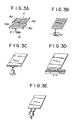
- Figures 3A, 3B, 3C, 3D and 3E are schematic views showing various embodiments of the movable grid drive mechanism used in the high-speed image recording apparatus in accordance with the present invention.
- FIG. 2 schematically shows an embodiment of the high-speed image recording apparatus for X-ray transmission images in accordance with the present invention.
- a high-speed image recording apparatus 1 comprises a first sheet receiving section 2 for receiving unused stimulable phosphor sheets, a second sheet receiving section 3 for receiving the stimulable phosphor sheets carrying X-ray transmission images stored therein, and a conveying mechanism for taking the stimulable phosphor sheets one by one out of the first sheet receiving section 2, sequentially conveying the stimulable phosphor sheets at high speeds to an image recording position, and then sequentially conveying the stimulable phosphor sheets carrying X-ray transmission images stored therein to the second sheet receiving section.
- a movable grid 4 is mounted in the image recording position so that the movable grid 4 intervenes between the stimulable phosphor sheet 5 fed to the image recording section and an object 20.
- a plurality of unused stimulable phosphor sheets 5a, 5b, 5c, ... are loaded in the bare form or in the form housed respectively in cassettes.
- the stimulable phosphor sheets in both forms are generically called stimulable phosphor sheets.
- the power of a motor 6 is transmitted to a conveying roller 8 via a clutch 7. Since the conveying roller 8 and guide rollers 9a to 9e are engaged with an endless conveyer belt 10, the conveyer belt 10 is moved in the direction of the arrow when the conveying roller 8 is rotated by the motor 6.
- the conveyer belt 10 releasably grasps, attracts or sucks the stimulable phosphor sheet 5a.
- the conveyer belt 10 may be provided with clamping claws for engagement with clamping pieces provided on the stimulable phosphor sheets, or may be provided with adhesive tapes.
- the conveyer belt 10 may be provided with female or male tapes of the face-to-face fastener type, and male or female tapes of this type may be provided on the stimulable phosphor sheets. Also, the conveyer belt 10 may be constructed to magnetically attract the stimulable phosphor sheets one by one.
- a limit switch 13 detects the arrival of the stimulable phosphor sheet 5, and the detection signal of the limit switch 13 is sent to a control section 14' in the apparatus.
- the clutch 7 is disengaged from the rotation of the motor 6, and a brake (not shown) is activated to stop the movement of the conveyer belt 10.
- X-rays are emitted from an X-ray generator 19 according to an instruction given by a control section 14 connected to the aforesaid control section 14' in the apparatus, and an image of the X-rays passing through the object 20 is projected onto the stimulable phosphor sheet 5 temporarily stopped as described above in the image recording position.
- a means for driving the movable grid 4 is activated in synchronization with the timing of image projection in a sequence programmed in advance in the control section 14.
- the movable grid 4 is hung from the body of the high-speed image recording apparatus via leaf springs 16a and 16b mounted on two opposed end portions of the movable grid 4, and a protrusion 17 of an iron core and a solenoid 15 for the iron core are positioned on another end portion of the movable grid 4.
- the solenoid 15 is energized by the signal sent from the control section 14 to attract the protrusion 17 of the iron core, thereby to hold the movable grid 4 at the start point of movement.
- a signal for releasing the movable grid 4 is sent to the solenoid 15 to have the movable grid 4 moved by the force of the leaf springs 16a and 16b. This operation is conducted each time an X-ray transmission image is projected onto the stimulable phosphor sheet.
- the projection start signal may be sent to the X-ray generator 19 a predetermined time after the releasing signal is sent to the solenoid 15.
- the movement of movable grid 4 should preferably be started a predetermined time before each image projection step is started, and then the movable grid 4 is held at the start point of movement after each image projection step is finished.
- the brake (not shown) is released by a completion signal, and the clutch 7 is connected to the motor 6.
- the second unused stimulable phosphor sheet 5b is conveyed to the image recording section and, at the same time, the stimulable phosphor sheet 5 carrying the X-ray transmission image stored therein is conveyed from the image recording section to the second sheet receiving section 3.
- the stimulable phosphor sheet 5 is disengaged from the conveyer belt 10 by a member 21 for releasing the grasping, attraction or sucking engagement between the stimulable phosphor sheet 5 and the conveyer belt 10, and then loaded into the second sheet receiving section 3.
- the movable grid 4 is attracted by the solenoid 15 for the next image recording step.
- the high-speed image recording apparatus may further be provided with a combination 22 of an X-ray image intensifier with a television camera in the position indicated by the chain line in Figure 2, so that the fluoroscopy can be conducted. Also, when a stimulable phosphor layer or stimulable phosphor layers are overlaid on the surface of the conveyer belt 10, instead of using the stimulable phosphor sheets, there become unnecessary the means for engagement of the conveyer belt 10 with the stimulable phosphor sheets, the solenoid 11 and the pressing piece 12.
- a cam mechanism as shown in Figure 3B, a combination of a DC servo motor or a stepping motor with a rack-and-pinion mechanism as shown in Figure 3C, a linear motor mechanism as shown in Figure 3D, or an eccentric motor as shown in Figure 3E.
- a cam mechanism as shown in Figure 3B, a combination of a DC servo motor or a stepping motor with a rack-and-pinion mechanism as shown in Figure 3C, a linear motor mechanism as shown in Figure 3D, or an eccentric motor as shown in Figure 3E.
- the movable grid 4 may be moved in any direction insofar as the generation of the fringes can be eliminated.
- the grid should preferably be moved in the direction normal to the longitudinal direction of the foil members (i.e. in the direction of the double directed arrow shown in Figure 1).
- the cross grid is swung in the direction of the diagonal line of the grating.
- the cross grid is made in the sector (fan-like) form, positioned above the stimulable phosphor sheet in parallel thereto, and rotated and reciprocated in parallel to the stimulable phosphor sheet around the rivet portion of the sector.
- the center of rotation is positioned above the stimulable phosphor sheet, there is a risk of moire fringes being generated at a portion of the stimulable phosphor sheet corresponding to the center of rotation of the cross grid. Therefore, the center of rotation of the cross grid should be positioned outside the stimulable phosphor sheet.
- the movable grid 4 In synchronization with the projection of the X-ray transmission image onto the stimulable phosphor sheet conveyed to the image recording position, the movable grid 4 is moved over a distance at least several times the space between the foil members of the movable grid 4 within the image projection time. Theoretically, generation of moire fringes can be eliminated when the movable grid 4 is moved a distance corresponding to one pitch of the foil members during the exposure to X-rays.
- the foil members are usually positioned in an amount within the range of 2.8 to 5.7 pcs./mm, the time required for the grid to move a distance corresponding to one pitch of the foil members becomes shorter than the exposure time. Further, it is not always possible to accurately move the grid a distance corresponding to one pitch of the foil members. In the experiments conducted by the inventors, satisfactory results were obtained when the movable grid 4 was moved a distance corresponding to five or six pitches of the foil members.
Landscapes
- Physics & Mathematics (AREA)
- General Physics & Mathematics (AREA)
- Health & Medical Sciences (AREA)
- Life Sciences & Earth Sciences (AREA)
- High Energy & Nuclear Physics (AREA)
- Molecular Biology (AREA)
- Spectroscopy & Molecular Physics (AREA)
- Radiography Using Non-Light Waves (AREA)
- Apparatus For Radiation Diagnosis (AREA)
Applications Claiming Priority (2)
| Application Number | Priority Date | Filing Date | Title |
|---|---|---|---|
| JP212236/82 | 1982-12-03 | ||
| JP57212236A JPS59102227A (ja) | 1982-12-03 | 1982-12-03 | 蓄積性螢光体シ−トを用いた高速撮影台 |
Publications (1)
| Publication Number | Publication Date |
|---|---|
| EP0114978A1 true EP0114978A1 (fr) | 1984-08-08 |
Family
ID=16619213
Family Applications (1)
| Application Number | Title | Priority Date | Filing Date |
|---|---|---|---|
| EP83112035A Withdrawn EP0114978A1 (fr) | 1982-12-03 | 1983-11-30 | Dispositif pour l'enregistrement rapide d'images au moyen d'un écran utilisant un phosphore stimulable |
Country Status (2)
| Country | Link |
|---|---|
| EP (1) | EP0114978A1 (fr) |
| JP (1) | JPS59102227A (fr) |
Cited By (6)
| Publication number | Priority date | Publication date | Assignee | Title |
|---|---|---|---|---|
| US4843240A (en) * | 1987-04-17 | 1989-06-27 | Fuji Photo Film Co., Ltd. | Radiation image recording and read-out apparatus |
| US4853540A (en) * | 1985-06-05 | 1989-08-01 | Fuji Photo Film Co., Ltd. | Apparatus for recording a radiation image of an object on a stimulable phosphor sheet to facilitate later reconstruction of an arbitrary tomographic image of the object |
| EP0179411B1 (fr) * | 1984-10-20 | 1990-01-10 | Fuji Photo Film Co., Ltd. | Appareil pour l'enregistrement et la lecture d'une image de radiation |
| US4982419A (en) * | 1988-03-19 | 1991-01-01 | Fuji Photo Film Co., Ltd. | Potter-bucky device |
| US5210416A (en) * | 1990-08-02 | 1993-05-11 | Fuji Photo Film Co., Ltd. | High-speed imaging stage |
| US6423979B1 (en) * | 1999-01-18 | 2002-07-23 | Fuji Photo Film Co., Ltd. | Transfer of stimulable phosphor sheet |
Families Citing this family (4)
| Publication number | Priority date | Publication date | Assignee | Title |
|---|---|---|---|---|
| JP2981706B2 (ja) * | 1992-10-19 | 1999-11-22 | 富士写真フイルム株式会社 | 放射線画像情報撮影台、放射線画像情報記録読取装置およびカセッテ |
| JP5808571B2 (ja) * | 2011-05-13 | 2015-11-10 | 富士フイルム株式会社 | 放射線撮影装置 |
| JP6139897B2 (ja) | 2013-02-05 | 2017-05-31 | キヤノン株式会社 | 画像解析装置、放射線撮影装置、画像解析方法、プログラムおよび記憶媒体 |
| EP3922179A1 (fr) * | 2020-06-08 | 2021-12-15 | Koninklijke Philips N.V. | Stratégie d'étape pour la compensation des défauts dans l'imagerie dax |
Citations (5)
| Publication number | Priority date | Publication date | Assignee | Title |
|---|---|---|---|---|
| US2467592A (en) * | 1943-07-22 | 1949-04-19 | Russell H Morgan | Driving mechanism for x-ray grids |
| GB802754A (en) * | 1956-05-02 | 1958-10-08 | Picker X Ray Corp Waite Mfg | Improvements relating to x-ray apparatus |
| US2938120A (en) * | 1957-12-02 | 1960-05-24 | Leslie M Forsyth | X-ray filter grid assembly and actuating means therefor |
| US4258264A (en) * | 1978-07-12 | 1981-03-24 | Fuji Photo Film Co., Ltd. | Method of and apparatus for reading out a radiation image recorded in a stimulable phosphor |
| EP0077676B1 (fr) * | 1981-10-16 | 1986-08-06 | Fuji Photo Film Co., Ltd. | Système d'enregistrement pour image de rayonnement |
-
1982
- 1982-12-03 JP JP57212236A patent/JPS59102227A/ja active Pending
-
1983
- 1983-11-30 EP EP83112035A patent/EP0114978A1/fr not_active Withdrawn
Patent Citations (5)
| Publication number | Priority date | Publication date | Assignee | Title |
|---|---|---|---|---|
| US2467592A (en) * | 1943-07-22 | 1949-04-19 | Russell H Morgan | Driving mechanism for x-ray grids |
| GB802754A (en) * | 1956-05-02 | 1958-10-08 | Picker X Ray Corp Waite Mfg | Improvements relating to x-ray apparatus |
| US2938120A (en) * | 1957-12-02 | 1960-05-24 | Leslie M Forsyth | X-ray filter grid assembly and actuating means therefor |
| US4258264A (en) * | 1978-07-12 | 1981-03-24 | Fuji Photo Film Co., Ltd. | Method of and apparatus for reading out a radiation image recorded in a stimulable phosphor |
| EP0077676B1 (fr) * | 1981-10-16 | 1986-08-06 | Fuji Photo Film Co., Ltd. | Système d'enregistrement pour image de rayonnement |
Cited By (6)
| Publication number | Priority date | Publication date | Assignee | Title |
|---|---|---|---|---|
| EP0179411B1 (fr) * | 1984-10-20 | 1990-01-10 | Fuji Photo Film Co., Ltd. | Appareil pour l'enregistrement et la lecture d'une image de radiation |
| US4853540A (en) * | 1985-06-05 | 1989-08-01 | Fuji Photo Film Co., Ltd. | Apparatus for recording a radiation image of an object on a stimulable phosphor sheet to facilitate later reconstruction of an arbitrary tomographic image of the object |
| US4843240A (en) * | 1987-04-17 | 1989-06-27 | Fuji Photo Film Co., Ltd. | Radiation image recording and read-out apparatus |
| US4982419A (en) * | 1988-03-19 | 1991-01-01 | Fuji Photo Film Co., Ltd. | Potter-bucky device |
| US5210416A (en) * | 1990-08-02 | 1993-05-11 | Fuji Photo Film Co., Ltd. | High-speed imaging stage |
| US6423979B1 (en) * | 1999-01-18 | 2002-07-23 | Fuji Photo Film Co., Ltd. | Transfer of stimulable phosphor sheet |
Also Published As
| Publication number | Publication date |
|---|---|
| JPS59102227A (ja) | 1984-06-13 |
Similar Documents
| Publication | Publication Date | Title |
|---|---|---|
| EP0162321B1 (fr) | Dispositif d'enregistrement d'image à haute vitesse pour traitement d'énergie par soustraction | |
| US4859849A (en) | Radiation image recording and read-out apparatus | |
| EP0114978A1 (fr) | Dispositif pour l'enregistrement rapide d'images au moyen d'un écran utilisant un phosphore stimulable | |
| US4853540A (en) | Apparatus for recording a radiation image of an object on a stimulable phosphor sheet to facilitate later reconstruction of an arbitrary tomographic image of the object | |
| DE3310093C2 (fr) | ||
| JPH0326809B2 (fr) | ||
| US5272025A (en) | Photograph and associated graphics with associated digitized formatting, and method of production and use thereof | |
| EP0098574B1 (fr) | Procédé et appareil pour la lecture d'images de radiation | |
| JPS6255128B2 (fr) | ||
| US5365076A (en) | Radiation image recording apparatus | |
| US5051589A (en) | Stimulable phosphor sheet and energy subtraction processing method using the same | |
| EP0098596B1 (fr) | Méthode et dispositif de reproduction d'images de rayonnement | |
| US4982419A (en) | Potter-bucky device | |
| JPH01154041A (ja) | 放射線診断装置 | |
| EP0179411B1 (fr) | Appareil pour l'enregistrement et la lecture d'une image de radiation | |
| US4167672A (en) | Method and apparatus for demonstration of arbitrary surfaces with dynamic tomography | |
| EP0140374A2 (fr) | Appareil d'enregistrement d'images à haute fréquence utilisant des feuilles en phosphore stimulable ainsi qu'enveloppes étanches à la lumière pour ces dernières | |
| JP2811250B2 (ja) | エネルギーサブトラクション用放射線画像撮影装置 | |
| JPH0584498B2 (fr) | ||
| JPS63210837A (ja) | 放射線撮影具 | |
| JPS63139851A (ja) | 画像記録担体の搬送方法および装置 | |
| JP2582580B2 (ja) | 放射線画像情報撮影装置 | |
| US4910531A (en) | Image recorder with a transformer having parallel leakage fluxes | |
| JPH02275582A (ja) | 放射線画像のエネルギーサブトラクション方法および装置 | |
| JPS60104936A (ja) | 蓄積性螢光体シ−トを用いた高速撮影台 |
Legal Events
| Date | Code | Title | Description |
|---|---|---|---|
| PUAI | Public reference made under article 153(3) epc to a published international application that has entered the european phase |
Free format text: ORIGINAL CODE: 0009012 |
|
| AK | Designated contracting states |
Designated state(s): DE FR NL |
|
| 17P | Request for examination filed |
Effective date: 19850130 |
|
| 17Q | First examination report despatched |
Effective date: 19860813 |
|
| STAA | Information on the status of an ep patent application or granted ep patent |
Free format text: STATUS: THE APPLICATION IS DEEMED TO BE WITHDRAWN |
|
| 18D | Application deemed to be withdrawn |
Effective date: 19870424 |
|
| RIN1 | Information on inventor provided before grant (corrected) |
Inventor name: OHGODA, MAKOTOC/O FUJI PHOTO FILM CO., LTD. Inventor name: KOMAKI, TAKAOC/O FUJI PHOTO FILM CO., LTD. |