EP0115025A2 - Capteur optique - Google Patents
Capteur optique Download PDFInfo
- Publication number
- EP0115025A2 EP0115025A2 EP83112820A EP83112820A EP0115025A2 EP 0115025 A2 EP0115025 A2 EP 0115025A2 EP 83112820 A EP83112820 A EP 83112820A EP 83112820 A EP83112820 A EP 83112820A EP 0115025 A2 EP0115025 A2 EP 0115025A2
- Authority
- EP
- European Patent Office
- Prior art keywords
- sensor
- sensor body
- measuring
- medium
- light
- Prior art date
- Legal status (The legal status is an assumption and is not a legal conclusion. Google has not performed a legal analysis and makes no representation as to the accuracy of the status listed.)
- Granted
Links
Images


Classifications
-
- G—PHYSICS
- G01—MEASURING; TESTING
- G01J—MEASUREMENT OF INTENSITY, VELOCITY, SPECTRAL CONTENT, POLARISATION, PHASE OR PULSE CHARACTERISTICS OF INFRARED, VISIBLE OR ULTRAVIOLET LIGHT; COLORIMETRY; RADIATION PYROMETRY
- G01J1/00—Photometry, e.g. photographic exposure meter
- G01J1/58—Photometry, e.g. photographic exposure meter using luminescence generated by light
-
- G—PHYSICS
- G01—MEASURING; TESTING
- G01D—MEASURING NOT SPECIALLY ADAPTED FOR A SPECIFIC VARIABLE; ARRANGEMENTS FOR MEASURING TWO OR MORE VARIABLES NOT COVERED IN A SINGLE OTHER SUBCLASS; TARIFF METERING APPARATUS; MEASURING OR TESTING NOT OTHERWISE PROVIDED FOR
- G01D5/00—Mechanical means for transferring the output of a sensing member; Means for converting the output of a sensing member to another variable where the form or nature of the sensing member does not constrain the means for converting; Transducers not specially adapted for a specific variable
- G01D5/26—Mechanical means for transferring the output of a sensing member; Means for converting the output of a sensing member to another variable where the form or nature of the sensing member does not constrain the means for converting; Transducers not specially adapted for a specific variable characterised by optical transfer means, i.e. using infrared, visible, or ultraviolet light
-
- G—PHYSICS
- G01—MEASURING; TESTING
- G01F—MEASURING VOLUME, VOLUME FLOW, MASS FLOW OR LIQUID LEVEL; METERING BY VOLUME
- G01F23/00—Indicating or measuring liquid level or level of fluent solid material, e.g. indicating in terms of volume or indicating by means of an alarm
- G01F23/22—Indicating or measuring liquid level or level of fluent solid material, e.g. indicating in terms of volume or indicating by means of an alarm by measuring physical variables, other than linear dimensions, pressure or weight, dependent on the level to be measured, e.g. by difference of heat transfer of steam or water
- G01F23/28—Indicating or measuring liquid level or level of fluent solid material, e.g. indicating in terms of volume or indicating by means of an alarm by measuring physical variables, other than linear dimensions, pressure or weight, dependent on the level to be measured, e.g. by difference of heat transfer of steam or water by measuring the variations of parameters of electromagnetic or acoustic waves applied directly to the liquid or fluent solid material
- G01F23/284—Electromagnetic waves
- G01F23/292—Light, e.g. infrared or ultraviolet
-
- H—ELECTRICITY
- H03—ELECTRONIC CIRCUITRY
- H03K—PULSE TECHNIQUE
- H03K17/00—Electronic switching or gating, i.e. not by contact-making and –breaking
- H03K17/94—Electronic switching or gating, i.e. not by contact-making and –breaking characterised by the way in which the control signals are generated
- H03K17/96—Touch switches
- H03K17/9627—Optical touch switches
- H03K17/9629—Optical touch switches using a plurality of detectors, e.g. keyboard
-
- H—ELECTRICITY
- H03—ELECTRONIC CIRCUITRY
- H03K—PULSE TECHNIQUE
- H03K17/00—Electronic switching or gating, i.e. not by contact-making and –breaking
- H03K17/94—Electronic switching or gating, i.e. not by contact-making and –breaking characterised by the way in which the control signals are generated
- H03K17/96—Touch switches
- H03K17/9627—Optical touch switches
- H03K17/9638—Optical touch switches using a light guide
-
- H—ELECTRICITY
- H03—ELECTRONIC CIRCUITRY
- H03M—CODING; DECODING; CODE CONVERSION IN GENERAL
- H03M11/00—Coding in connection with keyboards or like devices, i.e. coding of the position of operated keys
- H03M11/26—Coding in connection with keyboards or like devices, i.e. coding of the position of operated keys using opto-electronic means
Definitions
- the invention relates to an optical sensor for measuring, control and regulating arrangements and possible uses of such a sensor.
- Measurement and control technology has made great strides in recent years through the use of digital technology. In connection with this, an increasing number of precise and diverse sensors for physical quantities of all kinds is required. This development coincides with the introduction of the optical fiber with the associated optoelectronic transmission and reception elements as a new transmission medium.
- Their advantages are known: high bandwidth, electrical isolation, extensive insensitivity to electrical and magnetic interference fields and extreme temperatures, usability in explosive or corrosive environments, small space requirements, low weight. With the usual electronic sensors, these advantages can only be used if the sensor a converter is connected downstream, which converts the electrical output signal into an optical signal, which can then be transported via the fiber to the display unit or to the controller. So there is a double implementation here. For reasons of measurement accuracy, linearity and stability, there is therefore a need for sensors which convert the quantity to be measured directly into a suitable light signal.
- the invention is therefore based on the object of providing an optical sensor which optically detects a large number of physical variables which have an influence on the refractive index or the light transmittance of a comparison or measuring medium or of the sensor itself and emits them as optical signals.
- the combinations of features specified in claims 1 and 4 are proposed. Further advantageous refinements, developments and possible uses of the invention result from the subclaims.
- the luminescent particles arranged homogeneously distributed in an optical body emit their excitation energy in the form of light which is emitted equally distributed in all directions.
- a comparison or measuring medium is optically connected to a translucent boundary surface of the sensor body according to the invention, the luminescent light emitted inside the sensor body is at least partially reflected in accordance with the law of reflection and the law of refraction at the boundary surface of the sensor body and, if necessary, enters the other part with a change of direction Comparative or measuring medium. If light enters from an optically denser medium into a thinner medium, it will broken away from the plumb line.
- the angle of incidence exceeds a critical angle at which the refracted beam runs parallel to the boundary surface of the sensor body, total reflection occurs.
- the light emitted by the luminescent particles is only forwarded to the front ends in an elongated sensor body if its angle of incidence on the light-transmitting boundary surface is greater than the total reflection angle.
- Half of the total reflected luminescent light is directed to one of the two ends. The rest of the luminescent light escapes through the boundary surface into the neighboring comparison or measurement medium.
- abrupt changes in the refractive index of the comparison medium along the boundary surface of the sensor body can be determined in this way.
- This effect is particularly effective when a transition occurs between a comparison medium that is optically thinner than the sensor medium and an optically denser one at a certain point along the probe body.
- the area of the optically denser comparison medium almost all of the luminescent light that arises in the sensor body and arrives there is decoupled from the sensor body.
- the photoluminescence that is to say of the fluorescence or phosphorescence, which occurs when irradiated with light or ultraviolet radiation
- the sensors When selecting the sensor material, it is fundamentally possible to use materials that are also used for fluorescence collectors.
- the sensors have an elongated cylindrical, plate-like or foil-like shape, the transverse dimension of which is small compared to their length.
- the jacket or broad side surface of the sensor body forms the translucent boundary surface to which the comparison or measurement medium is optically connected.
- the primary light source should have a light intensity such that the majority of the fluorescent or phosphorescent particles in the sensor body can be excited with it.
- pulsed operation is also possible, for example to eliminate extraneous light interference.
- care should be taken to ensure that the existing fluorescent particles are activated as completely as possible.
- the light supply to the entry point as well as the signal transport from the measuring point can take place with the aid of optical fibers.
- the optical signals can be converted into electrical signals using any photo receiver, for example a photo diode, a photo transistor, a photo resistor or a photo element.
- the entry point for the primary light and the measurement point for the fluorescent light at the same end of the sensor are arranged body and that the end face at the other end of the sensor body is translucent.
- the entry point and the measuring point can be arranged together on an end boundary surface, for example laterally next to one another or coaxially to one another.
- the measuring point can also be formed by a coupling-out prism or a coupling-out grating arranged on the lateral surface of the sensor.
- the intensity of the luminescent light emerging at the measuring point can in principle also be influenced in that the entry surface of the sensor body is more or less covered or shadowed from the primary light.
- the sensor body according to the invention can be used largely independently of the refractive index of the surrounding medium achieve intensity changes in the luminescent radiation due to the variable covering area or light transmittance of a screen arranged in the beam path of the primary light, which changes can be used for position measurements, for example for level measurements in liquid containers.
- a screen arranged in the beam path of the primary light with electrically controllable light transmission for example with locally controllable liquid crystal regions between crossed or uncrossed polarizer plates, an electro-optical signal conversion is possible in a simple manner.
- the decrease in intensity of the luminescent light within the sensor body on the path between the entry point of the primary light and the measuring point is used for position measurements.
- a bundled primary light beam is used, which, depending on the size to be measured, is directed at a variable distance from the measuring point onto the surface of the elongated sensor body.
- the light intensity recorded at the measuring point is here a function of the distance from the entry point of the primary light and, if appropriate, the number and position of the primary light sources arranged at a distance from one another.
- a window in the entry surface of the sensor body can be assigned to each primary light source.
- the sensors 10 shown in the drawing consist of an optical body 12 made of translucent material, in which luminescent particles 14 (luminophores) are arranged as homogeneously as possible over the volume.
- the luminescent particles are brought into an excited state by irradiation with light, ultraviolet, X-ray, gamma or corpuscular rays, by chemical processes, by the action of electrical fields or by electrical discharge processes and return to their ground state with emission of light, infrared or ultraviolet radiation back.
- the sensors described below use only the photoluminescence, that is to say the fluorescence or phosphorescence, which occurs when irradiated with light or ultraviolet radiation, although the other types of luminescence would in principle also be applicable.
- the only decisive factor in this connection is the fact that the light is emitted by the totality of the luminescent particles in all directions, evenly distributed.
- a comparison or measuring medium L, W with a refractive index n a is optically connected to a transparent boundary surface 16 of the sensor body 12, the refractive index of which is n i , the luminescent light is switched on the boundary surface 16 of the sensor body 12 in accordance with the law of reflection and Snellius' law of refraction at least partially reflected and possibly exits the other part with a change of direction in the comparison or measuring medium L, W.
- ⁇ i and ⁇ a mean the angle of incidence with respect to the perpendicular in the sensor body (i) or in the comparison or measuring medium (a).
- the light emitted by the luminescent particles is then only increased in an elongated sensor body 12 the front ends 18, 20 if its angle of incidence ⁇ i at the translucent boundary surfaces 16 is greater than the total reflection angle ⁇ t .
- All other luminescent light is of the order of magnitude after a relatively short distance where d is the diameter or the wall thickness of the sensor body 12, through the boundary surface into the comparison or measuring medium L, W. Light conduction therefore only occurs if the comparison or measurement medium is optically thinner than the sensor medium.
- the luminescent light is emitted equally distributed in all directions and is only slightly absorbed in a suitable sensor material, it is possible with a given geometry of a sensor body and with a known refractive index of the sensor medium and the comparison or measuring medium due to the above physical laws, the proportion of within Specify the luminescent light produced by the sensor body, which reaches the two ends 18, 20 of the sensor body.
- This proportion is for an elongated cylindrical rod and in the case of an elongated plate-shaped body with plane-parallel boundary surfaces 16 and mirrored longitudinal side edges 22
- Half of this portion is directed to one of the two ends 18, 20.
- the rest of the luminescent light escapes via the boundary surface 16 into the adjacent comparison or measuring medium L, W.
- the intensity of the luminescent light occurring in a cross-sectional area, in particular in the vicinity of the front ends 18, 20 of the sensor body 12, forms an easily measurable quantity which, depending on the application, can be used as a measure for various influencing parameters.
- This intensity measurement variable can be influenced above all by changing the ratio of the refractive indices n i , n a between the sensor medium on the one hand and the adjacent comparison and / or measurement media on the other. In particular, sudden changes in the refractive index n of the comparison medium along the sensor body 12 can be determined in this way.
- This effect is particularly effective when a transition 23 occurs at a certain point along the sensor body 12 between a comparison medium that is optically thinner than the sensor medium and optically denser.
- a comparison medium that is optically thinner than the sensor medium and optically denser.
- W approximately all of the luminescent light that arises in the sensor body 12 and arrives there is decoupled from the sensor body 12.
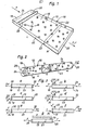
- the exemplary embodiments shown in FIGS. 1 and 2 are optical sensors 10, which can be used above all for level measurement in liquid containers.
- the sensors 10 consist of an elongated plate-shaped or film-shaped (FIG. 1) or cylindrical (FIG. 2) probe made of translucent material, in which fluorescent particles are arranged distributed over the volume.
- primary light P is supplied with such an intensity and wavelength that the majority of the fluorescent particles 14 contained in the probe are excited to emit light.
- the probe also contains a measuring point 26 at which the fluorescent light reaching this point is coupled out and fed to a photo receiver.
- Photodiodes, photo transistors, photo resistors or photo elements are suitable as photo receivers, for example, which convert the incoming signals into electrical signals so that they can be further processed electronically for display and control purposes.
- One end of the probe is expediently immersed in the liquid W up to the bottom of the container, so that a part of the probe survives above the liquid level 23.
- the entry point 24 for the primary light P and the measuring point 26 for the fluorescent light F are in the region of the end 18 of the probe which is not immersed in the liquid, that is to say in the optically thinner comparison medium, for example air L.
- the other end 20 of the probe ends with a translucent frontal boundary surface at the lowest point of the container, so that the primary light P which is fed in at the entry point 24 and which is not used for fluorescence processes can exit undisturbed.
- the fluorescent light guided in this direction by total reflection also emerges at the lower end 20 of the probe.
- the fluorescent light emitted in the opposite direction and guided in the probe by total reflection is coupled out of the probe body 12 at the upper end, for example through a prism 28 or a grating, and fed to the photo receiver.
- the refractive index n i of the probe body 12 is smaller than that of the liquid W, then practically no fluorescent light reaches the measuring point from the immersed area of the probe, since the fluorescent light produced there escapes almost completely into the liquid W.
- fluorescent light comes exclusively from the non-immersed part of the probe to the measuring point 26 if it is assumed that the refractive index of the comparison medium (air) is smaller than that of the probe.
- the refractive index of the liquid W is smaller than that of the probe medium, but larger than that of the air L-iat.
- part of the fluorescent light produced in the immersed area is also directed to the measuring point 26 by total reflection.
- this part is smaller than the corresponding part from the non-immersed area, so that here too a change in the fill level results in a change in intensity of the measured fluorescent light.
- Primary light P and the measuring point for the connection of the photoreceiver are arranged coaxially to one another at one of the end ends 18 of the probe. Since the opposite end of the probe end 20 is translucent, only such fluorescent light reaches the measuring point 26 that emits against the radiation direction of the primary light P from the fluorescent particles 14 and is totally reflected on the cylindrical boundary surface 16.
- FIGS. 3a to g show some further probe variants with a different arrangement of the entry points 24 and the measuring points 26.
- the primary light P is compared to that of the measuring point 26 lying end 20 in the region of the denser comparison medium W.
- the primary light P reaches the measuring point directly together with the fluorescent light to be measured, while in the case of FIG. 3b most of the primary light P can emerge from the translucent face 18, but to a lesser extent is coupled out via the prism 28 F at the measuring point 26 with the fluorescent light.
- additional precautions for a separation of these two light components are necessary, which will not be discussed in more detail here.
- FIGS. 3e, f and g A significant improvement in this regard is achieved with the exemplary embodiments shown in FIGS. 3e, f and g, in which care is taken to ensure that the excess primary light cannot reach the measuring point 26 due to the light guidance within the probe.
- the entry point 24 and the measuring point 26 are located next to one another at one end 18 of the probe, while the other end 20 is permeable to the passage of the primary light and the portion of the fluorescent light that reaches it.
- the primary light is fed in on one end face 18 and occurs on the other end face 20 together with the one reaching there Fluorescence light off, while the fluorescence light emitted in the opposite direction is in turn coupled out through a prism 28.
- the primary light P is supplied transversely to the longitudinal extent of the probe via its jacket or broad side surface 16 and emerges again from the probe body on the broad side opposite this.
- measurement points for the F luores- zenzander can be provided, which does not enter primary light at two ends.
- At least one coupling prism is arranged to be longitudinally displaceable on an elongated optical sensor 10 of the type described above.
- the base length of the coupling prism should be of the order of magnitude at least the response length.
- a dx tan ⁇ t , where ⁇ t is the total reflection angle of the sensor body 12 with respect to the surrounding air.
- the fluorescent light is decoupled via the hypotenuse surface of the prisms 30, so that a directional dependence of the decoupled light is obtained.
- the primary light P can be irradiated either via one of the end faces 18, 20 or, as indicated in FIG. 4, via the jacket or broad side surface 16 of the sensor body.
- the measuring points 26 for the fluorescent light are expediently arranged at the front ends 18, 20 of the sensor body.
- the intensity of the fluorescent light arriving at the measuring points 26 and their ratio or difference form dimensions for the position of the coupling prisms relative to one another and to the measuring points.
- the individual keys 32 which are arranged at a distance from one another along the sensor bodies 12 designed as elongated light guides, are connected to the said decouplers, which are pressed against the transparent boundary surface 16 of the sensor body 12 when the keys 32 are struck .
- the fluorescent light reaching the measuring points 26 at the front ends 18, 20 is weakened in a defined manner in accordance with the momentarily pressed key.
- intensity measurements at each of the two measuring points 26 it can thus be determined whether and, if so, which keys 32 are pressed. It can also be monitored by comparing the measurement results of both measuring points or by adding up whether two keys are pressed at the same time.
- a time overlap of the pressing of two keys can be eliminated in terms of circuitry, since it can be determined in each case which key is struck first and which is struck last.
- FIG. 5 there are several sensor bodies 12 equipped with separate measuring points 26 provided for one key group each, while in the exemplary embodiment according to FIG. 6 there is a single elongated sensor body 12 with a plurality of light-guiding bends 34 for the entire key field.
- the primary light radiation P occurs in each case via the jacket or broad side surfaces 16 of the sensor body 12, so that no primary light can reach the measuring points 26.
- the sensor arrangements shown in FIGS. 7 and 8 work according to the shading principle.
- the sensor 10 again consists of a rod-shaped or plate-shaped body 12 made of translucent material, in which photoluminescent particles 14 are arranged homogeneously distributed over the volume.
- the excitation of the luminescent particles takes place via the primary light P, which is fed transversely to the longitudinal extent of the probe via its broad side surface 16 and emerges again from the probe body on the opposite broad side.
- the luminescent light can be received at measuring points 26 at the front ends 18, 20 of the probe body.
- a cover 40 or 42 for example in the form of a screen, which has at least one opaque shading area 44.
- the size of the shading area is variable and can.
- a variable to be measured for example by the level in a container.
- a variable to be measured for example by the level in a container.
- more or fewer luminescent particles are excited in the probe body by the primary light, so that the light intensity received at the measuring points 26 is a measure of the size of the shading area and thus of the measurement variable to be determined.
- the shading screen 42 is in the form of a liquid crystal arrangement formed, which consists of two polarizers 46,48 and a liquid crystal layer arranged between the polarizers.
- the liquid crystal layer can be electrically controlled separately in a plurality of regions 44 arranged distributed over the screen surface, so that largely any permeability profiles can be generated over the screen surface.
- the light intensity measured at the ends of the probe body is thus a measure of the effective permeability of the LCD screen.
- the decrease in intensity of the luminescent light due to light absorption on the path between the point of generation of the luminescent light and the measuring points 26 is used to determine the relative position of the primary light sources 50 along the elongated sensor body.
- the primary light sources 50 emit a bundled primary light beam P, which is directed perpendicular to the longitudinal extent of the sensor body 12 onto the entry surface 16.
- the primary light source 50 and the sensor body 12 can be arranged so as to be displaceable relative to one another, as is indicated in FIG. 9 by the double arrow 52.
- a plurality of primary light sources 50 which are spaced apart from one another are arranged in a fixed association with the sensor body 12.
- the entrance surface 16 of the sensor body is provided with a plurality of translucent windows 54 facing the primary light sources 50, while the intermediate areas 56 between the windows 54 are opaque.
- Each primary light source 50 alone or in combination with other primary light sources 50, produces a defined intensity of the luminescent light at the location of the measuring points, which allows a positional determination by measurement.
- the sensor body was fastened at its two ends on a pad provided with millimeter graduation on a board in such a way that a light-tight sleeve closed on one side could be moved on the sensor body and thus left different lengths open for the incidence of light. Diffuse daylight striking the long side of the sensor body was used as the primary light source.
- the arrangement essentially corresponded to the exemplary embodiment according to FIG. 7, in which a single phototransistor is arranged at the right end of the sensor body.
- the emitter-collector section of the phototransistor was connected in series with a reference resistor of 220 kohm to a DC voltage source of 9 volts.
- the voltage present at the reference resistor was measured with a digital voltmeter depending on the free length of the sensor body exposed to primary light.
- M were eating results:
- the measurement results show a sensitive, constant dependency between the light-exposed free length of the sensor body and the voltage picked up on the digital voltmeter and corresponding to the fluorescent light signal.
Landscapes
- Physics & Mathematics (AREA)
- General Physics & Mathematics (AREA)
- Electromagnetism (AREA)
- Engineering & Computer Science (AREA)
- Thermal Sciences (AREA)
- Fluid Mechanics (AREA)
- Spectroscopy & Molecular Physics (AREA)
- Theoretical Computer Science (AREA)
- Investigating Or Analysing Materials By Optical Means (AREA)
- Investigating, Analyzing Materials By Fluorescence Or Luminescence (AREA)
- Investigating Or Analysing Materials By The Use Of Chemical Reactions (AREA)
- Glass Compositions (AREA)
- Gyroscopes (AREA)
- Photometry And Measurement Of Optical Pulse Characteristics (AREA)
Priority Applications (1)
| Application Number | Priority Date | Filing Date | Title |
|---|---|---|---|
| AT83112820T ATE34611T1 (de) | 1982-12-23 | 1983-12-20 | Optischer sensor. |
Applications Claiming Priority (2)
| Application Number | Priority Date | Filing Date | Title |
|---|---|---|---|
| DE19823247659 DE3247659A1 (de) | 1982-12-23 | 1982-12-23 | Optischer sensor |
| DE3247659 | 1982-12-23 |
Publications (3)
| Publication Number | Publication Date |
|---|---|
| EP0115025A2 true EP0115025A2 (fr) | 1984-08-08 |
| EP0115025A3 EP0115025A3 (en) | 1984-12-12 |
| EP0115025B1 EP0115025B1 (fr) | 1988-05-25 |
Family
ID=6181526
Family Applications (1)
| Application Number | Title | Priority Date | Filing Date |
|---|---|---|---|
| EP83112820A Expired EP0115025B1 (fr) | 1982-12-23 | 1983-12-20 | Capteur optique |
Country Status (5)
| Country | Link |
|---|---|
| US (1) | US4650992A (fr) |
| EP (1) | EP0115025B1 (fr) |
| JP (1) | JPS59133438A (fr) |
| AT (1) | ATE34611T1 (fr) |
| DE (2) | DE3247659A1 (fr) |
Cited By (7)
| Publication number | Priority date | Publication date | Assignee | Title |
|---|---|---|---|---|
| FR2577317A1 (fr) * | 1985-02-08 | 1986-08-14 | Inst Rech Hydrologique | Appareil de mesure de la turbidite d'un liquide en flux continu. |
| WO1988001738A1 (fr) * | 1986-09-03 | 1988-03-10 | Wolfgang Ruhrmann | Detecteur opto-electronique |
| WO1988004414A1 (fr) * | 1986-12-08 | 1988-06-16 | The General Electric Company, P.L.C. | Dispositif de mesure des radiations |
| FR2628836A1 (fr) * | 1988-03-18 | 1989-09-22 | Veglia Borletti Srl | Procede de mesure du niveau de liquide dans un reservoir et capteur realisant un tel procede |
| EP0361374A3 (en) * | 1988-09-28 | 1990-05-30 | Hoechst Aktiengesellschaft | Light-detecting device |
| EP0229307B1 (fr) * | 1985-12-09 | 1991-05-29 | Siemens Aktiengesellschaft | Dispositif pour l'interprétation de la position et de l'intensité d'un spot lumineux |
| WO1993005365A1 (fr) * | 1991-09-09 | 1993-03-18 | Welmed Limited | Transmission de donnees |
Families Citing this family (26)
| Publication number | Priority date | Publication date | Assignee | Title |
|---|---|---|---|---|
| DE3413372A1 (de) * | 1984-04-10 | 1985-10-17 | Ruhrmann, Wolfgang, Dr., 7000 Stuttgart | Flaechendetektor, insbesondere zielscheibe |
| DE3441498A1 (de) * | 1984-11-09 | 1986-05-15 | Licentia Patent-Verwaltungs-Gmbh, 6000 Frankfurt | Verfahren und anordnung zur erfassung der position von lichtstrahlen |
| US4763973A (en) * | 1985-02-27 | 1988-08-16 | Omron Tateisi Electronics Co. | Waveguide-type optical sensor |
| DE3511757A1 (de) | 1985-03-30 | 1986-10-02 | Fraunhofer Ges Forschung | Vorrichtung zur bestimmung der position eines eine lichtquelle aufweisenden positionsgebers |
| US4733929A (en) * | 1986-02-05 | 1988-03-29 | Brown David C | Diffuser fiber incident energy concentrator and method of using same |
| US4884860A (en) * | 1986-02-05 | 1989-12-05 | Brown David C | Linear lens and method for concentrating radiant energy and multiplying phosphor luminance output intensity |
| DE3644866A1 (de) * | 1986-09-03 | 1988-03-17 | Wolfgang Dr Ruhrmann | Sensor |
| DE3712699A1 (de) * | 1987-04-14 | 1988-11-03 | Wolfgang Dr Ruhrmann | Sensor |
| GB8728272D0 (en) * | 1987-12-03 | 1988-01-06 | Pilkington Plc | Method of producing surface microstructure on glass |
| US4942306A (en) * | 1988-12-30 | 1990-07-17 | Focal Technologies Incorporated | Fibre optic sensor for the continuous measurement liquids level and other parameters |
| FR2634031A1 (fr) * | 1988-07-05 | 1990-01-12 | Commissariat Energie Atomique | Dispositif de multiplexage en longueur d'onde utilisant une fibre optique |
| US5173434A (en) * | 1990-11-05 | 1992-12-22 | Baxter Diagnostics Inc. | Measurement of color reactions by monitoring a change of fluorescence |
| DE69032810T2 (de) * | 1989-01-03 | 1999-06-17 | Marcos Y Kleinerman | Fernmessung physikalischer Variablen mit faseroptischen Systemen |
| FR2642836B1 (fr) * | 1989-01-18 | 1991-05-17 | Jaeger | Capteur de deplacement |
| NL9002211A (nl) * | 1990-10-11 | 1992-05-06 | Philips Nv | Positiegevoelig stralingsdetektiestelsel en optische aftastinrichting daarvan voorzien. |
| US5942748A (en) * | 1993-09-09 | 1999-08-24 | The United States Of America As Represented By The Secretary Of The Navy | Liquid level sensor and detector |
| US5416863A (en) * | 1993-12-30 | 1995-05-16 | At&T Corp. | Mode-field transforming optical waveguide |
| US6173609B1 (en) | 1997-06-20 | 2001-01-16 | Optical Sensor Consultants, Inc. | Optical level sensor |
| US6172377B1 (en) * | 1998-10-28 | 2001-01-09 | Sandia Corporation | Fluorescent optical liquid level sensor |
| US6293143B1 (en) * | 2000-03-23 | 2001-09-25 | Lexmark International, Inc. | Ink level sensing device and method therefor |
| AU2003249274A1 (en) * | 2002-07-16 | 2004-02-02 | Strube, Inc. | Liquid level sensor using fluorescence in an optical waveguide |
| US20040178345A1 (en) * | 2003-03-10 | 2004-09-16 | Kavlico Corporation | Efficient position sensing system |
| US8791645B2 (en) | 2006-02-10 | 2014-07-29 | Honeywell International Inc. | Systems and methods for controlling light sources |
| US8362436B1 (en) | 2006-03-14 | 2013-01-29 | Advanced Precision Inc. | Electro-optic fluid quantity measurement system |
| WO2013154917A1 (fr) | 2012-04-12 | 2013-10-17 | 3M Innovative Properties Company | Capteur à fibres optiques fluorescent |
| AT517348B1 (de) * | 2015-11-06 | 2017-01-15 | Isiqiri Interface Tech Gmbh | Vorrichtung und Verfahren zur Augenüberwachung |
Family Cites Families (34)
| Publication number | Priority date | Publication date | Assignee | Title |
|---|---|---|---|---|
| US2569127A (en) * | 1946-07-06 | 1951-09-25 | Shell Dev | Refractive index measurement of fluids |
| GB859104A (en) * | 1958-04-10 | 1961-01-18 | Bendix Corp | Level sensors |
| DE1211421C2 (de) * | 1963-12-12 | 1973-11-15 | Vorrichtung zur abtastung von durchlaufendem gut | |
| GB1137475A (en) * | 1966-01-13 | 1968-12-18 | Rosemount Eng Co Ltd | Improvements in or relating to radiation responsive devices |
| GB1250603A (fr) * | 1967-10-18 | 1971-10-20 | ||
| DE1755074B1 (de) * | 1968-03-27 | 1970-09-10 | Eltro Gmbh | Anzeigevorrichtung fuer das Verschmutzen und Beschlagen von Fenstern |
| US3557619A (en) * | 1969-03-17 | 1971-01-26 | Phys Chemical Research Corp | Humidity measuring method and apparatus |
| DE2034344A1 (de) * | 1970-07-10 | 1972-01-13 | Ulrich H | Einrichtung zur Messung physikalischer Großen durch Messung der Intensität eines Lichtstrahlenbundels |
| US3745359A (en) * | 1971-03-22 | 1973-07-10 | Picker Corp | Scintillation crystal with reflection inhibiting material and scintillation device embodying the crystal |
| FR2213487B1 (fr) * | 1972-11-07 | 1975-03-14 | British Petroleum Co | |
| US3856404A (en) * | 1973-06-06 | 1974-12-24 | Phys Chem Res Corp | Method and apparatus for measuring vapor pressure |
| US3893339A (en) * | 1974-03-18 | 1975-07-08 | Illinois Tool Works | Liquid level indicator |
| DE2420594A1 (de) * | 1974-04-27 | 1975-11-06 | Bernd Ing Grad Korndoerfer | Vollautomatische scheibenwischersteuerung fuer kraftfahrzeuge |
| US3934148A (en) * | 1974-05-28 | 1976-01-20 | Collins William O | Fluorescent plastic controlled direction lamp |
| GB1507747A (en) * | 1975-08-21 | 1978-04-19 | Standard Telephones Cables Ltd | Immiscible liquids measurement |
| DE2717133A1 (de) * | 1977-04-19 | 1978-11-02 | Kloeckner Humboldt Deutz Ag | Vorrichtung zur anzeige des fluessigkeitsstandes in einem behaelter |
| AU4223778A (en) * | 1977-12-12 | 1979-06-21 | Pedro B Macedo | Optical waveguide sensor |
| DE2920199A1 (de) * | 1978-05-31 | 1979-12-06 | Eaton Sa Monaco | Fluessigkeitsniveau-anzeigevorrichtung |
| US4151747A (en) * | 1978-06-21 | 1979-05-01 | Electric Power Research Institute, Inc. | Monitoring arrangement utilizing fiber optics |
| DE2906280A1 (de) * | 1979-01-31 | 1980-08-07 | Bbc Brown Boveri & Cie | Verfahren zur optischen erfassung und uebertragung des messwertes einer temperatur, eines druckes oder eines bewegungsvorganges |
| SE7903175L (sv) * | 1979-04-10 | 1980-10-11 | Asea Ab | Fiberoptiskt metdon |
| US4443699A (en) * | 1979-08-31 | 1984-04-17 | The Johns Hopkins University | Fluid level measuring device with linear, high resolution output |
| US4288159A (en) * | 1979-10-01 | 1981-09-08 | The Yellow Springs Instrument Company, Inc. | Optical temperature transducer |
| EP0029653B1 (fr) * | 1979-11-21 | 1983-06-01 | THE GENERAL ELECTRIC COMPANY, p.l.c. | Systèmes optiques pour capter et mesurer des grandeurs physiques |
| SE418904B (sv) * | 1979-12-28 | 1981-06-29 | Asea Ab | Fiberoptiskt metdon for metning av fysikaliska storheter sasom lege, hastighet, acceleration, kraft, tryck, tojning och temperatur |
| SE420130B (sv) * | 1980-01-24 | 1981-09-14 | Asea Ab | Optiskt metdon for metning av kraft eller tryck |
| US4371897A (en) * | 1980-09-02 | 1983-02-01 | Xerox Corporation | Fluorescent activated, spatially quantitative light detector |
| SE423752B (sv) * | 1980-09-29 | 1982-05-24 | Asea Ab | Optiskt sensorelement |
| SE436800B (sv) * | 1980-11-06 | 1985-01-21 | Asea Ab | Optiskt sensorelement av fast material for avkenning av fysikaliska storheter, sasom tryck, vilket exciteras optiskt och avger fotoluminiscens |
| US4403826A (en) * | 1981-03-23 | 1983-09-13 | Bell Telephone Laboratories, Incorporated | Ultraviolet radiation detector |
| GB2097528B (en) * | 1981-04-29 | 1985-02-06 | Ferranti Ltd | Position sensing apparatus |
| DE3119570A1 (de) * | 1981-05-16 | 1982-12-02 | Fa. Carl Zeiss, 7920 Heidenheim | Fluoreszierendes material enthaltender strahlungssensor |
| SE435967B (sv) * | 1982-04-01 | 1984-10-29 | Asea Ab | Fiberoptiskt luminiscensmetdon |
| SE431128B (sv) * | 1982-05-27 | 1984-01-16 | Asea Ab | Fiberoptisk sensor med atomert lokaliserade luminiscenscentra fiberoptisk sensor med atomert lokaliserade luminiscenscentra |
-
1982
- 1982-12-23 DE DE19823247659 patent/DE3247659A1/de not_active Withdrawn
-
1983
- 1983-12-20 EP EP83112820A patent/EP0115025B1/fr not_active Expired
- 1983-12-20 DE DE8383112820T patent/DE3376759D1/de not_active Expired
- 1983-12-20 AT AT83112820T patent/ATE34611T1/de not_active IP Right Cessation
- 1983-12-20 US US06/563,672 patent/US4650992A/en not_active Expired - Fee Related
- 1983-12-23 JP JP58242289A patent/JPS59133438A/ja active Pending
Cited By (12)
| Publication number | Priority date | Publication date | Assignee | Title |
|---|---|---|---|---|
| FR2577317A1 (fr) * | 1985-02-08 | 1986-08-14 | Inst Rech Hydrologique | Appareil de mesure de la turbidite d'un liquide en flux continu. |
| EP0229307B1 (fr) * | 1985-12-09 | 1991-05-29 | Siemens Aktiengesellschaft | Dispositif pour l'interprétation de la position et de l'intensité d'un spot lumineux |
| WO1988001738A1 (fr) * | 1986-09-03 | 1988-03-10 | Wolfgang Ruhrmann | Detecteur opto-electronique |
| US4936681A (en) * | 1986-09-03 | 1990-06-26 | Wolfgang Ruhrmann | Optical sensor |
| WO1988004414A1 (fr) * | 1986-12-08 | 1988-06-16 | The General Electric Company, P.L.C. | Dispositif de mesure des radiations |
| US4935631A (en) * | 1986-12-08 | 1990-06-19 | The General Electric Company, P.L.C. | Radiation meters |
| AU601798B2 (en) * | 1986-12-08 | 1990-09-20 | General Electric Company, Plc, The | Radiation meters |
| GB2198530B (en) * | 1986-12-08 | 1991-04-17 | Gen Electric Plc | Radiation meters |
| FR2628836A1 (fr) * | 1988-03-18 | 1989-09-22 | Veglia Borletti Srl | Procede de mesure du niveau de liquide dans un reservoir et capteur realisant un tel procede |
| EP0361374A3 (en) * | 1988-09-28 | 1990-05-30 | Hoechst Aktiengesellschaft | Light-detecting device |
| WO1993005365A1 (fr) * | 1991-09-09 | 1993-03-18 | Welmed Limited | Transmission de donnees |
| US5561732A (en) * | 1991-09-09 | 1996-10-01 | Coventry Univ. Enterprises & Welmed Ltd. | Data transmission |
Also Published As
| Publication number | Publication date |
|---|---|
| ATE34611T1 (de) | 1988-06-15 |
| DE3376759D1 (en) | 1988-06-30 |
| EP0115025B1 (fr) | 1988-05-25 |
| JPS59133438A (ja) | 1984-07-31 |
| US4650992A (en) | 1987-03-17 |
| DE3247659A1 (de) | 1984-06-28 |
| EP0115025A3 (en) | 1984-12-12 |
Similar Documents
| Publication | Publication Date | Title |
|---|---|---|
| EP0115025A2 (fr) | Capteur optique | |
| EP0163847B1 (fr) | Réfractomètre interférométrique | |
| DE60013258T2 (de) | Faseroptischer sensor mit photochromatischem wandler und methode zu seiner anwendung | |
| EP0777119A2 (fr) | Appareil pour des mesures de réflexion de la lumière | |
| DE69816809T2 (de) | Vorrichtung für fluoreszenznachweis | |
| EP0078939B1 (fr) | Dispositif en forme de bâton pour détecter le niveau respectif de liquides dans des récipients, des canaux ou similaires | |
| DE10035263C2 (de) | Optische Vorrichtung | |
| DE19621584A1 (de) | Optischer Sensor unter Verwendung mit seltenen Erdmetallen dotierter Laser mit integrierter Optik | |
| EP2520924A1 (fr) | Procédé et agencement de mesure pour l'amélioration de la dissolution de signal dans la spectroscopie d'absorption de gaz | |
| DE102012018303A1 (de) | Messgerät zur Lumineszenzmessung | |
| EP0116131A2 (fr) | Transducteur à fibres optiques | |
| DE102017128290B4 (de) | Messvorrichtung und Messsystem zur Bestimmung des pH-Wertes und Verfahren zum Bestimmen des pH-Wertes | |
| DE68907570T2 (de) | Fühlereinrichtung mit optischen Fasern. | |
| DE3441498C2 (fr) | ||
| WO1988001738A1 (fr) | Detecteur opto-electronique | |
| DE60018065T2 (de) | Kontinuierlich verlängerte optische quellen und empfänger und optische barriere mit solchen quellen und empfänger | |
| DE2657851A1 (de) | Vorrichtung zum kontinuierlichen messtechnischen erfassen der verschmutzung einer waessrigen fluessigkeit durch oel | |
| DE10221823A1 (de) | Verfahren und Vorrichtung zur Messung der Höhe des Flüssigkeitsniveaus und des Verunreinigungsgrades von Wassern und anderen transparenten Flüssigkeiten | |
| DE2840867C2 (de) | Gasmeßvorrichtung mit einem von dem nachzuweisenden Gas durchströmten Prüfröhrchen | |
| DE3908548A1 (de) | Verfahren zur messung des fluessigkeitsstandes in einem behaelter und messfuehler zur durchfuehrung des verfahrens | |
| DE10354856A1 (de) | Verfahren und Anordnung zur Bestimmung von Veränderungen der Oberflächenspannung sowie zur Ermittlung des Niveaus transparenter Fluide | |
| DE3336210A1 (de) | Verfahren und vorrichtung zur fuellstandsmessung | |
| EP2619551A1 (fr) | Capteur destiné à la surveillance d'un milieu | |
| DE4240804C2 (de) | Einrichtung zum Erkennen der Lage und/oder zum Messen der Breite eines Aufzeichnungsträgers | |
| WO2004070369A1 (fr) | Procede et dispositifs permettant de determiner et surveiller des etats d'impuretes dans differents fluides |
Legal Events
| Date | Code | Title | Description |
|---|---|---|---|
| PUAI | Public reference made under article 153(3) epc to a published international application that has entered the european phase |
Free format text: ORIGINAL CODE: 0009012 |
|
| AK | Designated contracting states |
Designated state(s): AT CH DE FR GB LI NL SE |
|
| PUAL | Search report despatched |
Free format text: ORIGINAL CODE: 0009013 |
|
| AK | Designated contracting states |
Designated state(s): AT CH DE FR GB LI NL SE |
|
| 17P | Request for examination filed |
Effective date: 19850530 |
|
| 17Q | First examination report despatched |
Effective date: 19861015 |
|
| R17C | First examination report despatched (corrected) |
Effective date: 19870202 |
|
| GRAA | (expected) grant |
Free format text: ORIGINAL CODE: 0009210 |
|
| AK | Designated contracting states |
Kind code of ref document: B1 Designated state(s): AT CH DE FR GB LI NL SE |
|
| REF | Corresponds to: |
Ref document number: 34611 Country of ref document: AT Date of ref document: 19880615 Kind code of ref document: T |
|
| REF | Corresponds to: |
Ref document number: 3376759 Country of ref document: DE Date of ref document: 19880630 |
|
| GBT | Gb: translation of ep patent filed (gb section 77(6)(a)/1977) | ||
| ET | Fr: translation filed | ||
| PLBE | No opposition filed within time limit |
Free format text: ORIGINAL CODE: 0009261 |
|
| STAA | Information on the status of an ep patent application or granted ep patent |
Free format text: STATUS: NO OPPOSITION FILED WITHIN TIME LIMIT |
|
| 26N | No opposition filed | ||
| PGFP | Annual fee paid to national office [announced via postgrant information from national office to epo] |
Ref country code: FR Payment date: 19891108 Year of fee payment: 7 Ref country code: AT Payment date: 19891108 Year of fee payment: 7 |
|
| PGFP | Annual fee paid to national office [announced via postgrant information from national office to epo] |
Ref country code: SE Payment date: 19891115 Year of fee payment: 7 |
|
| PGFP | Annual fee paid to national office [announced via postgrant information from national office to epo] |
Ref country code: CH Payment date: 19891123 Year of fee payment: 7 |
|
| PGFP | Annual fee paid to national office [announced via postgrant information from national office to epo] |
Ref country code: GB Payment date: 19891130 Year of fee payment: 7 |
|
| PGFP | Annual fee paid to national office [announced via postgrant information from national office to epo] |
Ref country code: NL Payment date: 19891231 Year of fee payment: 7 |
|
| PGFP | Annual fee paid to national office [announced via postgrant information from national office to epo] |
Ref country code: DE Payment date: 19900105 Year of fee payment: 7 |
|
| PG25 | Lapsed in a contracting state [announced via postgrant information from national office to epo] |
Ref country code: GB Effective date: 19901220 Ref country code: AT Effective date: 19901220 |
|
| PG25 | Lapsed in a contracting state [announced via postgrant information from national office to epo] |
Ref country code: SE Effective date: 19901221 |
|
| PG25 | Lapsed in a contracting state [announced via postgrant information from national office to epo] |
Ref country code: LI Effective date: 19901231 Ref country code: CH Effective date: 19901231 |
|
| PG25 | Lapsed in a contracting state [announced via postgrant information from national office to epo] |
Ref country code: NL Effective date: 19910701 |
|
| GBPC | Gb: european patent ceased through non-payment of renewal fee | ||
| NLV4 | Nl: lapsed or anulled due to non-payment of the annual fee | ||
| PG25 | Lapsed in a contracting state [announced via postgrant information from national office to epo] |
Ref country code: FR Effective date: 19910830 |
|
| REG | Reference to a national code |
Ref country code: CH Ref legal event code: PL |
|
| PG25 | Lapsed in a contracting state [announced via postgrant information from national office to epo] |
Ref country code: DE Effective date: 19910903 |
|
| REG | Reference to a national code |
Ref country code: FR Ref legal event code: ST |
|
| EUG | Se: european patent has lapsed |
Ref document number: 83112820.2 Effective date: 19910910 |