EP0115073A2 - Dispositif d'actionnement et de commande pour appareils hydrauliques ou pneumatiques - Google Patents
Dispositif d'actionnement et de commande pour appareils hydrauliques ou pneumatiques Download PDFInfo
- Publication number
- EP0115073A2 EP0115073A2 EP83113136A EP83113136A EP0115073A2 EP 0115073 A2 EP0115073 A2 EP 0115073A2 EP 83113136 A EP83113136 A EP 83113136A EP 83113136 A EP83113136 A EP 83113136A EP 0115073 A2 EP0115073 A2 EP 0115073A2
- Authority
- EP
- European Patent Office
- Prior art keywords
- valve
- control
- control part
- screwing
- valve body
- Prior art date
- Legal status (The legal status is an assumption and is not a legal conclusion. Google has not performed a legal analysis and makes no representation as to the accuracy of the status listed.)
- Granted
Links
Images


Classifications
-
- E—FIXED CONSTRUCTIONS
- E21—EARTH OR ROCK DRILLING; MINING
- E21B—EARTH OR ROCK DRILLING; OBTAINING OIL, GAS, WATER, SOLUBLE OR MELTABLE MATERIALS OR A SLURRY OF MINERALS FROM WELLS
- E21B19/00—Handling rods, casings, tubes or the like outside the borehole, e.g. in the derrick; Apparatus for feeding the rods or cables
- E21B19/16—Connecting or disconnecting pipe couplings or joints
-
- B—PERFORMING OPERATIONS; TRANSPORTING
- B23—MACHINE TOOLS; METAL-WORKING NOT OTHERWISE PROVIDED FOR
- B23P—METAL-WORKING NOT OTHERWISE PROVIDED FOR; COMBINED OPERATIONS; UNIVERSAL MACHINE TOOLS
- B23P19/00—Machines for simply fitting together or separating metal parts or objects, or metal and non-metal parts, whether or not involving some deformation; Tools or devices therefor so far as not provided for in other classes
- B23P19/04—Machines for simply fitting together or separating metal parts or objects, or metal and non-metal parts, whether or not involving some deformation; Tools or devices therefor so far as not provided for in other classes for assembling or disassembling parts
- B23P19/06—Screw or nut setting or loosening machines
Definitions
- the invention relates to a switching and control device for work equipment flowing through - for example hydraulically or pneumatically actuated work equipment, in particular for the operation of screwing pliers for screwing pump rods, casing and delivery pipes of the drilling industry.
- Power screwing pliers are used in the drilling industry for screwing on pump rods, casing and delivery pipes. Screwing pliers are required to complete or disassemble drill strings and pipe tours.
- a generally introduced screwing pliers with an open rotor system is described in the German federal patent 27 26 472. It has a housing opening, which is used to hold the strand. Pliers with an open rotor system have acquired a very large market share, since they can be swiveled in very quickly for screwing and then swung out of the working area. Screwing pliers develop very high torques for making pipe connections. When the force is applied, bending forces are created at the pliers opening. A locking flap is installed to relieve the housing cheeks. This flap primarily reinforces the body of the pliers and prevents bending, which leads to damage or failure of the device.
- the pliers reinforcement not only serves as a flap, but also as a protective device for the operator by blocking access and interfering with the rotor and clamping system during operation.
- the flap device has proven itself as a stiffening and safety measure. However, it often happens that operators leave the flap open during the screwing process or even dismantle it because of the alleged saving of time. This negligence leads to damage to the device, and inevitably creates a dangerous situation for the people involved.
- a security option is shown in US Pat. No. 4,170,907.
- a pneumatic valve asks the position of the Flap off and switches the supplied compressed air to the control part of a large-volume directional valve, which then enables the hydraulic flow through the drive motor when the flap is pivoted in.
- valve control part When the flap is open, the valve control part is vented and a spring pushes the valve spindle into the starting position and blocks the inflow of hydraulic oil to the engine.
- a spring pushes the valve spindle into the starting position and blocks the inflow of hydraulic oil to the engine.
- This type of backup requires the inflow of external energy, in this case compressed air.
- Safety regulations require that a power wrench can be switched off at any time by an uninvolved person.
- the device must not be able to be operated without a new work permit.
- the inlet for the working device is led through a large-volume directional valve, which is located on the working platform, to the screwing device.
- the valve In order to interrupt the flow of power, the valve must be switched over by hand so that the inlet is directly connected to the return of the unit.
- This device is to be regarded as a ballast for the pliers tool.
- the connection is often omitted because this device requires the carrying of additional hoses for the upstream valve.
- the large hoses are a hindrance in the confined space on a work platform and disrupt the workflow.
- a lever valve in the unit is switched to passage by pneumatically actuating a cylinder.
- the hydraulic oil flows to the implement.
- the cylinder is reversed, the oil flow is returned directly to the tank. Switching to the switch-off position is possible with a spring retraction on the lever while relieving the pressure on the pneumatic cylinder.
- Hydraulic screwing devices are usually equipped with a pressure limiting device which is designed as a directly controlled installation cartridge for the inlet section of a valve unit. These valves normally receive a set value that corresponds to the maximum working pressure. A pressure adjustment is only possible using large tools and is difficult to carry out on site.
- the pliers screwing force can be adjusted to the values specified by the pipe material by adjusting the pressure limit on the remote hydraulic unit.
- the large number of actuations creates complicated pipe routing, the passage widths of which do not correspond to the inflowing oil flow, and thus a large part of the hydraulic oil flows through the main pressure relief valve to generate heat and generate heat in the return line.
- the existing units are not designed for this heat load, since when operating individual functions the main part of the oil flow at the main pressure relief valve is always relaxed, the setting of which corresponds to that of the highest consumer.
- the invention has for its object to provide a remedy and to design a simplified safety and control device of the type mentioned in such a way that the safety requirements, as described above, can be met with much simpler means.
- the solution according to the invention is characterized by a power section connected to the flow of the working medium, which is equipped with two outflow-side connections, of which one connection is connected to a control part for controlling the opening cross section of the tank-side connection.
- the inflow side of the valve body is aerodynamically shaped, for example conical.
- the valve body is sealingly in the closed position on a valve seat and thereby blocks the direct connection of the flow to the return in the tank of the implement.
- the invention has only a single power unit with a large passage width. It can be controlled by any number of switchable control units, which are small in size and assigned to different functions.
- the control does not require any external energy, but is also supplied by the flow of the work equipment to the power section.
- the control section contains the functional information for the power section. The device is thus suitable for simultaneously introducing both safety functions and application functions into the working circuit via the power section.
- valve lock can be queried, for example, by a small closing valve.
- a low oil flow through the control oil flows through the power section.
- the power section closes and allows the working fluid to flow to the consumers.
- the safety flap of the implement is closed, the corresponding control valve and then the valve body in the power section are brought into the closed position, so that the free flow to the return on the power section is blocked.
- a pressure increase in the consumer circuit can occur.
- the oil flow through the power unit is relieved as soon as the control valve is opened and the pent-up control oil flows through the rear can relax run connection.
- the flap is open, it is not possible to activate a consumer since the main inlet to the device is relieved and is therefore without power. This creates comprehensive protection for the device and also for the personnel.
- the provisions of the Equipment Safety Act can be easily met by routing the control oil flow to a shut-off valve (e.g. ball valve) via a thin (approx. 20 mm diameter) hose parallel to the flap protection. A second hose leads from the shut-off valve back to the return connection of the screwing device.
- a shut-off valve e.g. ball valve
- a thin (approx. 20 mm diameter) hose parallel to the flap protection.
- a second hose leads from the shut-off valve back to the return connection of the screwing device.
- the flap lock and the emergency stop are individually fully effective thanks to a parallel connection.
- the device can only be operated when both control devices have been closed for operation.
- the pressing force of a hydraulic cylinder for a clamping function is infinitely adjustable in the same way.
- another pilot cut-off valve is connected to the control oil flow of the same power section, the control line of which is connected to the pressure supply of the hydraulic cylinder.
- the power section limits the main oil flow at this level.
- All control elements that control the power unit for its multiple functions are independent of one another and cannot fundamentally influence one another. When several work elements are actuated at the same time, only the lowest pressure value in the main circuit is permitted. When switched off by one of the safety devices, the main working current is short-circuited with the return line and the power supply to a downstream consumer is prevented.
- the protective devices thus act on everyone for the implement for example screwing unit, associated functions and generate comprehensive device and personal protection. Even a defect, destruction or tearing of a control line leads to an immediate safety shutdown in the power section, which makes further use of the device impossible until the defect is remedied.
- control valves can be constructed in a plate construction and thus their number can be varied and the scope of the control can be adapted.
- the subject of the invention is suitable for being retrofitted to various devices. It is fully applicable to pneumatically operated devices; only the individual parts in the form of pneumatic elements are to be used instead of hydraulic valves.
- the screwing pliers 1 with the housing 2 is equipped with a safety and locking flap 3 for closing the housing opening 4 and for relieving the housing cheeks 2 a and 2 b.
- a mechanical scanning switch 5 for interrogating the flap position is arranged on the inside of the locking flap 3.
- the switching elements for the pliers hydraulics are accommodated in a housing attachment 6.
- the power section 10 is connected via the connection 11 a to the flow 11 for the drive motor 12 of the implement in a shunt (FIG. 3). From the power section 10, a connection 13 leads directly into the tank return. Another connection 14 leads to the control part 15 with several control units for different functions. In the example shown, the control part contains 15 valves 16, 17 18, 19 20 for limiting the motor force, for limiting the clamping force, for limiting the pressure for the working medium, for querying a safety device, for example the safety flap 3 and for emergency switching off of the working device.
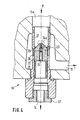
- the power section 10 of the example shown consists of a valve housing 21 in the form of a screw-in cartridge, in which a piston-shaped valve body 22 is movable and rests against an annular valve seat 23 in the closed position.
- the valve body is provided with a bore 24 running in its direction of movement. At the upstream end, the bore is made with a funnel-shaped extension 24 a. Furthermore a flow limiting nozzle 25 is inserted into the bore for calibration.
- the flow opening for the flowing working fluid when opening the valve to the tank return 13 is designated by 26.
- a limit stop 27 at the downstream end of the cartridge 21 serves to limit the stroke of the valve body 22.
- the working fluid flows to the power unit 10 through the end bore of the sleeve-shaped screw-in cartridge 21.
- the bore tapers like a shoulder and forms a peripheral edge 23 which serves as a sealing surface for the valve body 22.
- the valve body touches this sealing edge with its end face, the flow of the working fluid through the screw-in cartridge, ie. H. through the offset sealing bores 26 blocked to the return port 13.
- the inflow of the working fluid is precisely limited by the screw-in nozzle 25, it is matched to the size of the control elements 16 to 20 arranged in the control part 15 and influences the switching speed.
- Control valves 16 to 20 are connected together by the connection 14 power section 10.
- a pressure builds up via the control nozzle behind the valve body 22, which pressure is slightly above that of the inlet. This force moves the valve body against the direction of flow towards the sealing edge 23 and then blocks the flow.
- the back of the valve body receives an area surplus, since the inlet area is reduced by touching the valve body with the sealing edge. The surface excess causes a stable switching position of the valve body in the closed state of the power section.
- the closing force for the closing movement of the valve body 22 is achieved by the configuration of the nozzle inflow 24 a.
- the funnel-shaped or nozzle-shaped inlet stands as a direct inflow surface in the middle of the inlet flow, which is gently deflected into the return annulus 29 outside of the power section due to the conical design of the valve body inflow side when the valve body is open.
- the incoming working fluid is concentrated in the funnel-shaped inlet 24 a of the bore 24 on the flow limiting nozzle 25.
- There is a back pressure which continues through the bore 24 into the space on the rear of the valve body and there increases the pressure beyond the upstream pressure.
- the valve body undergoes a closing movement in the open state, although until the moment of sealing the area of the valve body inflow side is as large as the area on the outflow side and a spring is not used for the resetting.
- the movement force for the valve body adapts itself to the flow conditions. Nevertheless, the use of an additional closing spring is still possible.
Landscapes
- Engineering & Computer Science (AREA)
- Mechanical Engineering (AREA)
- Life Sciences & Earth Sciences (AREA)
- Geology (AREA)
- Mining & Mineral Resources (AREA)
- Fluid-Pressure Circuits (AREA)
- Physics & Mathematics (AREA)
- Environmental & Geological Engineering (AREA)
- Fluid Mechanics (AREA)
- General Life Sciences & Earth Sciences (AREA)
- Geochemistry & Mineralogy (AREA)
Priority Applications (1)
| Application Number | Priority Date | Filing Date | Title |
|---|---|---|---|
| AT83113136T ATE25742T1 (de) | 1983-01-03 | 1983-12-27 | Schalt- und steuereinrichtung fuer hydraulisch oder pneumatisch betaetigbare arbeitsgeraete. |
Applications Claiming Priority (2)
| Application Number | Priority Date | Filing Date | Title |
|---|---|---|---|
| DE3300034A DE3300034C2 (de) | 1983-01-03 | 1983-01-03 | Schalt- und Steuereinrichtung für durch ein Arbeitsfluid antreibbare Arbeitsgeräte |
| DE3300034 | 1983-01-03 |
Publications (3)
| Publication Number | Publication Date |
|---|---|
| EP0115073A2 true EP0115073A2 (fr) | 1984-08-08 |
| EP0115073A3 EP0115073A3 (en) | 1985-05-08 |
| EP0115073B1 EP0115073B1 (fr) | 1987-03-04 |
Family
ID=6187671
Family Applications (1)
| Application Number | Title | Priority Date | Filing Date |
|---|---|---|---|
| EP83113136A Expired EP0115073B1 (fr) | 1983-01-03 | 1983-12-27 | Dispositif d'actionnement et de commande pour appareils hydrauliques ou pneumatiques |
Country Status (3)
| Country | Link |
|---|---|
| EP (1) | EP0115073B1 (fr) |
| AT (1) | ATE25742T1 (fr) |
| DE (1) | DE3300034C2 (fr) |
Cited By (2)
| Publication number | Priority date | Publication date | Assignee | Title |
|---|---|---|---|---|
| AT390124B (de) * | 1985-10-22 | 1990-03-26 | Tampella Oy Ab | Oeffnungsanordnung zum loesen eines aus verschraubten bohrstangen bestehenden bohrgestaenges einer ausruestung fuer langlochbohrung |
| CN113245830A (zh) * | 2021-04-21 | 2021-08-13 | 松阳县古市车木厂 | 一种球阀组装装置 |
Families Citing this family (1)
| Publication number | Priority date | Publication date | Assignee | Title |
|---|---|---|---|---|
| EP0166082B1 (fr) * | 1984-06-28 | 1988-09-07 | Weatherford Oil Tool GmbH | Circuit hydraulique limitant le couple |
Family Cites Families (7)
| Publication number | Priority date | Publication date | Assignee | Title |
|---|---|---|---|---|
| US2780950A (en) * | 1954-09-17 | 1957-02-12 | Phillips Petroleum Co | Hydraulic control system |
| GB1335042A (en) * | 1970-01-05 | 1973-10-24 | Sperry Rand Ltd | Hydraulic actuator controls |
| FR2185087A5 (fr) * | 1972-05-16 | 1973-12-28 | Godines Henri | |
| US4092881A (en) * | 1976-10-29 | 1978-06-06 | Christensen, Inc. | Apparatus for making-up and breaking threaded pipe connections |
| US4280397A (en) * | 1978-04-27 | 1981-07-28 | Joy Manufacturing Company | Hydraulic fluid control apparatus |
| US4170907A (en) * | 1978-05-01 | 1979-10-16 | Joy Manufacturing Company | Door interlock for an open-head power tong |
| US4170908A (en) * | 1978-05-01 | 1979-10-16 | Joy Manufacturing Company | Indexing mechanism for an open-head power tong |
-
1983
- 1983-01-03 DE DE3300034A patent/DE3300034C2/de not_active Expired
- 1983-12-27 EP EP83113136A patent/EP0115073B1/fr not_active Expired
- 1983-12-27 AT AT83113136T patent/ATE25742T1/de not_active IP Right Cessation
Cited By (2)
| Publication number | Priority date | Publication date | Assignee | Title |
|---|---|---|---|---|
| AT390124B (de) * | 1985-10-22 | 1990-03-26 | Tampella Oy Ab | Oeffnungsanordnung zum loesen eines aus verschraubten bohrstangen bestehenden bohrgestaenges einer ausruestung fuer langlochbohrung |
| CN113245830A (zh) * | 2021-04-21 | 2021-08-13 | 松阳县古市车木厂 | 一种球阀组装装置 |
Also Published As
| Publication number | Publication date |
|---|---|
| ATE25742T1 (de) | 1987-03-15 |
| EP0115073A3 (en) | 1985-05-08 |
| EP0115073B1 (fr) | 1987-03-04 |
| DE3300034A1 (de) | 1984-07-05 |
| DE3300034C2 (de) | 1986-09-25 |
Similar Documents
| Publication | Publication Date | Title |
|---|---|---|
| EP1915538B1 (fr) | Montage pour commander un cylindre d'entrainement hydraulique a double effet | |
| DE2547912C3 (de) | Hydraulischer Unterbrecher | |
| EP0934804B1 (fr) | Dispositif à percussion actionné par fluide | |
| EP3058236B1 (fr) | Dispositif de commande | |
| DE60032732T2 (de) | Rohrbruch steuerventil vorrichtung | |
| DE19831595B4 (de) | Hydraulische Schaltung | |
| DE4420459B4 (de) | Vorrichtung zum Steuern eines Hydraulikantriebs | |
| DE2536126C2 (de) | Hydraulisches System | |
| EP0115073B1 (fr) | Dispositif d'actionnement et de commande pour appareils hydrauliques ou pneumatiques | |
| DE10219718B4 (de) | Hydraulische Ventilanordnung | |
| DE2914884C2 (de) | Steuereinrichtung für einen hydraulischen Stempelausbau mit zugeordneter Nachsetzautomatik | |
| EP1629156B1 (fr) | Ensemble commande hydraulique | |
| DE102022126034A1 (de) | Ventilanordnung für Arbeitsmaschinen mit ölhydraulischem Werkzeug | |
| DE60117387T2 (de) | Durchflussbegrenzungsventil | |
| DE2728299A1 (de) | Druckmittelbetriebener antrieb | |
| EP0932783B1 (fr) | Soupape de reduction et de commande | |
| DE2240012A1 (de) | Steuereinrichtung fuer hydrostatische lenkungen u.dgl | |
| DE19715010B4 (de) | Hydraulikgreifer mit Druckbegrenzungsventil | |
| DE102017202899A1 (de) | Regelsystem für eine Hydraulik-Verstellpumpe, Pumpenaggregat und Hydrauliksystem mit einem Pumpenaggregat | |
| DE3844405A1 (de) | Ventilanordnung fuer ein hydraulisches system | |
| DE3139635A1 (de) | Hydraulische steuereinrichtung mit mindestens zwei wegeventilen zur steuerung hydraulischer verbraucher | |
| EP1746015B1 (fr) | Dispositif de direction hydraulique | |
| DE3346184C2 (fr) | ||
| DE2947842C2 (de) | Hydraulische Sicherheitssteuerung mit Druckstufenregelventil | |
| DE2819589C2 (de) | Druckgasbetätigtes Gesteinsbearbeitungsgerät mit Flüssigkeitsspülung |
Legal Events
| Date | Code | Title | Description |
|---|---|---|---|
| PUAI | Public reference made under article 153(3) epc to a published international application that has entered the european phase |
Free format text: ORIGINAL CODE: 0009012 |
|
| 17P | Request for examination filed |
Effective date: 19840114 |
|
| AK | Designated contracting states |
Designated state(s): AT FR GB IT NL SE |
|
| ITCL | It: translation for ep claims filed |
Representative=s name: MODIANO & ASSOCIATI S.R.L. |
|
| EL | Fr: translation of claims filed | ||
| TCNL | Nl: translation of patent claims filed | ||
| PUAL | Search report despatched |
Free format text: ORIGINAL CODE: 0009013 |
|
| AK | Designated contracting states |
Designated state(s): AT FR GB IT NL SE |
|
| 17Q | First examination report despatched |
Effective date: 19860725 |
|
| GRAA | (expected) grant |
Free format text: ORIGINAL CODE: 0009210 |
|
| AK | Designated contracting states |
Kind code of ref document: B1 Designated state(s): AT FR GB IT NL SE |
|
| REF | Corresponds to: |
Ref document number: 25742 Country of ref document: AT Date of ref document: 19870315 Kind code of ref document: T |
|
| ITF | It: translation for a ep patent filed | ||
| ET | Fr: translation filed | ||
| PLBE | No opposition filed within time limit |
Free format text: ORIGINAL CODE: 0009261 |
|
| STAA | Information on the status of an ep patent application or granted ep patent |
Free format text: STATUS: NO OPPOSITION FILED WITHIN TIME LIMIT |
|
| 26N | No opposition filed | ||
| ITTA | It: last paid annual fee | ||
| PGFP | Annual fee paid to national office [announced via postgrant information from national office to epo] |
Ref country code: GB Payment date: 19941208 Year of fee payment: 12 |
|
| PGFP | Annual fee paid to national office [announced via postgrant information from national office to epo] |
Ref country code: FR Payment date: 19941215 Year of fee payment: 12 |
|
| PGFP | Annual fee paid to national office [announced via postgrant information from national office to epo] |
Ref country code: AT Payment date: 19941222 Year of fee payment: 12 |
|
| PGFP | Annual fee paid to national office [announced via postgrant information from national office to epo] |
Ref country code: SE Payment date: 19941223 Year of fee payment: 12 |
|
| PGFP | Annual fee paid to national office [announced via postgrant information from national office to epo] |
Ref country code: NL Payment date: 19941231 Year of fee payment: 12 |
|
| EAL | Se: european patent in force in sweden |
Ref document number: 83113136.2 |
|
| PG25 | Lapsed in a contracting state [announced via postgrant information from national office to epo] |
Ref country code: GB Effective date: 19951227 Ref country code: AT Effective date: 19951227 |
|
| PG25 | Lapsed in a contracting state [announced via postgrant information from national office to epo] |
Ref country code: SE Effective date: 19951228 |
|
| PG25 | Lapsed in a contracting state [announced via postgrant information from national office to epo] |
Ref country code: NL Effective date: 19960701 |
|
| GBPC | Gb: european patent ceased through non-payment of renewal fee |
Effective date: 19951227 |
|
| PG25 | Lapsed in a contracting state [announced via postgrant information from national office to epo] |
Ref country code: FR Effective date: 19960830 |
|
| NLV4 | Nl: lapsed or anulled due to non-payment of the annual fee |
Effective date: 19960701 |
|
| REG | Reference to a national code |
Ref country code: FR Ref legal event code: ST |