EP0115224A2 - Control devices for change speed gearing with rod on sliding ball- and -socket joint - Google Patents
Control devices for change speed gearing with rod on sliding ball- and -socket joint Download PDFInfo
- Publication number
- EP0115224A2 EP0115224A2 EP83402261A EP83402261A EP0115224A2 EP 0115224 A2 EP0115224 A2 EP 0115224A2 EP 83402261 A EP83402261 A EP 83402261A EP 83402261 A EP83402261 A EP 83402261A EP 0115224 A2 EP0115224 A2 EP 0115224A2
- Authority
- EP
- European Patent Office
- Prior art keywords
- rod
- transverse
- lever
- ball joint
- link
- Prior art date
- Legal status (The legal status is an assumption and is not a legal conclusion. Google has not performed a legal analysis and makes no representation as to the accuracy of the status listed.)
- Granted
Links
Images
Classifications
-
- F—MECHANICAL ENGINEERING; LIGHTING; HEATING; WEAPONS; BLASTING
- F16—ENGINEERING ELEMENTS AND UNITS; GENERAL MEASURES FOR PRODUCING AND MAINTAINING EFFECTIVE FUNCTIONING OF MACHINES OR INSTALLATIONS; THERMAL INSULATION IN GENERAL
- F16H—GEARING
- F16H61/00—Control functions within control units of change-speed- or reversing-gearings for conveying rotary motion ; Control of exclusively fluid gearing, friction gearing, gearings with endless flexible members or other particular types of gearing
- F16H61/26—Generation or transmission of movements for final actuating mechanisms
- F16H61/34—Generation or transmission of movements for final actuating mechanisms comprising two mechanisms, one for the preselection movement, and one for the shifting movement
-
- F—MECHANICAL ENGINEERING; LIGHTING; HEATING; WEAPONS; BLASTING
- F16—ENGINEERING ELEMENTS AND UNITS; GENERAL MEASURES FOR PRODUCING AND MAINTAINING EFFECTIVE FUNCTIONING OF MACHINES OR INSTALLATIONS; THERMAL INSULATION IN GENERAL
- F16H—GEARING
- F16H59/00—Control inputs to control units of change-speed- or reversing-gearings for conveying rotary motion
- F16H59/02—Selector apparatus
- F16H59/04—Ratio selector apparatus
- F16H59/042—Ratio selector apparatus comprising a final actuating mechanism
Definitions
- the invention relates to gearbox control devices for motor vehicles, devices comprising an operating lever carried, at a point relatively distant from the gearbox, by a spherical bearing secured to the body of the vehicle, and connected by the same longitudinal rod with two mobile elements of the gearbox.
- the first of these mobile elements is connected by a first link to a substantially vertical selection lever secured to the rod, so that a transverse tilting of the operating lever selects the ratios of the gearbox.
- the second movable element is itself connected by a second link to a lever for returning a vertical axis, a transverse arm of which is connected to the rod by a ball joint, so that a longitudinal tilting of the operating lever achieves the passage of reports.
- the latter is carried on the one hand by the ball joint connecting it to the return lever and, on the other hand, by a transverse axis connecting it to the operating lever so that a transverse tilting thereof causes the rod to pivot about its axis.
- This arrangement has the disadvantage of causing a significant transverse curvature of the longitudinal movements of the lever, during the passage of the reports, because the longitudinal displacements of the rod are accompanied by slight transverse inclinations due to the fact that the ball joint connecting it to the lever , as well as the articulation connecting the selection lever to the first link, describe arcs of a circle, all the more curved as this link, the rod and the transverse arm of the return lever are shorter for the purpose of lightness and compactness of the device.
- the invention aims to reduce this drawback by providing a gearbox control device in which any tilting of the operating lever, during the passage of a gear, takes place in a longitudinal plane, without transverse bending, and which however be simple and space-saving.
- the invention relates to a control device of the aforementioned type, comprising an operating lever carried, at a point relatively distant from the gearbox, by a spherical bearing secured to the body of the vehicle, and connected by a same longitudinal rod with two mobile elements of the gearbox, on each of which is articulated a transverse link, one of these links being attacked by a vertical selection lever secured to the rod, while the other is attacked, to shifting gears, by a vertical axis return lever, a transverse arm of which is connected by a ball joint to the rod, and the rod being further articulated on a third transverse link connecting it to a substantially fixed point of the vehicle and, at its end opposite the connecting rods, on a transverse axis secured to the operating lever.
- the ball joint is movable relative to the rod in a transverse direction substantially parallel to the rods and to the transverse arm of the return lever.
- the ball joint comprises a ball joint fixed on the transverse arm of the return lever, and an externally cylindrical seat mounted to slide in a transverse bore of the rod.
- This bore is in particular the housing inside a tubular part fixed to the rod, for example by welding.
- the ball joint is arranged in the vicinity of a line joining the centers of the joints connecting the rod to the third link and to the operating lever.
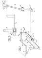
- FIG. 1 shows a device for controlling the gearbox 1 of a vehicle, this device being adapted to successively move two mobile elements, 2, 3 of the gearbox by respective transverse displacements (arrows F1, F ' 1 ) and longitudinal (arrows F 2 , F' 2 ) of an operating lever 4 which is substantially vertical and relatively distant from the gearbox 1.
- the lever 4 is carried by a spherical bearing 5 secured to the body of the vehicle, and is articulated on one end of a longitudinal rod 6 by means of a transverse axis 7 secured to the lever and mounted in a yoke 8 d end of the rod.
- the other end of the rod 6 carries a tubular part 9 with a horizontal transverse axis from which a vertical lever 10, known as the selection lever, leaves, these four parts 6, 8, 9 and 10 being in particular metallic and assembled by welding.
- the tubular part or sleeve 9 and the opposite end of the lever 10 are each fitted with a ball joint 11, 12, on which one of two substantially parallel and horizontal transverse rods, 13, 14, is articulated. substantially equal feeders and respectively connected to the gearbox 1 and the movable element 2.
- a seat 15 externally cylindrical but internally spherical, which cooperates with a ball joint 16 integral with the transverse horizontal arm 17 of a return lever 18.
- the lever 18 also includes a vertical axis 19 which pivots in a bearing 20 fixed to the vehicle body and a longitudinal arm 21 connected to the movable element 3 by a link transverse 22.
- the rod 6 is thus carried on one side by the fixed spherical bearing 5, by means of the lever 4 and the transverse axis 7, and on the other side by the bearing 20, by means of the arm 17 and of the ball joint 16.
- the transverse holding of the rod 6 is ensured at one end by the link 13 and at the other by the lever 4 which is constantly retained substantially in the same radial plane to the rod 6 as the lever 10, by mounting the transverse axis 7 in the yoke 8.
- the ball joint 16 describes a horizontal arc centered on the pivot axis of the return lever 18 and drives its seat 15 which slides in the bore of the tubular part 9 held transversely by the link 13. Consequently, the connection between the arm 17 and the rod 6 does not induce any transverse movement of this rod.
- the selection lever 10 moves with the rod 6 while always remaining parallel to its selected direction, and the ball joints 11 and 12 describe substantially parallel horizontal arcs of the circle since the links 13 and 14 are parallel and of equal or slightly different lengths .
- the translation of the lever 10 is therefore slightly curved.
- the operating lever 4 being in the same radial plane to the rod as the lever 10, also remains parallel to its selected direction and in fact does not undergo any undesirable transverse tilting during the passage of a gear. In other words, the tilting of the lever 4 takes place in a longitudinal plane without transverse curvature.
- the link 13 could, as a variant, connect the rod 6 to a fixed part of the vehicle body.
- the arrangement shown, where this link connects the rod 6 to a part of the gearbox is however preferable in the case where the box 1 is fixed to the body with the interposition of elastic supports allowing slight relative transverse movements between them, because these displacements are accompanied by relative displacements of the tubular piece 9 and of the ball joint 15, 16, without influ ink the chosen position of the other members and in particular of the operating lever.
- the transverse movements of the gearbox cause, via the links 13 and 14, a transverse translation of the lever 10 which, being integral with the sleeve 9, slides with it on the ball joint 15, 16.
- This lever 10 still remains parallel to its selected direction.
- the operating lever 4 in other words, this lever is not subject to untimely transverse movements during the relative movements between the gearbox and the vehicle body.
Landscapes
- Engineering & Computer Science (AREA)
- General Engineering & Computer Science (AREA)
- Mechanical Engineering (AREA)
- Gear-Shifting Mechanisms (AREA)
- Arrangement Or Mounting Of Control Devices For Change-Speed Gearing (AREA)
Abstract
Ce dispositif comporte un levier de manoeuvre (4) relié par une tige unique (6) à deux éléments mobiles (2,3) de la boîte de vitesses, par l'intermédiaire de deux bielles transversales (14,22) attaquées respectivement par un levier de sélection (10) solidaire de la tige et par un levier de renvoi (18) de passage des rapports. Une troisième biellette transversale (13) relie la tige (6) à la boîte elle-même. Le levier de renvoi (18) est relié à la tige par une articulation à rotule montée coulissante dans un manchon (9) fixé transversalement à la tige. Grâce au maintien transversal de la tige (6) par la troisième biellette (13) et au coulissement de l'articulation à rotule dans le manchon (9), le passage des rapports d'effectue par basculement longitudinal du levier sans incurvation transversale intempestive.This device comprises an operating lever (4) connected by a single rod (6) to two mobile elements (2,3) of the gearbox, by means of two transverse connecting rods (14,22) respectively attacked by a selection lever (10) integral with the rod and by a return lever (18) for shifting gears. A third transverse link (13) connects the rod (6) to the box itself. The return lever (18) is connected to the rod by a ball joint slidingly mounted in a sleeve (9) fixed transversely to the rod. Thanks to the transverse holding of the rod (6) by the third link (13) and the sliding of the ball joint in the sleeve (9), the shift of the gear ratios by longitudinal tilting of the lever without inadvertent transverse bending.
Description
L'invention est relative aux dispositifs de commande de boîte de vitesses pour véhicules automobiles, dispositifs comportant un levier de manoeuvre porté, en un point relativement éloigné de la boîte de vitesses, par un palier sphérique solidaire de la caisse du véhicule, et relié par une même tige longitudinale à deux éléments mobiles de la boîte de vitesses. Le premier de ces éléments mobiles est relié par une première biellette à un levier de sélection sensiblement vertical solidaire de la tige, de sorte qu'un basculement transversal du levier de manoeuvre réalise la sélection des rapports de la boîte de vitesses. Le deuxième élément mobile est, lui, relié par une deuxième biellette à un levier de renvoi d'axe vertical, dont un bras transversal est lié à la tige par une articulation à rotule, de sorte qu'un basculement longitudinal du levier de manoeuvre réalise le passage des rapports.The invention relates to gearbox control devices for motor vehicles, devices comprising an operating lever carried, at a point relatively distant from the gearbox, by a spherical bearing secured to the body of the vehicle, and connected by the same longitudinal rod with two mobile elements of the gearbox. The first of these mobile elements is connected by a first link to a substantially vertical selection lever secured to the rod, so that a transverse tilting of the operating lever selects the ratios of the gearbox. The second movable element is itself connected by a second link to a lever for returning a vertical axis, a transverse arm of which is connected to the rod by a ball joint, so that a longitudinal tilting of the operating lever achieves the passage of reports.
Dans une disposition simple ne nécessitant pas de palier de guidage de la tige, celle-ci est portée d'une part par l'articulation à rotule la reliant au levier de renvoi et, d'autre part, par un axe transversal la reliant au levier de manoeuvre de manière qu'un basculement transversal de celui-ci provoque un pivotement de la tige autour de son axe.In a simple arrangement not requiring a bearing for guiding the rod, the latter is carried on the one hand by the ball joint connecting it to the return lever and, on the other hand, by a transverse axis connecting it to the operating lever so that a transverse tilting thereof causes the rod to pivot about its axis.
Cette disposition présente l'inconvénient de provoquer une notable incurvation transversale des mouvements longitudinaux du levier, lors du passage des rapports, car les déplacements longitudinaux de la tige sont accompagnés de légères inclinaisons transversales dues au fait que l'articulation à rotule la reliant au levier de renvoi, de même que l'articulation reliant le levier de sélection à la première biellette, décrivent des arcs de cercle, d'autant plus incurvés que cette biellette, la tige et le bras transversal du levier de renvoi sont plus courts dans un but de légèreté et de faible encombrement du dispositif.This arrangement has the disadvantage of causing a significant transverse curvature of the longitudinal movements of the lever, during the passage of the reports, because the longitudinal displacements of the rod are accompanied by slight transverse inclinations due to the fact that the ball joint connecting it to the lever , as well as the articulation connecting the selection lever to the first link, describe arcs of a circle, all the more curved as this link, the rod and the transverse arm of the return lever are shorter for the purpose of lightness and compactness of the device.
L'invention vise à réduire cet inconvénient en réalisant un dispositif de commande de boîte de vitesses dans lequel tout basculement du levier de manoeuvre, lors du passage d'un rapport, s'effectue dans un plan longitudinal, sans incurvation transversale, et qui cependant soit simple et peu encombrant.The invention aims to reduce this drawback by providing a gearbox control device in which any tilting of the operating lever, during the passage of a gear, takes place in a longitudinal plane, without transverse bending, and which however be simple and space-saving.
Dans ce but l'invention a pour objet un dispositif de commande du type susmentionné, comportant un levier de manoeuvre porté, en un point relativement éloigné de la boîte de vitesses, par un palier sphérique solidaire de la caisse du véhicule, et relié par une même tige longitudinale à deux éléments mobiles de la boîte de vitesses, sur chacun desquels est articulée une biellette transversale, l'une de ces biellettes étant attaquée par un levier de sélection vertical solidaire de la tige, tandis que l'autre est attaquée, pour le passage des rapports, par un levier de renvoi d'axe vertical dont un bras transversal est relié par une articulation à rotule à la tige, et la tige étant en outre articulée sur une troisième biellette transversale la reliant à un point sensiblement fixe du véhicule et, à son extrémité opposée aux biellettes, sur un axe transversal solidaire du levier de manoeuvre. Dans ce dispositif, l'articulation à rotule est mobile par rapport à la tige dans une direction transversale sensiblement parallèle aux biellettes et au bras transversal du levier de renvoi.For this purpose, the invention relates to a control device of the aforementioned type, comprising an operating lever carried, at a point relatively distant from the gearbox, by a spherical bearing secured to the body of the vehicle, and connected by a same longitudinal rod with two mobile elements of the gearbox, on each of which is articulated a transverse link, one of these links being attacked by a vertical selection lever secured to the rod, while the other is attacked, to shifting gears, by a vertical axis return lever, a transverse arm of which is connected by a ball joint to the rod, and the rod being further articulated on a third transverse link connecting it to a substantially fixed point of the vehicle and, at its end opposite the connecting rods, on a transverse axis secured to the operating lever. In this device, the ball joint is movable relative to the rod in a transverse direction substantially parallel to the rods and to the transverse arm of the return lever.
Selon un mode de réalisation préféré, l'articulation à rotule comporte une rotule fixée sur le bras transversal du levier de renvoi, et un siège extérieurement cylindrique monté coulissant dans un alésage transversal de la tige. Cet alésage est notamment le logement intérieur d'une pièce tubulaire fixée à la tige par exemple par soudage.According to a preferred embodiment, the ball joint comprises a ball joint fixed on the transverse arm of the return lever, and an externally cylindrical seat mounted to slide in a transverse bore of the rod. This bore is in particular the housing inside a tubular part fixed to the rod, for example by welding.
L'articulation à rotule est disposée au voisinage d'une ligne joignant les centres des articulations reliant la tige à la troisième biellette et au levier de manoeuvre.The ball joint is arranged in the vicinity of a line joining the centers of the joints connecting the rod to the third link and to the operating lever.
Un exemple de réalisation du dispositif de commande selon l'invention est décrit ci-après, avec référence aux dessins annexés parmi lesquels :
- - la fig. 1 est une vue schématique, en perspective, du dispositif de commande;
- - la fig. 2 est une vue d'une partie du dispositif, en coupe suivant la ligne II-II de la figure 1.
- - fig. 1 is a schematic perspective view of the control device;
- - fig. 2 is a view of part of the device, in section along the line II-II in FIG. 1.
On voit sur la figure 1 un dispositif de commande de la boîte de vitesses 1 d'un véhicule, ce dispositif étant adapté pour déplacer successivement deux éléments mobiles, 2, 3 de la boîte de vitesses par des déplacements respectivement transversaux (flèches F1, F' 1) et longitudinaux (flèches F2, F'2) d'un levier de manoeuvre 4 sensiblement vertical et relativement éloigné de la boîte de vitesses 1.FIG. 1 shows a device for controlling the gearbox 1 of a vehicle, this device being adapted to successively move two mobile elements, 2, 3 of the gearbox by respective transverse displacements (arrows F1, F ' 1 ) and longitudinal (arrows F 2 , F' 2 ) of an
Le levier 4 est porté par un palier sphérique 5 solidaire de la caisse du véhicule, et est articulé sur l'une des extrémités d'une tige longitudinale 6 au moyen d'un axe transversal 7 solidaire du levier et monté dans une chape 8 d'extrémité de la tige. L'autre extrémité de la tige 6 porte une pièce tubulaire 9 d'axe transversal horizontal d'où part un levier vertical 10, dit levier de sélection, ces quatre pièces 6, 8, 9 et 10 étant notamment métalliques et assemblées par soudage. La pièce tubulaire ou manchon 9 et l'extrémité opposée du levier 10 sont équipées chacune d'une rotule 11, 12, sur laquelle s'articule l'une de deux biellettes transversales sensiblement parallèles et horizontales, 13, 14, de longueurs sensiblement égales et respectivement reliées à la boîte de vitesses 1 et à l'élément mobile 2.The
Dans le logement cylindrique interne (9a) de la pièce tubulaire 9 coulisse, au voisinage d'une ligne joignant les centres des articulations 7 et 11, un siège 15 (Fig.2) extérieurement cylindrique mais intérieurement sphérique, qui coopère avec une rotule 16 solidaire du bras horizontal transversal 17 d'un levier de renvoi 18. Le levier 18 comporte également un axe vertical 19 qui pivote dans un palier 20 fixé à la caisse du véhicule et un bras longitudinal 21 relié à l'élément mobile 3 par une biellette transversale 22.In the internal cylindrical housing (9a) of the
La tige 6 est ainsi portée d'un côté par le palier sphérique fixe 5, par l'intermédiaire du levier 4 et de l'axe transversal 7, et de l'autre côté par le palier 20, par l'intermédiaire du bras 17 et de la rotule 16. Le maintien transversal de la tige 6 est assuré à une extrémité par la biellette 13 et à l'autre par le levier 4 qui est constamment retenu sensiblement dans le même plan radial à la tige 6 que le levier 10, par le montage de l'axe transversal 7 dans la chape 8.The
Ainsi, lorsqu'on déplace le levier 4 transversalement (flèches F1, F'1), on provoque la rotation de la tige 6 autour de son axe passant sensiblement par le centre des rotules 11, 15, et le basculement du levier de sélection 10 parallèlement à celui du levier 4, la biellette-13 maintenant transversalement l'extrémité de la tige située à proximité du levier de sélection 10. En basculant, ce levier 10 déplace transversalement la biellette 14 et l'élément mobile 2, réalisant ainsi la sélection d'au moins un rapport.Thus, when the
Le déplacement longitudinal du levier 4 (flèches F2, F'2) provoque ensuite le déplacement longitudinal de la tige 6 et, par l'intermédiaire de l'articulation à rotule 15, 16, le pivotement du levier de renvoi 18 autour de son axe vertical. Le bras 21 de ce levier entraîne transversalement la biellette 22 et l'élément mobile 3,ce qui réalise le passage d'un rapport.The longitudinal displacement of the lever 4 (arrows F 2 , F ' 2 ) then causes the longitudinal displacement of the
Au cours de ce mouvement, la rotule 16 décrit un arc de cercle horizontal centré sur l'axe de pivotement du levier de renvoi 18 et entraîne son siège 15 qui coulisse dans l'alésage de la pièce tubulaire 9 retenue transversalement par la biellette 13. Par suite, la liaison entre le bras 17 et la tige 6 n'induit aucun mouvement transversal de cette tige. Le levier de sélection 10 se déplace avec la tige 6 tout en restant toujours parallèle à sa direction sélectionnée, et les rotules 11 et 12 décrivent des arcs de cercle horizontaux sensiblement parallèles puisque les biellettes 13 et 14 sont parallèles et de longueurs égales ou peu différentes. La translation du levier 10 est donc légèrement incurvée. Toutefois, le levier de manoeuvre 4, étant dans le même plan radial à la tige que le levier 10, reste aussi parallèle à sa direction sélectionnée et ne subit en fait aucun basculement transversal indésirable pendant le passage d'un rapport. Autrement dit, le basculement du levier 4 s'effectue dans un plan longitudinal sans incurvation transversale.During this movement, the
Il est bien évident que la biellette 13 pourrait, en variante, relier la tige 6 à une partie fixe de la caisse du véhicule. La disposition représentée, où cette biellette relie la tige 6 à une partie de la boîte de vitesses, est cependant préférable dans le cas où la boîte 1 est fixée à la caisse avec interposition de supports élastiques autorisant de légers déplacements transversaux relatifs entre elles, car ces déplacements sont accompagnés de déplacements relatifs de la pièce tubulaire 9 et de l'articulation à rotule 15, 16, sans influencer la position choisie des autres organes et notamment du levier de manoeuvre. En effet, les déplacements transversaux de la boîte de vitesses provoquent, par l'intermédiaire des biellettes 13 et 14, une translation transversale du levier 10 qui, étant solidaire du manchon 9, coulisse avec lui sur l'articulation à rotule 15, 16. Ce levier 10 reste encore parallèle à sa direction sélectionnée. Il en est de même du levier de manoeuvre 4; autrement dit, ce levier n'est pas soumis à des mouvements transversaux intempestifs lors des déplacements relatifs entre la boîte de vitesses et la caisse du véhicule.It is obvious that the
Claims (4)
Applications Claiming Priority (2)
| Application Number | Priority Date | Filing Date | Title |
|---|---|---|---|
| FR8219671 | 1982-11-24 | ||
| FR8219671A FR2536554A1 (en) | 1982-11-24 | 1982-11-24 | GEARBOX CONTROL DEVICE WITH ROD ON SLIDING BALL |
Publications (3)
| Publication Number | Publication Date |
|---|---|
| EP0115224A2 true EP0115224A2 (en) | 1984-08-08 |
| EP0115224A3 EP0115224A3 (en) | 1984-08-22 |
| EP0115224B1 EP0115224B1 (en) | 1987-03-18 |
Family
ID=9279469
Family Applications (1)
| Application Number | Title | Priority Date | Filing Date |
|---|---|---|---|
| EP19830402261 Expired EP0115224B1 (en) | 1982-11-24 | 1983-11-23 | Control devices for change speed gearing with rod on sliding ball- and -socket joint |
Country Status (3)
| Country | Link |
|---|---|
| EP (1) | EP0115224B1 (en) |
| DE (1) | DE3370386D1 (en) |
| FR (1) | FR2536554A1 (en) |
Cited By (4)
| Publication number | Priority date | Publication date | Assignee | Title |
|---|---|---|---|---|
| EP0273874A3 (en) * | 1986-02-04 | 1988-07-20 | Fiat Auto S.P.A. | Control device for a motor vehicle gearbox |
| EP0441248A1 (en) * | 1990-02-01 | 1991-08-14 | Iveco Magirus Aktiengesellschaft | Gear shift device for a vehicle |
| EP0448526A1 (en) * | 1990-03-20 | 1991-09-25 | FIAT AUTO S.p.A. | A device for operating a motor-vehicle gearbox |
| CN112428469A (en) * | 2020-11-10 | 2021-03-02 | 谢良育 | Production process of plastic rubber product |
Families Citing this family (4)
| Publication number | Priority date | Publication date | Assignee | Title |
|---|---|---|---|---|
| IT1175789B (en) * | 1984-06-20 | 1987-07-15 | Alfa Romeo Auto Spa | DEVICE FOR THE MANUAL CONTROL OF THE SPEED CHANGE OF A VEHICLE |
| FR2581152B1 (en) * | 1985-04-26 | 1987-07-03 | Renault | MOTION TRANSFORMATION DEVICE FOR INTERNAL GEARBOX CONTROL. |
| FR2696254B1 (en) * | 1992-09-29 | 1994-12-30 | Peugeot | Motor vehicle gear change control linkage. |
| FR2696983B1 (en) * | 1992-10-19 | 1995-01-27 | Peugeot | Motor vehicle gear change control linkage. |
Family Cites Families (6)
| Publication number | Priority date | Publication date | Assignee | Title |
|---|---|---|---|---|
| FR85376E (en) * | 1964-03-02 | 1965-07-30 | Citroen Sa Andre | Remote gearbox control |
| FR1399437A (en) * | 1964-06-25 | 1965-05-14 | Zahnradfabrik Friedrichshafen | Gear shift control device for motor vehicle gearbox |
| FR91733E (en) * | 1966-02-01 | 1968-08-02 | Publicite Francaise | Motor vehicle gearbox control device |
| FR1475771A (en) * | 1966-02-01 | 1967-04-07 | Publicite Francaise | Motor vehicle gearbox control device |
| FR2345306A1 (en) * | 1976-03-26 | 1977-10-21 | Renault | GEARBOX CONTROL DEVICE |
| FR2520134A1 (en) * | 1982-01-18 | 1983-07-22 | Peugeot | DEVICE FOR CONTROLLING A GEARBOX |
-
1982
- 1982-11-24 FR FR8219671A patent/FR2536554A1/en active Granted
-
1983
- 1983-11-23 EP EP19830402261 patent/EP0115224B1/en not_active Expired
- 1983-11-23 DE DE8383402261T patent/DE3370386D1/en not_active Expired
Cited By (4)
| Publication number | Priority date | Publication date | Assignee | Title |
|---|---|---|---|---|
| EP0273874A3 (en) * | 1986-02-04 | 1988-07-20 | Fiat Auto S.P.A. | Control device for a motor vehicle gearbox |
| EP0441248A1 (en) * | 1990-02-01 | 1991-08-14 | Iveco Magirus Aktiengesellschaft | Gear shift device for a vehicle |
| EP0448526A1 (en) * | 1990-03-20 | 1991-09-25 | FIAT AUTO S.p.A. | A device for operating a motor-vehicle gearbox |
| CN112428469A (en) * | 2020-11-10 | 2021-03-02 | 谢良育 | Production process of plastic rubber product |
Also Published As
| Publication number | Publication date |
|---|---|
| FR2536554A1 (en) | 1984-05-25 |
| EP0115224B1 (en) | 1987-03-18 |
| DE3370386D1 (en) | 1987-04-23 |
| EP0115224A3 (en) | 1984-08-22 |
| FR2536554B1 (en) | 1985-03-15 |
Similar Documents
| Publication | Publication Date | Title |
|---|---|---|
| EP0084751B1 (en) | Gear change hand control with locking of the reverse | |
| FR2812612A1 (en) | Bicycle motorized front derailleur gear comprises fork unit for shifting chain and electric motor which controls activating arm through gearing | |
| EP0171318B1 (en) | Device for positioning vehicle head lights | |
| EP0115224B1 (en) | Control devices for change speed gearing with rod on sliding ball- and -socket joint | |
| EP0072464B1 (en) | Manual device for changing gears in a gear box | |
| EP0444994B1 (en) | Adjustable steering column | |
| EP0560645B1 (en) | Speed-change gear box control device, especially for automotive vehicles | |
| EP0084472B1 (en) | Gear-shift device for a gearbox | |
| EP0571274A1 (en) | Parking brake control | |
| EP1538067A1 (en) | Vehicle axle and actuator for said axle | |
| FR2566342A1 (en) | DEVICE FOR MANUAL CONTROL OF THE GEARBOX OF A MOTOR VEHICLE | |
| EP0751322A1 (en) | Vehicle gear selector lever with force sensor | |
| EP0007861B1 (en) | Adjusting device for a rear-view mirror, particularly for a vehicle | |
| FR2732661A1 (en) | Position adjuster for steering column and dashboard of motor vehicle | |
| EP3268636B1 (en) | Device for returning an external control of a gearbox to a neutral position | |
| FR2598127A1 (en) | Device for adjusting the orientation of the reflector of a motor vehicle headlight | |
| FR2696254A1 (en) | Gear selector linkage for gearbox of motor vehicle power unit - uses floating linkage at gearbox end of selector rod in conjunction with two plane linkage on transversely mounted gearbox | |
| FR2863534A1 (en) | Mechanical arm with articulated joint, e.g. for robot or manipulator, has pulley and cable system with driving pulley in plane intersecting that of receiving pulley | |
| FR2503072A1 (en) | Rack operated steering for motor vehicle - has parallel links between rack and steering ball joint | |
| FR2909197A3 (en) | Gear shifting control lever arrangement for passenger compartment of motor vehicle, has intermediate part, whose support device is hooked to inner face of reversed hemispherical cup to plate outer face of cup to contact joint | |
| FR2720365A1 (en) | Automobile front wheel steering assembly | |
| EP0687834B1 (en) | Transmission device with a controlled tensioner | |
| FR2800019A1 (en) | DEVICE FOR CONTROLLING A GEARBOX LOCATED UNDER THE STEERING WHEEL | |
| FR2696983A1 (en) | Automobile vehicle gear change linkage - includes control bar operated by gear change lever, with bar end pivoted to small transversal rod end and other end connected to first gear box lever | |
| FR2884575A1 (en) | Vehicle gearbox gear-changing mechanism has transfer peg connected to control shaft by flexible split ring to provide elasticity |
Legal Events
| Date | Code | Title | Description |
|---|---|---|---|
| PUAI | Public reference made under article 153(3) epc to a published international application that has entered the european phase |
Free format text: ORIGINAL CODE: 0009012 |
|
| PUAL | Search report despatched |
Free format text: ORIGINAL CODE: 0009013 |
|
| AK | Designated contracting states |
Designated state(s): DE GB IT |
|
| AK | Designated contracting states |
Designated state(s): DE GB IT |
|
| 17P | Request for examination filed |
Effective date: 19840712 |
|
| 17Q | First examination report despatched |
Effective date: 19860630 |
|
| ITF | It: translation for a ep patent filed | ||
| GRAA | (expected) grant |
Free format text: ORIGINAL CODE: 0009210 |
|
| AK | Designated contracting states |
Kind code of ref document: B1 Designated state(s): DE GB IT |
|
| REF | Corresponds to: |
Ref document number: 3370386 Country of ref document: DE Date of ref document: 19870423 |
|
| PLBE | No opposition filed within time limit |
Free format text: ORIGINAL CODE: 0009261 |
|
| STAA | Information on the status of an ep patent application or granted ep patent |
Free format text: STATUS: NO OPPOSITION FILED WITHIN TIME LIMIT |
|
| 26N | No opposition filed | ||
| REG | Reference to a national code |
Ref country code: GB Ref legal event code: 746 |
|
| ITPR | It: changes in ownership of a european patent |
Owner name: OFFERTA DI LICENZA AL PUBBLICO |
|
| ITTA | It: last paid annual fee | ||
| PGFP | Annual fee paid to national office [announced via postgrant information from national office to epo] |
Ref country code: DE Payment date: 20011019 Year of fee payment: 19 |
|
| PGFP | Annual fee paid to national office [announced via postgrant information from national office to epo] |
Ref country code: GB Payment date: 20011116 Year of fee payment: 19 |
|
| REG | Reference to a national code |
Ref country code: GB Ref legal event code: IF02 |
|
| PG25 | Lapsed in a contracting state [announced via postgrant information from national office to epo] |
Ref country code: GB Free format text: LAPSE BECAUSE OF NON-PAYMENT OF DUE FEES Effective date: 20021123 |
|
| PG25 | Lapsed in a contracting state [announced via postgrant information from national office to epo] |
Ref country code: DE Free format text: LAPSE BECAUSE OF NON-PAYMENT OF DUE FEES Effective date: 20030603 |
|
| GBPC | Gb: european patent ceased through non-payment of renewal fee |