EP0115232B1 - Dispositif de transmission, notamment pour roue motrice de véhicule automobile, et son procédé de fabrication - Google Patents
Dispositif de transmission, notamment pour roue motrice de véhicule automobile, et son procédé de fabrication Download PDFInfo
- Publication number
- EP0115232B1 EP0115232B1 EP83402470A EP83402470A EP0115232B1 EP 0115232 B1 EP0115232 B1 EP 0115232B1 EP 83402470 A EP83402470 A EP 83402470A EP 83402470 A EP83402470 A EP 83402470A EP 0115232 B1 EP0115232 B1 EP 0115232B1
- Authority
- EP
- European Patent Office
- Prior art keywords
- transmission device
- shaft
- joint
- tubular shaft
- assembly
- Prior art date
- Legal status (The legal status is an assumption and is not a legal conclusion. Google has not performed a legal analysis and makes no representation as to the accuracy of the status listed.)
- Expired
Links
Images

Classifications
-
- B—PERFORMING OPERATIONS; TRANSPORTING
- B60—VEHICLES IN GENERAL
- B60K—ARRANGEMENT OR MOUNTING OF PROPULSION UNITS OR OF TRANSMISSIONS IN VEHICLES; ARRANGEMENT OR MOUNTING OF PLURAL DIVERSE PRIME-MOVERS IN VEHICLES; AUXILIARY DRIVES FOR VEHICLES; INSTRUMENTATION OR DASHBOARDS FOR VEHICLES; ARRANGEMENTS IN CONNECTION WITH COOLING, AIR INTAKE, GAS EXHAUST OR FUEL SUPPLY OF PROPULSION UNITS IN VEHICLES
- B60K17/00—Arrangement or mounting of transmissions in vehicles
- B60K17/22—Arrangement or mounting of transmissions in vehicles characterised by arrangement, location, or type of main drive shafting, e.g. cardan shaft
-
- F—MECHANICAL ENGINEERING; LIGHTING; HEATING; WEAPONS; BLASTING
- F16—ENGINEERING ELEMENTS AND UNITS; GENERAL MEASURES FOR PRODUCING AND MAINTAINING EFFECTIVE FUNCTIONING OF MACHINES OR INSTALLATIONS; THERMAL INSULATION IN GENERAL
- F16C—SHAFTS; FLEXIBLE SHAFTS; ELEMENTS OR CRANKSHAFT MECHANISMS; ROTARY BODIES OTHER THAN GEARING ELEMENTS; BEARINGS
- F16C3/00—Shafts; Axles; Cranks; Eccentrics
- F16C3/02—Shafts; Axles
-
- F—MECHANICAL ENGINEERING; LIGHTING; HEATING; WEAPONS; BLASTING
- F16—ENGINEERING ELEMENTS AND UNITS; GENERAL MEASURES FOR PRODUCING AND MAINTAINING EFFECTIVE FUNCTIONING OF MACHINES OR INSTALLATIONS; THERMAL INSULATION IN GENERAL
- F16D—COUPLINGS FOR TRANSMITTING ROTATION; CLUTCHES; BRAKES
- F16D1/00—Couplings for rigidly connecting two coaxial shafts or other movable machine elements
- F16D1/06—Couplings for rigidly connecting two coaxial shafts or other movable machine elements for attachment of a member on a shaft or on a shaft-end
-
- F—MECHANICAL ENGINEERING; LIGHTING; HEATING; WEAPONS; BLASTING
- F16—ENGINEERING ELEMENTS AND UNITS; GENERAL MEASURES FOR PRODUCING AND MAINTAINING EFFECTIVE FUNCTIONING OF MACHINES OR INSTALLATIONS; THERMAL INSULATION IN GENERAL
- F16D—COUPLINGS FOR TRANSMITTING ROTATION; CLUTCHES; BRAKES
- F16D3/00—Yielding couplings, i.e. with means permitting movement between the connected parts during the drive
- F16D3/16—Universal joints in which flexibility is produced by means of pivots or sliding or rolling connecting parts
- F16D3/20—Universal joints in which flexibility is produced by means of pivots or sliding or rolling connecting parts one coupling part entering a sleeve of the other coupling part and connected thereto by sliding or rolling members
- F16D3/202—Universal joints in which flexibility is produced by means of pivots or sliding or rolling connecting parts one coupling part entering a sleeve of the other coupling part and connected thereto by sliding or rolling members one coupling part having radially projecting pins, e.g. tripod joints
- F16D3/205—Universal joints in which flexibility is produced by means of pivots or sliding or rolling connecting parts one coupling part entering a sleeve of the other coupling part and connected thereto by sliding or rolling members one coupling part having radially projecting pins, e.g. tripod joints the pins extending radially outwardly from the coupling part
- F16D3/2055—Universal joints in which flexibility is produced by means of pivots or sliding or rolling connecting parts one coupling part entering a sleeve of the other coupling part and connected thereto by sliding or rolling members one coupling part having radially projecting pins, e.g. tripod joints the pins extending radially outwardly from the coupling part having three pins, i.e. true tripod joints
-
- F—MECHANICAL ENGINEERING; LIGHTING; HEATING; WEAPONS; BLASTING
- F16—ENGINEERING ELEMENTS AND UNITS; GENERAL MEASURES FOR PRODUCING AND MAINTAINING EFFECTIVE FUNCTIONING OF MACHINES OR INSTALLATIONS; THERMAL INSULATION IN GENERAL
- F16D—COUPLINGS FOR TRANSMITTING ROTATION; CLUTCHES; BRAKES
- F16D3/00—Yielding couplings, i.e. with means permitting movement between the connected parts during the drive
- F16D3/16—Universal joints in which flexibility is produced by means of pivots or sliding or rolling connecting parts
- F16D3/20—Universal joints in which flexibility is produced by means of pivots or sliding or rolling connecting parts one coupling part entering a sleeve of the other coupling part and connected thereto by sliding or rolling members
- F16D3/202—Universal joints in which flexibility is produced by means of pivots or sliding or rolling connecting parts one coupling part entering a sleeve of the other coupling part and connected thereto by sliding or rolling members one coupling part having radially projecting pins, e.g. tripod joints
- F16D3/207—Universal joints in which flexibility is produced by means of pivots or sliding or rolling connecting parts one coupling part entering a sleeve of the other coupling part and connected thereto by sliding or rolling members one coupling part having radially projecting pins, e.g. tripod joints the pins extending radially inwardly from the coupling part
Definitions
- the present invention relates to a transmission device between a motor unit and a drive wheel, in a motor vehicle, of the type comprising two constant velocity joints connected by a tubular intermediate shaft, this shaft being welded at at least one of its ends to an element of the adjacent joint which delimits raceways and which is made of a steel with high characteristics having undergone a thermo-chemical treatment giving it a high surface hardness.
- the drive shaft carries at at least one of its ends a constant velocity joint element delimiting raceways for rollers or balls, which raceways therefore have to withstand contact pressures or Hertz pressure of high value of the order of 400 kg / mnT 'for example.
- this element of the joint is therefore subjected before its mounting on the transmission shaft to a thermochemical treatment intended to give it the desired characteristics of surface hardness.
- the aim of this invention is to produce a transmission of the type defined at the head of this document which is, with equal resistance characteristics, lighter than known transmissions and more effective with regard to the elimination of vibrations.
- tubular shaft also made of steel with high characteristics for thermochemical treatment is welded to said element before thermochemical treatment of the latter, the assembly formed by the shaft and the element having undergone the same after assembly
- thermochemical cementation or carbonitriding treatment followed by quenching, giving it a high surface hardness.
- the subject of the invention is also a method of manufacturing such a device, characterized in that a tubular shaft and at least one constant velocity joint element, assembled in the same grade with high characteristics for thermochemical treatment, are assembled by welding, or in neighboring grades, then the assembly is subjected to a thermochemical treatment of carburizing or carbonitriding, followed by quenching, giving it a high surface hardness.
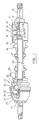
- FIG. 1 is a view in longitudinal section of a transmission device according to the invention.
- Figs. 2 to 7 are partial sectional views of alternative modes of connection between the ends of the shaft and the elements of the adjacent constant velocity joints.
- a transmission device in particular for the lateral transmission of a motor vehicle, comprising two constant velocity joints 10, 20 connected by a transmission shaft 30.
- the first seal 10, of the sliding type comprises a tulip 11 secured to a shaft section 12 intended to be driven from the power unit and a tripod 13 carrying three journals 14 arranged at 120 ° on which are rotatably mounted and sliding rollers 15 of spherical shape received in rectilinear tracks 16 provided in the tulip.
- the spider comprises a hub provided at its inner periphery with splines or serrations 13 b engaged with corresponding splines or serrations 17b of an end piece 17 fixed by welding to the adjacent end of the connecting shaft.
- the end piece comprises on its face directed towards the shaft 30 an annular skirt 17a whose diameter and wall thickness correspond to those of the tube which constitutes the shaft 30.
- the second joint 20 also constant velocity is a fixed tripod joint comprising a bowl 21 intended to be connected to the hub (not shown) of the wheel to be driven, this bowl being integral with a tripod 22 on the three pins 23 of which are arranged spherical rollers 24 received in the raceways 25 delimited by a tulip 26.
- Means known per se and comprising in particular an elastic fastener 27 are provided to make this joint fixed that is ie without the possibility of axial movement between the tripod and the tulip.
- the tulip 26 ends at its end directed towards the connecting shaft by a skirt 26a whose diameter and wall thickness correspond to those of the shaft 30.
- the assembly is completed, in a conventional manner by sealing bellows 18 and 28.
- the material constituting the tubular connecting shaft 30 is a steel for thermochemical treatment and preferably steel identical or close to that which constitutes the end piece 17 and the tulip 26. It is a steel with high characteristics, for example a chromium molybdenum steel of type 25 or 27 CD4, the tensile strength of which can be of the order of 300 kg / mm 2 and which after treatment offers a Rockwell C hardness equal to or greater than 62.
- the assembly by welding of the tube 30 and its two end elements: end piece 17 and tulip 26, is carried out before the heat treatment operation which the tulip must undergo and it is the welded assembly consisting of the shaft 30, the end piece 17 and the tulip 26 which is subjected to this thermochemical treatment, for example, a cementation or carbonitriding operation followed by quenching, such treatment being known per se and n therefore not having to be described in detail.
- thermochemical treatment for example, a cementation or carbonitriding operation followed by quenching, such treatment being known per se and n therefore not having to be described in detail.
- the welds themselves can be made by friction, electron bombardment or any other suitable method.
- tubular shaft 30 delimits with the two elements 17, 26 to which it is fixed a closed cavity 31, so that during the thermochemical treatment, the treatment gas does not penetrate into this cavity and does not affect not the metal inside the tube. This characteristic is all the more important as the thickness of the tube 30 is smaller, for example less than 1.5 mm.
- the weight gain obtained by using a connecting tube is of the order of 0.7 kg for a total weight of the connection assembly consisting of the tube and its two end elements, of the order of 2.4 kg, which is considerable.
- a tube 130 is used with a larger diameter and a smaller thickness, for example less than or equal to 1.5 mm, this configuration possibly being made necessary by the operating characteristics of the transmission.
- the connection between the tube and the adjacent element can then be made, either by means of a constriction 131 of the tube (FIG. 2) or by means of a bloom 126 8 produced in the last forming operation at cold on said adjacent element, in this case the tulip 126 of the fixed joint (Fig. 3).
- the splined end piece 217 receiving the tripod 213 of the sliding joint may have come integrally with the tubular element 230 (Fig. 4).
- the tubular element 230 Fig. 4
- either the corresponding end of the tube is closed or else it is almost closed, that is to say only delimits a passage 231 of small cross section and relatively large length to prevent circulation of the gas of treatment.
- each of the two ends of the shaft is closed by an element active of the adjacent constant velocity joint, comprising rolling surfaces which must offer high surface hardness.
- Fig. 6 shows a variant derived from that of FIG. 5, in which the shaft section 401 secured to the tripod 402 delimits in its diameter part reduces a groove 403 for fixing the neck of a sealing bellows (not shown).
- the shaft 401 also has an open end 404, welded to the shaft 405.
- FIG. 7 shows another variant, in which a tripod 501 is welded to one end 502 of reduced diameter of the hollow shaft 503, the latter delimiting in this same part of reduced diameter, a groove 504 for fixing the neck of the sealing bellows .
- This arrangement is particularly favorable for good fixing of the bellows and easy clearance of the joint.
Landscapes
- Engineering & Computer Science (AREA)
- General Engineering & Computer Science (AREA)
- Mechanical Engineering (AREA)
- Chemical & Material Sciences (AREA)
- Combustion & Propulsion (AREA)
- Transportation (AREA)
- Ocean & Marine Engineering (AREA)
- Shafts, Cranks, Connecting Bars, And Related Bearings (AREA)
- Solid-Phase Diffusion Into Metallic Material Surfaces (AREA)
- Arrangement And Driving Of Transmission Devices (AREA)
- Motor Power Transmission Devices (AREA)
- Heat Treatment Of Articles (AREA)
Description
- La présente invention concerne un dispositif de transmission entre un groupe moteur et une roue motrice, dans un véhicule automobile, du type comprenant deux joints homocinétiques reliés par un arbre intermédiaire tubulaire, cet arbre étant soudé à au moins une de ses extrémités à un élément du joint adjacent qui délimite des chemins de roulement et qui est réalisé en un acier à hautes caractéristiques ayant subi un traitement thermo-chimique lui conférant une dureté superficielle élevée.
- Un tel agencement est décrit dans le document FR-A-2 429 928.
- On connaît de plus d'après le brevet FR-A-2 345 522 un agencement dans lequel un arbre de transmission tubulaire est soudé à son extrémité sur une mâchoire de joint de cardan. Cet ensemble soudé est ensuite soumis à un traitement thermique consistant en un chauffage, suivi d'une trempe et d'un revenu, qui a pour but d'améliorer les caractéristiques de résistance structurelle de la pièce et d'éliminer les contraintes résiduelles résultant du soudage.
- Un ensemble ainsi traité ne convient pas dans l'application particulière envisagée où l'arbre de transmission porte à au moins une de ses extrémités un élément de joint homocinétique délimitant des chemins de roulement pour des galets ou des billes, lesquels chemins de roulement ont donc à supporter des pressions de contact ou pression de Hertz de valeur élevée de l'ordre de 400 kg/mnT' par exemple. Habituellement, cet élément du joint est donc soumis avant son montage sur l'arbre de transmission à un traitement thermochimique destiné à lui donner les caractéristiques souhaitées de dureté superficielle.
- On sait par ailleurs que ce type de traitement peut, dans certaines conditions, avoir un effet négatif sur la tenue et la résistance mécanique des pièces qui y sont soumises et l'on a même été conduit pour pallier cet inconvénient à prévoir des réserves, c'est-à-dire à masquer certaines parties de ces pièces pour leur éviter d'entrer en contact avec le gaz de traitement.
- C'est ainsi que le document US-A-4 279 528 décrit une tulipe de joint homocinétique tripode comprenant des pétales et un tronçon d'arbre, les réserves précitées étant prévues dans les zones de liaison entre les pétales et le tronçon d'arbre adjacent.
- Le but poursuivi par cette invention est de réaliser une transmission du type défini en tête de ce document qui soit, à caractéristiques égales de résistance, plus légère que les transmissions connues et plus efficaces vis-à-vis de l'élimination des vibrations.
- Elle a donc pour objet un tel dispositif de transmission, caractérisé en ce que l'arbre tubulaire réalisé également en acier à hautes caractéristiques pour traitement thermochimique est soudé audit élément avant traitement thermochimique de ce dernier, l'ensemble formé par l'arbre et l'élément ayant subi après assemblage le même
- traitement thermochimique de cémentation ou de carbonitruration, suivi d'une trempe, lui conférant une dureté superficielle élevée.
- Suivant d'autres caractéristiques:
- - l'arbre tubulaire et le ou chaque élément de joint auquel il est soudé délimitent une cavité fermée;
- - l'arbre tubulaire et le ou chaque élément de joint auquel il est soudé délimitent une cavité quasi fermée;
- - l'élément du joint comporte une jupe sur laquelle est soudée l'extrémité adjacente de l'arbre intermédiaire;
- - cette jupe a un diamètre et une épaisseur de paroi correspondant à ceux de l'extrémité adjacente de l'arbre tubulaire;
- --l'arbre comporte un rétreint à au moins une de ses extrémités;
- - la jupe comporte une partie épanouie.
- L'invention a également pour objet un procédé de fabrication d'un tel dispositif, caractérisé en ce qu'on assemble par soudure un arbre tubulaire et au moins un élément de joint homocinétique, réalisés dans une même nuance à hautes caractéristiques pour traitement thermochimique, ou dans des nuances voisines, puis on soumet l'ensemble à un traitement thermochimique de cémentation ou de carbonitruration, suivi d'une trempe, lui conférant une dureté superficielle élevée.
- L'invention sera mieux comprise à l'aide de la description qui va suivre, donnée uniquement à titre d'exemple et faite en se référant aux dessins annexés, sur lesquels:
- - la Fig. 1 est une vue en coupe longitudinale d'un dispositif de transmission suivant l'invention;
- -les Fig. 2 à 7 sont des vues partielles en coupe de variantes de modes de liaison entre les extrémités de l'arbre et les éléments des joints homocinétiques adjacents.
- On voit sur la Fig. 1 un dispositif de transmission, en particulier pour transmission latérale de véhicule automobile, comprenant deux joints homocinétiques 10, 20 reliés par un arbre de transmission 30.
- Le premier joint 10, de type coulissant comprend une tulipe 11 solidaire d'un tronçon d'arbre 12 destiné à être entraîné à partir du groupe moteur et un tripode 13 portant trois tourillons 14 disposés à 120° sur lesquels sont montés rotatifs et coulissants des galets 15 de forme sphérique reçus dans des pistes rectilignes 16 prévues dans la tulipe. Dans cette réalisation, le tripode comporte un moyeu muni à sa périphérie interne de cannelures ou dentelures 13b en prise sur des dentelures ou cannelures correspondantes 17b d'un embout 17 fixé par soudure sur l'extrémité adjacente de l'arbre de liaison. A cet effet, l'embout comporte sur sa face dirigée vers l'arbre 30 une jupe annulaire 17a dont le diamètre et l'épaisseur de paroi correspondent à ceux du tube qui constitue l'arbre 30.
- Le deuxième joint 20 également homocinétique est un joint fixe à tripode comprenant un bol 21 destiné à être relié au moyeu (non représenté) de la roue à entraîner, ce bol étant solidaire d'un tripode 22 sur les trois tourillons 23 duquel sont disposés des galets sphériques 24 reçus dans les chemins de roulement 25 délimités par une tulipe 26. Des moyens connus en soi et comportant notamment une attache élastique 27 sont prévus pour rendre ce joint fixe c'est-à-dire sans possibilité de débattement axial entre le tripode et la tulipe. La tulipe 26 se termine à son extrémité dirigée vers l'arbre de liaison par une jupe 26a dont le diamètre et l'épaisseur de paroi correspondent à ceux de l'arbre 30.
- L'ensemble est complété, de façon classique par des soufflets d'étanchéité 18 et 28.
- Suivant l'invention, le matériau constituant l'arbre tubulaire de liaison 30 est un acier pour traitement thermochimique et de préférence en acier identique ou voisin de celui qui constitue l'embout 17 et la tulipe 26. Il s'agit d'un acier à caractéristiques élevées, par exemple un acier au chrome molybdène de type 25 ou 27 CD4 dont la résistance à la traction peut être de l'ordre de 300 kg/mm2 et qui après traitement offre une dureté Rockwell C égale ou supérieure à 62.
- Suivant l'invention également, l'assemblage par soudure du tube 30 et de ses deux éléments d'extrémité: embout 17 et tulipe 26, est réalisé avant l'opération de traitementthermique que doit subir la tulipe et c'est l'ensemble soudé constitué de l'arbre 30, de l'embout 17 et de la tulipe 26 qui est soumis à ce traitement thermochimique, par exemple, une opération de cémentation ou de carbonitruration suivie d'une trempe, un tel traitement étant en soi connu et n'ayant pas par conséquent à être décrit en détail.
- Les soudures elles-mêmes peuvent être réalisées par friction, bombardement électronique ou tout autre procédé convenable.
- Il est important de noter que l'arbre tubulaire 30 délimite avec les deux éléments 17, 26 auxquels il est fixé une cavité fermée 31, de sorte que lors du traitement thermochimique, le gaz de traitement ne pénètre pas dans cette cavité et n'affecte pas le métal à l'intérieur du tube. Cette caractéristique est d'autant plus importante que l'épaisseur du tube 30 est plus faible, par exemple inférieure à 1,5 mm.
- Le dispositif et le procédé que l'on vient de décrire offrent un faisceau d'avantages très importants par rapport aux diverses solutions connues et contrairement à ce que l'on aurait pu craindre, le traitement de cémentation ou de carbonitruration n'a pas de conséquences néfastes sur la résistance structurelle de l'ensemble ni sur la tenue.
- Utilisant un acier à hautes caractéristiques, on peut prévoir un tube de faible diamètre extérieur (27 mm par exemple) et de faible épaisseur (3 ou 3,5 mm) qui est néanmoins capable de transmettre le couple qui peuvent supporter les joints (de l'ordre de 300 m.daN dans l'exemple considéré).
- Par rapport à une solution classique (barre de 24 mm de diamètre ou tube serti 35-27 mm, ces deux dimensions représentent respectivement les diamètres externe et interne du tube), le gain de poids procuré en utilisant un tube de liaison (27-20 mm) est de l'ordre de 0,7 kg pour un poids total de l'ensemble de liaison constitué du tube et de ses deux éléments d'extrémité, de l'ordre de 2,4 kg, ce qui est considérable.
- Les essais effectués tant au banc que sur véhicule montrent que le comportement dynamique d'une transmission ainsi réalisée est excellent et l'on note en particulier une amélioration très sensible au niveau de l'élimination des diverses vibrations engendrées par le groupe moteur.
- Dans la variante de la Fig. 2, on a représenté le cas où l'on utilise un tube 130 de plus gros diamètre et d'épaisseur plus faible par exemple irtfé- rieure ou égale à 1,5 mm, cette configuration pouvant être rendue nécessaire par les caractéristiques de fonctionnement de la transmission. La liaison entre le tube et l'élément adjacent peut alors se faire, soit par l'intermédiaire d'un rétreint 131 du tube (Fig. 2) soit par l'intermédiaire d'un épanouissement 1268 réalisé en dernière opération de formage à froid sur ledit élément adjacent, en l'occurrence la tulipe 126 du joint fixe (Fig. 3).
- Suivant une autre variante, l'embout cannelé 217 recevant le tripode 213 du joint coulissant, peut être venu de matière avec l'élément tubulaire 230 (Fig. 4). Dans ce cas, ou bien l'extrémité correspondante du tube est fermée ou bien elle est quasiment fermée, c'est-à-dire ne délimite qu'un passage 231 de faible section et de longueur relativement importante pour empêcher une circulation du gaz de traitement.
- On peut également réaliser comme représenté sur la Fig. 5 une liaison directe par soudure du tripode 313 du joint coulissant sur l'arbre tubulaire 330 dont l'extrémité est, le cas échéant, épanouie, en 331. Dans ce cas, chacune des deux extrémités de l'arbre est fermée par un élément actif du joint homocinétique adjacent, comportant des surfaces de roulement devant offrir une haute dureté superficielle.
- La Fig. 6 représente une variante dérivée de celle de la Fig. 5, dans laquelle le tronçon d'arbre 401 solidaire du tripode 402 délimite dans sa partie de diamètre réduit une gorge 403 de fixation du goulot d'un soufflet d'étanchéité (non représenté). L'arbre 401 comporte par ailleurs une extrémité 404 épanouie, soudée sur l'arbre 405.
- Enfin, la Fig. 7 représente une autre variante, dans laquelle un tripode 501 est soudé sur une extrémité 502 de diamètre réduit de l'arbre creux 503, ce dernier délimitant dans cette même partie de diamètre réduit, une gorge 504 de fixation du goulot du soufflet d'étanchéité. Cette disposition est particulièrement favorable pour une bonne fixation du soufflet et un débattement aisé du joint.
Claims (13)
Applications Claiming Priority (2)
| Application Number | Priority Date | Filing Date | Title |
|---|---|---|---|
| FR8221773A FR2538476B1 (fr) | 1982-12-24 | 1982-12-24 | Dispositif de transmission, notamment pour roue motrice de vehicule automobile, et son procede de fabrication |
| FR8221773 | 1982-12-24 |
Publications (2)
| Publication Number | Publication Date |
|---|---|
| EP0115232A1 EP0115232A1 (fr) | 1984-08-08 |
| EP0115232B1 true EP0115232B1 (fr) | 1989-09-06 |
Family
ID=9280507
Family Applications (1)
| Application Number | Title | Priority Date | Filing Date |
|---|---|---|---|
| EP83402470A Expired EP0115232B1 (fr) | 1982-12-24 | 1983-12-19 | Dispositif de transmission, notamment pour roue motrice de véhicule automobile, et son procédé de fabrication |
Country Status (6)
| Country | Link |
|---|---|
| US (1) | US4698046A (fr) |
| EP (1) | EP0115232B1 (fr) |
| JP (1) | JPS59137219A (fr) |
| DE (1) | DE3380526D1 (fr) |
| ES (1) | ES528300A0 (fr) |
| FR (1) | FR2538476B1 (fr) |
Families Citing this family (10)
| Publication number | Priority date | Publication date | Assignee | Title |
|---|---|---|---|---|
| JPS62197230A (ja) * | 1986-02-25 | 1987-08-31 | Fuji Tool & Die Co Ltd | 車両用連結ロツドの製造方法 |
| GB2217670B (en) * | 1988-03-17 | 1991-12-11 | Honda Motor Co Ltd | A method and apparatus for assembling a vehicular driving shaft |
| FR2633350B1 (fr) * | 1988-06-22 | 1993-02-05 | Glaenzer Spicer Sa | Agencement d'un capot de protection sur la tulipe d'un joint de transmission |
| US5509495A (en) * | 1991-01-30 | 1996-04-23 | Dr. Ing. H.C.F. Porsche Ag | Drive assembly for motor vehicles |
| DE4137988C1 (fr) * | 1991-11-19 | 1992-12-17 | Gkn Automotive Ag, 5200 Siegburg, De | |
| US5951401A (en) * | 1996-12-31 | 1999-09-14 | Honda Giken Kogyo Kabushiki Kaisha | Slave driving force-transmitting mechanism for vehicle |
| BE1015486A3 (fr) | 1999-09-30 | 2005-05-03 | Honda Motor Co Ltd | Appareil et procede pour serrer une bande de fixation et appareil a joint universel a vitesse constante. |
| US20050137022A1 (en) * | 2003-12-19 | 2005-06-23 | Neeley Donald E. | Apparatus and method for friction welded tripod interconnecting shaft |
| KR102174259B1 (ko) * | 2018-09-28 | 2020-11-04 | 일진제강(주) | 업세팅 공법을 이용한 중공 드라이브 샤프트 및 이의 제조 방법 |
| EP4421339B1 (fr) * | 2023-02-27 | 2026-04-22 | CP Tech GmbH | Arbre d'entraînement avec étoile tripode intégrale |
Family Cites Families (17)
| Publication number | Priority date | Publication date | Assignee | Title |
|---|---|---|---|---|
| GB147860A (en) * | 1916-02-10 | 1921-10-10 | Victor Lee Emerson | Improvements in universal coupling members and method of producing the same |
| US1508897A (en) * | 1921-06-10 | 1924-09-16 | Gen Motors Corp | Torque-tube connection |
| US2003508A (en) * | 1930-08-04 | 1935-06-04 | Jencick Stephen | Propeller shaft |
| US2898749A (en) * | 1957-10-18 | 1959-08-11 | William C Parkman | Universal joint adjusting means |
| US2952999A (en) * | 1958-07-02 | 1960-09-20 | Gen Motors Corp | Shaft connections |
| IL35806A (en) * | 1969-12-11 | 1973-07-30 | Gkn Birfield Transmissions Ltd | Universal joints |
| US4068499A (en) * | 1976-01-26 | 1978-01-17 | Sharp Everett H | Telescoping universal joints |
| MX4399E (es) * | 1976-03-26 | 1982-04-23 | Dana Corp | Metodo mejorado para fabricar un conjunto de flecha impulsora de peso liviano |
| GB1585164A (en) * | 1976-06-24 | 1981-02-25 | Gkn Transmissions Ltd | Universal joint and shaft assemblies |
| DE2652386A1 (de) * | 1976-11-15 | 1978-07-27 | Mannesmann Ag | Verfahren zum haerten eines zahnrades |
| US4173501A (en) * | 1978-06-01 | 1979-11-06 | Clark Equipment Company | Steel torsional element and method for making |
| FR2429928A1 (fr) * | 1978-06-29 | 1980-01-25 | Glaenzer Spicer Sa | Transmission, notamment pour vehicule a traction avant |
| FR2436282A1 (fr) * | 1978-09-18 | 1980-04-11 | Glaenzer Spicer Sa | Tulipe perfectionnee pour joint a tripode et procede pour sa fabrication |
| FR2444194A1 (fr) * | 1978-12-14 | 1980-07-11 | Glaenzer Spicer Sa | Joint coulissant a tripode perfectionne et transmission comprenant deux tels joints |
| DE2950787C2 (de) * | 1979-12-17 | 1986-10-16 | Bergische Stahl-Industrie, 5630 Remscheid | Scheibenbremse für Schienenfahrzeuge |
| FR2496798B1 (fr) * | 1980-12-19 | 1986-03-21 | Glaenzer Spicer Sa | Joint homocinetique de transmission, notamment pour roue motrice de vehicule a traction avant |
| FR2502270A1 (fr) * | 1981-03-19 | 1982-09-24 | Renault | Element de joint homocinetique du type tripode |
-
1982
- 1982-12-24 FR FR8221773A patent/FR2538476B1/fr not_active Expired
-
1983
- 1983-12-19 DE DE8383402470T patent/DE3380526D1/de not_active Expired
- 1983-12-19 EP EP83402470A patent/EP0115232B1/fr not_active Expired
- 1983-12-22 ES ES528300A patent/ES528300A0/es active Granted
- 1983-12-24 JP JP58252402A patent/JPS59137219A/ja active Granted
-
1985
- 1985-12-09 US US06/805,585 patent/US4698046A/en not_active Expired - Lifetime
Also Published As
| Publication number | Publication date |
|---|---|
| ES8406658A1 (es) | 1984-08-01 |
| EP0115232A1 (fr) | 1984-08-08 |
| US4698046A (en) | 1987-10-06 |
| JPH0362568B2 (fr) | 1991-09-26 |
| JPS59137219A (ja) | 1984-08-07 |
| FR2538476B1 (fr) | 1987-08-21 |
| ES528300A0 (es) | 1984-08-01 |
| DE3380526D1 (en) | 1989-10-12 |
| FR2538476A1 (fr) | 1984-06-29 |
Similar Documents
| Publication | Publication Date | Title |
|---|---|---|
| FR2579695A1 (fr) | Arbre de transmission | |
| FR2691769A1 (fr) | Joint homocinétique à billes et son procédé de fabrication. | |
| FR2478236A1 (fr) | Dispositif d'etancheite pour joint d'articulation, notamment pour joint de transmission d'un arbre de roue de vehicule automobile | |
| EP0115232A1 (fr) | Dispositif de transmission, notamment pour roue motrice de véhicule automobile, et son procédé de fabrication | |
| FR2728816A1 (fr) | Procede pour former un element d'arbre et de fourchette monobloc a partir d'un flan de tubage ayant une section transversale generalement circulaire | |
| FR2489754A1 (fr) | Ensemble de moyeu de roue pour vehicule automobile | |
| FR2651182A1 (fr) | Arbre d'essieu pouvant supporter un couple eleve. | |
| FR2619878A1 (fr) | Procede de fabrication d'un assemblage entre une bague interieure metallique et un tube en une matiere plastique armee de fibres, ainsi qu'un assemblage realise selon ce procede | |
| FR2711407A1 (fr) | Perfectionnements aux barres de torsion métalliques. | |
| FR2686132A1 (fr) | Joint homocinetique tournant a billes. | |
| FR2732427A1 (fr) | Appareil d'accouplement hydrocinetique, notamment pour vehicule automobile | |
| EP0122853B1 (fr) | Axe de volant pour colonne de direction de véhicule automobile | |
| FR3052104A1 (fr) | Assemblage de roue motrice de vehicule automobile | |
| FR2560948A1 (fr) | Procede de fabrication de chemins de roulement de billes et organe muni d'un chemin de roulement | |
| FR2562969A1 (fr) | Dispositif de liaison coulissante a cannelures et application de ce dispositif a un embrayage | |
| FR2686660A1 (fr) | Procede de fixation d'une garniture d'etancheite sur un boitier cylindrique et procede de fixation d'une garniture d'etancheite sur un boitier de joint de transmission et sur un arbre. | |
| FR2499910A1 (fr) | Moyeu de roue entraine par un joint homocinetique | |
| EP0239427A1 (fr) | Joint de transmission homocinétique pour véhicules automobiles | |
| CH620380A5 (fr) | ||
| EP0732518A2 (fr) | Joint homocinétique à rotule centrale | |
| BE1022119B1 (fr) | Arbre de transmission et son procede de fabrication | |
| FR2947218A1 (fr) | Assemblage de transmission de vehicule automobile, notamment ferroviaire | |
| FR2524110A1 (fr) | Procede de fabrication d'un tube avec des conduits disposes dans sa paroi | |
| FR2566858A1 (fr) | Joint homocinetique a tres libre coulissement, notamment pour vehicule automobile | |
| EP0061368A1 (fr) | Elément de joint homocinétique du type tripode |
Legal Events
| Date | Code | Title | Description |
|---|---|---|---|
| PUAI | Public reference made under article 153(3) epc to a published international application that has entered the european phase |
Free format text: ORIGINAL CODE: 0009012 |
|
| AK | Designated contracting states |
Designated state(s): DE FR GB IT |
|
| 17P | Request for examination filed |
Effective date: 19850126 |
|
| 17Q | First examination report despatched |
Effective date: 19860127 |
|
| GRAA | (expected) grant |
Free format text: ORIGINAL CODE: 0009210 |
|
| AK | Designated contracting states |
Kind code of ref document: B1 Designated state(s): DE FR GB IT |
|
| ITF | It: translation for a ep patent filed | ||
| GBT | Gb: translation of ep patent filed (gb section 77(6)(a)/1977) | ||
| REF | Corresponds to: |
Ref document number: 3380526 Country of ref document: DE Date of ref document: 19891012 |
|
| PLBE | No opposition filed within time limit |
Free format text: ORIGINAL CODE: 0009261 |
|
| STAA | Information on the status of an ep patent application or granted ep patent |
Free format text: STATUS: NO OPPOSITION FILED WITHIN TIME LIMIT |
|
| 26N | No opposition filed | ||
| ITTA | It: last paid annual fee | ||
| PGFP | Annual fee paid to national office [announced via postgrant information from national office to epo] |
Ref country code: DE Payment date: 19931122 Year of fee payment: 11 |
|
| PGFP | Annual fee paid to national office [announced via postgrant information from national office to epo] |
Ref country code: GB Payment date: 19931214 Year of fee payment: 11 |
|
| PG25 | Lapsed in a contracting state [announced via postgrant information from national office to epo] |
Ref country code: GB Effective date: 19941219 |
|
| GBPC | Gb: european patent ceased through non-payment of renewal fee |
Effective date: 19941219 |
|
| PG25 | Lapsed in a contracting state [announced via postgrant information from national office to epo] |
Ref country code: DE Effective date: 19950901 |
|
| PGFP | Annual fee paid to national office [announced via postgrant information from national office to epo] |
Ref country code: FR Payment date: 19981228 Year of fee payment: 16 |
|
| PG25 | Lapsed in a contracting state [announced via postgrant information from national office to epo] |
Ref country code: FR Free format text: LAPSE BECAUSE OF NON-PAYMENT OF DUE FEES Effective date: 20000831 |
|
| REG | Reference to a national code |
Ref country code: FR Ref legal event code: ST |