EP0115363A2 - Procédé et appareil pour le traitement d'articles vulnérables ainsi qu'un récipient adapté à l'application du procédé - Google Patents
Procédé et appareil pour le traitement d'articles vulnérables ainsi qu'un récipient adapté à l'application du procédé Download PDFInfo
- Publication number
- EP0115363A2 EP0115363A2 EP84200074A EP84200074A EP0115363A2 EP 0115363 A2 EP0115363 A2 EP 0115363A2 EP 84200074 A EP84200074 A EP 84200074A EP 84200074 A EP84200074 A EP 84200074A EP 0115363 A2 EP0115363 A2 EP 0115363A2
- Authority
- EP
- European Patent Office
- Prior art keywords
- belt
- containers
- container
- conveyor
- conveyor belt
- Prior art date
- Legal status (The legal status is an assumption and is not a legal conclusion. Google has not performed a legal analysis and makes no representation as to the accuracy of the status listed.)
- Granted
Links
Images




Classifications
-
- B—PERFORMING OPERATIONS; TRANSPORTING
- B65—CONVEYING; PACKING; STORING; HANDLING THIN OR FILAMENTARY MATERIAL
- B65B—MACHINES, APPARATUS OR DEVICES FOR, OR METHODS OF, PACKAGING ARTICLES OR MATERIALS; UNPACKING
- B65B23/00—Packaging fragile or shock-sensitive articles other than bottles; Unpacking eggs
- B65B23/02—Packaging or unpacking eggs
- B65B23/06—Arranging, feeding, or orientating the eggs to be packed; Removing eggs from trays or cartons
-
- A—HUMAN NECESSITIES
- A01—AGRICULTURE; FORESTRY; ANIMAL HUSBANDRY; HUNTING; TRAPPING; FISHING
- A01K—ANIMAL HUSBANDRY; AVICULTURE; APICULTURE; PISCICULTURE; FISHING; REARING OR BREEDING ANIMALS, NOT OTHERWISE PROVIDED FOR; NEW BREEDS OF ANIMALS
- A01K43/00—Testing, sorting or cleaning eggs ; Conveying devices ; Pick-up devices
-
- B—PERFORMING OPERATIONS; TRANSPORTING
- B65—CONVEYING; PACKING; STORING; HANDLING THIN OR FILAMENTARY MATERIAL
- B65G—TRANSPORT OR STORAGE DEVICES, e.g. CONVEYORS FOR LOADING OR TIPPING, SHOP CONVEYOR SYSTEMS OR PNEUMATIC TUBE CONVEYORS
- B65G2201/00—Indexing codes relating to handling devices, e.g. conveyors, characterised by the type of product or load being conveyed or handled
- B65G2201/02—Articles
- B65G2201/0235—Containers
- B65G2201/0261—Puck as article support
Definitions
- the invention relates to a method of transporting articles along successive stations and handling the same therein, e.g. arranging candling, weighing, encoding, grading and the like of vulnerable products, such as eggs.
- US patent 4,086,998 of Applicants discloses a method and apparatus for grading eggs, in which the eggs supplied on trays are transferred onto a weighing apparatus, then onto a conveyor belt, from which the eggs are transferred to buffer belts disposed along the conveyer belt, at the exit of which buffer belts the eggs are arranged according to a given pattern and are again transferred therefrom to a tray or the like carrier member (see also US patent 3,973,667 of Applicants).
- nine transfers take place, starting from the suplly until the putting of the graded egg into the tray or box, namely:
- each article at the beginning of the handling cycle, is separately received in a container that is freely movable in at least one direction during a part of the handling cycle, and is removed therefrom after the handling cycle.
- the number of transfers may be restricted, if desired, to two, i.e. from the tray wherein the eggs are supplied to the said container and after handling the article, from the container to a box or tray.
- Each container supplied, at the weighing -station, is first weighed in empty condition.and, after the reception of a product therein, together therewith, thus determining the weight and the weight class of.the article.
- the invention further relates to a container adapted to be applied in the above described method, which container is open at the top, narrowing towards the bottom, e.g. according to one or more truncated cones, and further comprising a foot extending perpendicularly to the container axis, the outer circumference of said foot being at least equal to the outer circumference of the upper edge of the container.
- the invention also relates to an apparatus for transporting vulnerable products such as eggs, along successive stations and handling the same therein, said apparatus comprising a plurality of conveyor members over at least some of which the articles are relatively freely movable in at least one direction, said apparatus being characterized in that freely movable containers are arranged on said conveyor members over which the articles are freely movable, for separately conveying the articles.
- the invention further relates to a grading device comprising a feed belt, as well as a plurality of buffer belts arranged therealong, said apparatus being characterized in that the feed belt is fitted with gripping or carrying members for receiving the containers or eggs, while along the feed belt, at each of the buffer belts, there are arranged one or more expelling or releasing mechanisms for expelling or releasing the containers or eggs from the gripping or carrying members.
- a bottom plate is arranged directly above the lower run of the buffer belt for transporting the empty containers, which bottom plate is magnetic, just as the return roller of said buffer belt disposed at the discharge end, each of the containers being provided with a part made of sort iron or other magnetizable material.
- a bottom plate which is made of soft iron, just as the return roller of the buffer belt disposed at the discharge end of said buffer belt, the containers being provided with a magnet, so that the containers are carried along "hanging" from the lower run of the buffer belt.
- two conveyor belts extending underneath the buffer belts may be provided for returning the containers from the buffer belts, one of these extending in the same direction as the feed belt, at which location the said bottom plates terminate, so that the containers hanging from the buffer belts are transferred onto said conveyor belt.
- a second conveyor belt may be arranged with extends in opposite direction, and adjacent the lastmentioned buffer belt there may be provided a transfer apparatus above the said first and second conveyor belt.
- Said transfer apparatus may consist of a bottom plate which is extended relative to the other bottom plates.
- an inserting station for pushing the empty containers in the feed belt.
- Said inserting station may consist of a plurality of baffles arranged longitudinally above the conveyor belt and of a plurality of baffles arranged downstream thereof, transversely to the transport direction above the conveyor belt, each having a different length, while furthermore a plurality of inserting members are arranged at the end of said conveyor belt opposite the feed belt, adjacent the baffles disposed transversely to the transport direction.
- a chute and a mill and wing arranged there-above may be provided at the transfer location.
- each guide plate when a plurality of guide plates are arranged above the discharge end of each buffer belt, each guide plate may be mounted on a hinged bracket, and be provided at a downstream end with a blocking member for containers, and be tiltable by means of a magnet or the like, so that the containers can pass.
- the invention also relates to an apparatus for grading vulnerable articles, such as eggs, said apparatus comprising a weighing station and being characterized in that adjacent the end of the second conveyor belt there is provided an inserting station for placing the containers successively on a third conveyor belt, along which third conveyor belt there are arranged expelling members for transferring each container successively to a first scale or weighing cell disposed underneath a chute or the like, subsequently to a second scale or cell, and finally to the feed belt.
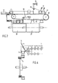
- an apparatus for transporting articles along successive stations and handling the same therein comprises an orienting roller conveyor 1, on which eggs 2 are oriented: the left half of the eggs supplied with the small end to the right and the right half of the eggs supplied with the small end to the left.
- Apparatus for orienting eggs are known per se from e.g. US patents 2,895,589 and 3,024.889.
- the eggs are transferred via a chute 3 and a mill wing 4 to containers 5 received in a feed belt 6.
- each container comprises a double frusto-conical body 7 having a broad foot 8.
- the frusto-conical body has a maximal diameter defined by a circular-cylindrical ring 9, which is equal to the diameter of the foot 8.
- an annular magnet 10 is received in the foot of the container.
- the links of the feed belt 6 are fitted with grippers 11: the grippers 11 are designed in such a manner that they can snappingly engage the containers at the portion just above the foot.
- the feed belt After the filling of all containers present opposite the orienting roller conveyor during standstill of the feed belt, the feed belt is moved a distance corresponding with the number of containers just filled, so that again a corresponding number of empty containers is brought in the filling positions.
- the feed belt 6 is driven intermittently via a shaft 12 and a sprocket wheel 13.
- a plurality of buffer belts 14, 15 and 16, three in the embodiment shown, are arranged along the feed belt 6.
- the respective containers On arrival of the containers filled with weighed eggs at the buffer belt associated with the egg weight class in question, the respective containers are transferred during the standstill of the feed belt or chain 6 onto the buffer belt 14, 15 or 16 in question by means of an expelling mechanism 17, 18 or 19.
- each expelling mechanism 17, 18 or 19 is provided with some (in the present case six) cylinders corresponding with the number of containers per pitch of the intermittently driven feed belt, the free piston rod end of which is adapted to push the containers 5 out of the grippers 11 when the cylinders are operated.
- a filled container is to be emptied, i.e. the egg received in the container pertains to the respective weigh class, is determined by a known per se control means of a microprocessor, not shown, which has received the weighing data immediately after weighing, from the weighing members, not shown in Figs. 1-3.
- the eggs with suckers are taken from the containers and discharged (in Fig. 2 shown by arrows 21).
- the said pattern is obtained partly in that the baffles are provided at the downstream end with a cam 22 by measn of which the filled containers supplied are retained.
- the passage of the containers takes place in such a manner that the baffles 20 are hinged to a shaft 23, and a projection of the baffle is adapted to be operated by a magnet 24.
- a bottom plate 25 of a given length there is provided above the lower run of the buffer belts a bottom plate 25 of a given length.
- Both the said bottom plate and the return roller 26 disposed at the respective end of the buffer belt in the embodiment shown are made of soft iron, so that the container adjacent the said return roller and bottom plate continues to "adhere" to the moving buffer belt.
- the containers will get detached from the buffer belt and fall on a conveyor belt 27 disposed at a small distance thereunder, moving in the same direction as the feed belt 6.
- a second conveyor belt 28 extending in a sense opposite to that of the conveyor belt 27.
- the bottom plate 25 Adjacent the last mentioned buffer belt, seen in the direction of movement of the feed belt 6, the bottom plate 25 extends along a larger distance than is the case with all buffer belts arranged in front thereof along the feed belt. As a result, the said bottom plate together with the associated buffer belt functions as transfer mechanism. For the containers supplied via the conveyor belt 27 will stick to the same buffer belt 16 and, together with the containers already sticking thereto, will be moved in the direction of movement of the buffer belt. Since the bottom plate in question terminates all the second conveyor belt 28, the containers at that location will get detached from the buffer belt and fall on the second conveyor belt 28. The conveyor belt 28 returns the containers 5 naturally still upside down to the "inlet end", where an inserting station 29 is arranged.
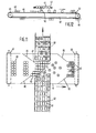
- Said inserting station comprises a plurality of baffles 30 disposed above the conveyor belt 28 and extending in the transport direction, as well as a plurality of baffles 31 arranged upstream thereof, transversely to the transport direction, each of the lastmentioned baffles having a different length. Furthermore, there are provided at the end of the said conveyor belt 28 opposite the feed belt 6, adjacent the baffles 31 arranged transversely to the transport direction, a plurality of inserting members 32, which are basically identical to the expelling mechanisms 17, 18 and 19. The number of inserting members 32 corresponds, in the same manner as the expelling mechanisms 17, 18 and 19, to the number of containers per pitch.
- the arrangement chosen makes it possible to receive the required number of containers at a large speed in the gripping members 11 of the feed chain 6. Moreover, due to this construction with two conveyor belts, i.e. 27 and 28, all containers essentially traverse the same distance, thus preventing obstruction in the system, which would be the case though when the containers should be returned to the inserting station immediately after discharge of the eggs therefrom.
- the empty containers supplied by the conveyor belt 28 are not pushed in the feed belt 6, but on a third conveyor belt 34 suitable only for one row of containers. Beside the upper run of the conveyor belt 34, there are arranged a number of scales or weighing cells 35 corresponding to the number of containers per pitch, and which are disposed underneath the chutes 3. As shown in particular in Figs. 6 and 7, the empty containers supplied via the conveyor belt 33 are pushed from the conveyor belt 34 on the scales 35 by means of an expelling mechanism 36, comparable to the expelling mechanisms 17, 18 and 19. After weighing the empty containers, an egg supplied via the orienting roller conveyor 1 slides therein.
- the containers meanwhile filled with eggs are shifted and moved on a second scale or cell 37, allowing to accurately determine the weight of the egg in question.
- the weighed egg-filled container is pressed in the gripper 11 of the conveyor belt 6, after which the egg-filled containers are further handled in the manner as described in the above with reference to Figs. 1 - 4 and 8 - 10.
- Figs. 11 and 12 relating to a different embodiment of the buffer belt and the feed conveyor belt, show a buffer belt 41 with thereabove a feed conveyor belt 42, with rotatably arranged forkshaped containers 90 (details are described and shown in Dutch patent application 8202980 and also US patent application (number unknown)) and with eggs 43 of different dimensions disposed thereon.
- the buffer belt comprises a conveyor belt 44 and return rollers 45.
- Above the buffer belt (Fig. 11) there are arranged at the left of the feed belt 42 guide plates 46 blending with a narrowing 47. Adjacent the narrowing, there are arranged a plurality of guide plates (omitted for the sake of clarity), which are adapted for coaction with egg cups or containers49 disposed thereon for free movement relative to the buffer belt.
- the number of tracks formed adjacent the narrowing 47 corresponds with the number of tracks of the egg feed belt 42 (in this case six).
- Above the buffer belt there are arranged detainers 50 extending in the tracks formed by the guide plates.
- the detainers 50 can be operated by magnets, not shown.
- a guide plate 55 and a passage, not shown, fitted with detainers 57 Arranged above the discharge end of the buffer belt 41, in succession, are a guide plate 55 and a passage, not shown, fitted with detainers 57.
- the detainers can be operated in the same manner as the detainers 50 by magnets, not shown.
- Figs. 13 and 14 relating again to a different embodiment of a buffer belt with a superimposed feed conveyor belt, the same parts are indicated by the same reference numerals as used in Figs.. 11 and 12.
- the differences reside in that the feed conveyor belt 42 extends and moves in the same direction as the subjacent buffer belt 41, above which there are disposed guide plates, not shown, directed oppositely to the guide plates 46 in Fig. 11.
- the transfer of the eggs to the cups 49 takes place by means of a mill (turnstile) 70 and a subjacent chute 71, according to the embodiment shown in Fig. 4.
- a third and last difference consists in that the sidewalls 55 of the buffer belt are movable; for details thereof, reference is made to applicants' US patent 4,086,998.
- a transfer apparatus 72 fitted with bellows.
Landscapes
- Life Sciences & Earth Sciences (AREA)
- Environmental Sciences (AREA)
- Engineering & Computer Science (AREA)
- Mechanical Engineering (AREA)
- Animal Husbandry (AREA)
- Biodiversity & Conservation Biology (AREA)
- Wrapping Of Specific Fragile Articles (AREA)
- Specific Conveyance Elements (AREA)
- Feeding Of Articles To Conveyors (AREA)
Applications Claiming Priority (2)
| Application Number | Priority Date | Filing Date | Title |
|---|---|---|---|
| NL8300287A NL8300287A (nl) | 1982-07-23 | 1983-01-26 | Werkwijze en inrichting voor het behandelen van kwetsbare voorwerpen alsmede houder ingericht voor toepassing bij deze werkwijze. |
| NL8300287 | 1983-01-26 |
Publications (3)
| Publication Number | Publication Date |
|---|---|
| EP0115363A2 true EP0115363A2 (fr) | 1984-08-08 |
| EP0115363A3 EP0115363A3 (en) | 1984-08-22 |
| EP0115363B1 EP0115363B1 (fr) | 1987-04-22 |
Family
ID=19841291
Family Applications (1)
| Application Number | Title | Priority Date | Filing Date |
|---|---|---|---|
| EP19840200074 Expired EP0115363B1 (fr) | 1983-01-26 | 1984-01-20 | Procédé et appareil pour le traitement d'articles vulnérables ainsi qu'un récipient adapté à l'application du procédé |
Country Status (3)
| Country | Link |
|---|---|
| EP (1) | EP0115363B1 (fr) |
| JP (1) | JPS59167404A (fr) |
| DE (1) | DE3463212D1 (fr) |
Cited By (3)
| Publication number | Priority date | Publication date | Assignee | Title |
|---|---|---|---|---|
| EP0390241A3 (fr) * | 1989-03-10 | 1990-12-19 | Terpa Poultry B.V. | Procédé et appareil pour arrêter temporairement un convoyeur entraíné, pourvu de moyens de support et guidé sur des rouleaux à entraínement réciproques |
| WO2012097813A1 (fr) * | 2011-01-19 | 2012-07-26 | Sanovo Technology A/S | Procédé et appareil pour transférer des œufs à partir de casiers à œufs vers un appareil de traitement d'œufs |
| CN118807571A (zh) * | 2024-09-19 | 2024-10-22 | 秦皇岛三农现代化机械设备有限公司 | 一种智能配料混合包装设备 |
Families Citing this family (2)
| Publication number | Priority date | Publication date | Assignee | Title |
|---|---|---|---|---|
| JPS62194507U (fr) * | 1986-05-29 | 1987-12-10 | ||
| JPS62194508U (fr) * | 1986-05-29 | 1987-12-10 |
Family Cites Families (4)
| Publication number | Priority date | Publication date | Assignee | Title |
|---|---|---|---|---|
| NL6512101A (fr) * | 1965-09-16 | 1967-03-17 | ||
| JPS44381Y1 (fr) * | 1965-12-25 | 1969-01-09 | ||
| DE1761636B2 (de) * | 1968-06-19 | 1975-02-13 | Kuhl, Henry Y., Flemington, N.Y. (V.St.A.) | Vorrichtung zum Ausrichten von Eiern |
| JPS56123215A (en) * | 1980-02-22 | 1981-09-28 | Hiroshi Tomosue | Feeder for egg in egg treating machine |
-
1984
- 1984-01-20 DE DE8484200074T patent/DE3463212D1/de not_active Expired
- 1984-01-20 EP EP19840200074 patent/EP0115363B1/fr not_active Expired
- 1984-01-23 JP JP992484A patent/JPS59167404A/ja active Pending
Cited By (3)
| Publication number | Priority date | Publication date | Assignee | Title |
|---|---|---|---|---|
| EP0390241A3 (fr) * | 1989-03-10 | 1990-12-19 | Terpa Poultry B.V. | Procédé et appareil pour arrêter temporairement un convoyeur entraíné, pourvu de moyens de support et guidé sur des rouleaux à entraínement réciproques |
| WO2012097813A1 (fr) * | 2011-01-19 | 2012-07-26 | Sanovo Technology A/S | Procédé et appareil pour transférer des œufs à partir de casiers à œufs vers un appareil de traitement d'œufs |
| CN118807571A (zh) * | 2024-09-19 | 2024-10-22 | 秦皇岛三农现代化机械设备有限公司 | 一种智能配料混合包装设备 |
Also Published As
| Publication number | Publication date |
|---|---|
| EP0115363B1 (fr) | 1987-04-22 |
| JPS59167404A (ja) | 1984-09-20 |
| EP0115363A3 (en) | 1984-08-22 |
| DE3463212D1 (en) | 1987-05-27 |
Similar Documents
| Publication | Publication Date | Title |
|---|---|---|
| US4627215A (en) | Apparatus for charging receptacles with stacked, flat items | |
| AU698435B2 (en) | A method and a system for building up weighed-out portions of objects | |
| US6834755B2 (en) | Conveying machines | |
| EP0098733B2 (fr) | Système de traitement des oeufs | |
| US4955794A (en) | Apparatus for forming and conveying groups of flat stacked items | |
| NL8900584A (nl) | Werkwijze en inrichting voor het tijdelijk stilzetten van een over omkeerwielen geleide, aangedreven transporteur met houders. | |
| EP1201542B1 (fr) | Machine pour trier et emballer des produits agricols/animals et méthode de commande de ladite machine | |
| WO2008058069A9 (fr) | Appareil permettant de séparer et de transporter des articles | |
| US4708250A (en) | Method and an apparatus for handling vulnerable articles, as well as a container adapted to apply this method | |
| EP0115363A2 (fr) | Procédé et appareil pour le traitement d'articles vulnérables ainsi qu'un récipient adapté à l'application du procédé | |
| US6711877B2 (en) | Food product handling machine | |
| US4356920A (en) | Method and apparatus for grading and further processing eggs | |
| EP0803716B1 (fr) | Dispositif pour peser dynamiquement des fruits | |
| JPS61287622A (ja) | 自動洗卵選別装置における卵の移し替え装置 | |
| US4645062A (en) | Transfer apparatus for flat items | |
| US4848479A (en) | Straight line checkweigher | |
| US6786322B2 (en) | Cooling tunnel for flexible packages filled with hot liquid products | |
| US5918445A (en) | Automatic packaging machine for inserting a few small items with desired orientation into a carton | |
| WO2002044670A1 (fr) | Procede et appareil pour peser des objets suspendus | |
| EP0074827B1 (fr) | Dispositif combinatoire de pesage | |
| EP0489478A1 (fr) | Appareil pour placer des objets sur un convoyeur | |
| EP0564670B1 (fr) | Système de remplissage | |
| JPH09150941A (ja) | 鶏卵の移替え装置 | |
| JP3617863B2 (ja) | 組合せ秤 | |
| JPH0334304Y2 (fr) |
Legal Events
| Date | Code | Title | Description |
|---|---|---|---|
| PUAI | Public reference made under article 153(3) epc to a published international application that has entered the european phase |
Free format text: ORIGINAL CODE: 0009012 |
|
| PUAL | Search report despatched |
Free format text: ORIGINAL CODE: 0009013 |
|
| AK | Designated contracting states |
Designated state(s): DE FR GB IT NL |
|
| AK | Designated contracting states |
Designated state(s): DE FR GB IT NL |
|
| 17P | Request for examination filed |
Effective date: 19840910 |
|
| GRAA | (expected) grant |
Free format text: ORIGINAL CODE: 0009210 |
|
| AK | Designated contracting states |
Kind code of ref document: B1 Designated state(s): DE FR GB IT NL |
|
| PG25 | Lapsed in a contracting state [announced via postgrant information from national office to epo] |
Ref country code: IT Free format text: LAPSE BECAUSE OF FAILURE TO SUBMIT A TRANSLATION OF THE DESCRIPTION OR TO PAY THE FEE WITHIN THE PRESCRIBED TIME-LIMIT;WARNING: LAPSES OF ITALIAN PATENTS WITH EFFECTIVE DATE BEFORE 2007 MAY HAVE OCCURRED AT ANY TIME BEFORE 2007. THE CORRECT EFFECTIVE DATE MAY BE DIFFERENT FROM THE ONE RECORDED. Effective date: 19870422 Ref country code: FR Free format text: THE PATENT HAS BEEN ANNULLED BY A DECISION OF A NATIONAL AUTHORITY Effective date: 19870422 |
|
| REF | Corresponds to: |
Ref document number: 3463212 Country of ref document: DE Date of ref document: 19870527 |
|
| EN | Fr: translation not filed | ||
| PLBE | No opposition filed within time limit |
Free format text: ORIGINAL CODE: 0009261 |
|
| STAA | Information on the status of an ep patent application or granted ep patent |
Free format text: STATUS: NO OPPOSITION FILED WITHIN TIME LIMIT |
|
| 26N | No opposition filed | ||
| REG | Reference to a national code |
Ref country code: GB Ref legal event code: 746 |
|
| PGFP | Annual fee paid to national office [announced via postgrant information from national office to epo] |
Ref country code: GB Payment date: 19920221 Year of fee payment: 9 |
|
| PGFP | Annual fee paid to national office [announced via postgrant information from national office to epo] |
Ref country code: DE Payment date: 19920324 Year of fee payment: 9 |
|
| PG25 | Lapsed in a contracting state [announced via postgrant information from national office to epo] |
Ref country code: GB Effective date: 19930120 |
|
| GBPC | Gb: european patent ceased through non-payment of renewal fee |
Effective date: 19930120 |
|
| PG25 | Lapsed in a contracting state [announced via postgrant information from national office to epo] |
Ref country code: DE Effective date: 19931001 |
|
| NLS | Nl: assignments of ep-patents |
Owner name: HAWE ELEKTROTRAKTIE B.V. TE BERGSCHENHOEK. |
|
| PGFP | Annual fee paid to national office [announced via postgrant information from national office to epo] |
Ref country code: NL Payment date: 19970131 Year of fee payment: 14 |
|
| PG25 | Lapsed in a contracting state [announced via postgrant information from national office to epo] |
Ref country code: NL Free format text: LAPSE BECAUSE OF NON-PAYMENT OF DUE FEES Effective date: 19980801 |
|
| NLV4 | Nl: lapsed or anulled due to non-payment of the annual fee |
Effective date: 19980801 |