EP0115423A1 - Fülleinheit zum Auffüllen eines Behälters mit Flüssigkeit - Google Patents
Fülleinheit zum Auffüllen eines Behälters mit Flüssigkeit Download PDFInfo
- Publication number
- EP0115423A1 EP0115423A1 EP84300424A EP84300424A EP0115423A1 EP 0115423 A1 EP0115423 A1 EP 0115423A1 EP 84300424 A EP84300424 A EP 84300424A EP 84300424 A EP84300424 A EP 84300424A EP 0115423 A1 EP0115423 A1 EP 0115423A1
- Authority
- EP
- European Patent Office
- Prior art keywords
- vessel
- liquid
- container
- orifice
- downpipe
- Prior art date
- Legal status (The legal status is an assumption and is not a legal conclusion. Google has not performed a legal analysis and makes no representation as to the accuracy of the status listed.)
- Granted
Links
- 239000007788 liquid Substances 0.000 title claims abstract description 98
- 239000000945 filler Substances 0.000 title claims abstract description 31
- 239000007789 gas Substances 0.000 claims description 14
- 230000001105 regulatory effect Effects 0.000 claims description 10
- 238000009833 condensation Methods 0.000 claims description 5
- 230000005494 condensation Effects 0.000 claims description 5
- 230000005484 gravity Effects 0.000 claims description 5
- 239000000463 material Substances 0.000 claims description 5
- 230000003068 static effect Effects 0.000 claims description 4
- 239000000835 fiber Substances 0.000 claims description 2
- 238000012856 packing Methods 0.000 claims description 2
- 230000000694 effects Effects 0.000 description 6
- XLYOFNOQVPJJNP-UHFFFAOYSA-N water Chemical compound O XLYOFNOQVPJJNP-UHFFFAOYSA-N 0.000 description 5
- 238000010276 construction Methods 0.000 description 4
- 230000006835 compression Effects 0.000 description 3
- 238000007906 compression Methods 0.000 description 3
- 230000014759 maintenance of location Effects 0.000 description 3
- 230000000630 rising effect Effects 0.000 description 3
- 239000000126 substance Substances 0.000 description 3
- 238000009736 wetting Methods 0.000 description 3
- 239000002826 coolant Substances 0.000 description 2
- 230000003247 decreasing effect Effects 0.000 description 2
- 239000003792 electrolyte Substances 0.000 description 2
- 238000001704 evaporation Methods 0.000 description 2
- 230000008020 evaporation Effects 0.000 description 2
- 238000000034 method Methods 0.000 description 2
- 230000004048 modification Effects 0.000 description 2
- 238000012986 modification Methods 0.000 description 2
- 239000008213 purified water Substances 0.000 description 2
- 238000009825 accumulation Methods 0.000 description 1
- 239000002253 acid Substances 0.000 description 1
- 230000009286 beneficial effect Effects 0.000 description 1
- 230000033228 biological regulation Effects 0.000 description 1
- 239000000919 ceramic Substances 0.000 description 1
- 230000000295 complement effect Effects 0.000 description 1
- 230000001276 controlling effect Effects 0.000 description 1
- 238000001816 cooling Methods 0.000 description 1
- 230000001351 cycling effect Effects 0.000 description 1
- 238000005868 electrolysis reaction Methods 0.000 description 1
- 238000004880 explosion Methods 0.000 description 1
- 239000002360 explosive Substances 0.000 description 1
- 238000007667 floating Methods 0.000 description 1
- 238000012423 maintenance Methods 0.000 description 1
- 230000013011 mating Effects 0.000 description 1
- 239000003595 mist Substances 0.000 description 1
- 239000000203 mixture Substances 0.000 description 1
- 239000012466 permeate Substances 0.000 description 1
- 230000000644 propagated effect Effects 0.000 description 1
- 238000005086 pumping Methods 0.000 description 1
- 238000004064 recycling Methods 0.000 description 1
- 238000007789 sealing Methods 0.000 description 1
- 239000007779 soft material Substances 0.000 description 1
- 239000007921 spray Substances 0.000 description 1
- 239000002699 waste material Substances 0.000 description 1
Images


Classifications
-
- H—ELECTRICITY
- H01—ELECTRIC ELEMENTS
- H01M—PROCESSES OR MEANS, e.g. BATTERIES, FOR THE DIRECT CONVERSION OF CHEMICAL ENERGY INTO ELECTRICAL ENERGY
- H01M50/00—Constructional details or processes of manufacture of the non-active parts of electrochemical cells other than fuel cells, e.g. hybrid cells
- H01M50/60—Arrangements or processes for filling or topping-up with liquids; Arrangements or processes for draining liquids from casings
- H01M50/673—Containers for storing liquids; Delivery conduits therefor
-
- Y—GENERAL TAGGING OF NEW TECHNOLOGICAL DEVELOPMENTS; GENERAL TAGGING OF CROSS-SECTIONAL TECHNOLOGIES SPANNING OVER SEVERAL SECTIONS OF THE IPC; TECHNICAL SUBJECTS COVERED BY FORMER USPC CROSS-REFERENCE ART COLLECTIONS [XRACs] AND DIGESTS
- Y02—TECHNOLOGIES OR APPLICATIONS FOR MITIGATION OR ADAPTATION AGAINST CLIMATE CHANGE
- Y02E—REDUCTION OF GREENHOUSE GAS [GHG] EMISSIONS, RELATED TO ENERGY GENERATION, TRANSMISSION OR DISTRIBUTION
- Y02E60/00—Enabling technologies; Technologies with a potential or indirect contribution to GHG emissions mitigation
- Y02E60/10—Energy storage using batteries
Definitions
- THIS invention relates to a filler unit for topping up a container with a liquid to a predetermined, desired level.
- the unit is suitable for use in topping up the secondary cells of batteries.
- Secondary cells are traditionally topped up from time to time with suitably purified water to compensate for loss due to electrolysis and evaporation. This topping up is simple when the number of cells is small and the batteries are readily accessible, eg. car batteries etc.
- the invention provides a filler unit for use in dispensing a liquid into a container to top up the container to a predetermined, desired level, the unit including a vessel for containing the liquid to be dispensed, means for establishing a predetermined, substantially constant head of liquid in the vessel, an orifice in the bottom of the vessel, and a downpipe communicating with the interior of the vessel through the orifice and extending from the bottom of the vessel, the unit being intended for location in use above the container with the pipe extending downwardly from the vessel-into the container to a predetermined depth below the desired level, with the arrangement being such that liquid is able to flow from the vessel to the container under gravity along the flowpath defined by the orifice and the downpipe until such time as the liquid level in the container has risen to the desired level with the lower end of the downpipe immersed to the predetermined depth so that a condition of pressure equilibrium is attained in the flow path which causes the flow from the vessel to the container to cease automatically.
- the unit may be provided with a liquid conveying conduit for continuously supplying liquid to the vessel and means for regulating the level in the vessel to establish the predetermined static head.
- the regulating means is an overflow at a predetermined height above the bottom of the vessel, while in another form, the regulating means comprises a valve arrangement which acts automatically to close off the supply conduit to cease the flow of liquid to the vessel when the pressure equilibrium condition is attained.
- a suitable valve arrangement is one in which a float positioned in the vessel carries a needle arranged to mate in a sealing manner with a valve seat in the conduit when the pressure equilibrium is attained and the liquid level in the vessel rises as a result of the cessation of flow to the container.
- the regulating means may comprise both a valve arrangement and an overflow.
- baffle in the vessel spaced closely enough to the bottom of the vessel to allow liquid in the vessel to flow to the orifice by capillary action, and to provide a liquid seal between the downpipe and the vessel.
- the unit may be adapted to be connected at an aperture formed in a roof of the container.
- the unit may then include a breather pipe to allow ⁇ gases to escape from the container, a condensation chamber for condensing the gases and a passage for allowing the condensate to return to the vessel.
- a filler unit of the type set forth above can be connected to the filling aperture of each one of a series of battery cells to top up the dilute acid within the.cells to the desired level with purified water.
- each filler unit may be supplied from a single water conveying pipe communicating in series with the interiors of each of the filler units, and each unit may have an externally threaded or fastening portion adapted for connection into a corresponding threaded or fastening portion incorporated into the filling apertures of the cells.
- the water conveying pipe is flexible with a degree of slack between each unit to allow the downpipes to be removed from the filling apertures independently of one another.
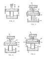
- the filler unit includes an open-topped vessel 10 which has an orifice 12 in its bottom.
- a downpipe 14 communicating with the interior of the vessel 10 through the orifice 12 extends downwardly from the bottom of the vessel.
- the unit is positioned as shown over a container 16 which is to be topped up with liquid dispensed from the vessel to a predetermined, desired level 18.
- the lower end of the downpipe 14 is at a predetermined depth 22 below the level 18.
- the vessel 10 is continuously filled with a liquid 20 which is to be dispensed to the container 16 to top up the liquid 19 accomodated within the container to the desired level 18.
- Means (not shown) are provided for maintaining a substantially constant depth 24 of liquid in the vessel i.e. for establishing a constant static head in the vessel.
- the level of liquid 19 will continue to rise outside the downpipe 14 since the liquid 20 will continue to flow via the orifice 12.
- the rising liquid 19 will begin to exert a pressure against the air-liquid boundary at the bottom of the downpipe.
- the air pressure within the downpipe will consequently begin to rise.
- the flow of liquid via the orifice is reduced progressively until the i air pressure within the downpipe becomes equal to the pressure of the liquid at the orifice.
- the pressure of the liquid passing through the orifice is created by the head of liquid 20 above the orifice.
- the upward pressure has risen to match the downward pressure, the flow of liquid via the orifice will cease automatically,
- the upward pressure acting against the liquid at the orifice is created by the liquid depth 22. Neglecting the effects of air compression, material distortion etc., and assuming a uniform liquid specific gravity, the liquid depth 22 will be equal to the liquid depth 24 at the point of pressure equilibrium. In practice, air compression plays a small but significant 5 part and
- the unit will operate automatically to restore the pressure equilibrium condition once more and to restore the liquid level in the container to the desired level 18.
- a single vessel 10 can therefore be used to fill a number of containers, with attendant savings in cost and complexity.
- the length of the downpipes can be different to each other and still produce acceptable level control in each container, but the vessel 10 should not be operated other than level without special baffles, liquid retention sponges or the like for equalising or compensating the pressures at all the orifices.
- the orifice 12 may have virtually any size or shape, provided that it is not too small to permit liquid to pass through it or not too large for surface tension effects to develop.
- Figure 4 shows one alternative orifice configuration in which there are a series of spaced apart orifices 12A, 12B and so on.
- Figure 5 shows another configuration in which multiple orifices are provided by a fibre packing 12C.
- a pipe 26 is used to supply the vessel 10 continuously with liquid.
- the depth of liquid 20 in the vessel is regulated by means of an overflow 28 which is positioned to ensure that the depth of the liquid i.e. the static head is correct for achieving the pressure equilibrium condition when the level 18 is reached in the container 16. Excess liquid overflows to waste or for recycling. When flow through the orifice ceases, all inflowing liquid from the pipe 26 will overflow.
- a float 30 within the vessel 10, with a needle 32 carried by the float.
- a pipe 34 which conveys liquid to the vessel 10 has a branch pipe 36 providing a valve seat 38 which is complementary in shape to the needle 32.
- the float 30 remains on the bottom of the vessel 10 when the inflow to the vessel from the branch pipe 36 is less than the outflow through the orifice 12.
- the t inflow exceeds the outflow, there will be an accumulation of liquid within the vessel 10, which results in the float rising.
- the needle will seat tightly against the valve seat to prevent further inflow through the branch pipe 36.
- Units according to the embodiment of Figure 7 can be arranged in series, with each unit being supplied with liquid from the pipe 34. Each unit will operate independently to control the level of liquid within its container 16.
- the needle and valve seat should be of a soft material which will allow for a liquid-tight seal between the parts. Also, the mating parts of the needle and valve seat should be matched to one I another with accuracy to ensure a reliable seal. The pressure of the liquid in the pipe 28 and the branch pipe 36 should obviously not be sufficient to drive the needle away from its seat once the equilibrium condition is attained. Of course, the materials chosen for the float and valve components should be resistant to corrosive attack by the ) liquids used in the unit.
- FIG 8 incorporates the regulating features of both the embodiments of Figures 6 and 7.
- the vessel 10 is provided with an overflow 28 similar to that of Figure 6, together with a valve arrangement similar to that of Figure 7.
- the overflow 28 provides extra security in the regulation of the liquid level in the vessel, since the overflow is positioned very slightly above the required level of liquid in the vessel, so that if the valve fails to close properly, only a small inaccuracy in the depth of liquid will arise.
- Figure 9 illustrates the situation when the liquid 20 is overflowing at the overflow 28.
- valve arrangements could also be used to prevent liquid inflow to the vessel 10 when the equilibrium situation is attaned.
- overflow has been described and illustrated as provided by the upper edges of the walls of the vessel, other types of overflow, such as an overflow-pipe or weir, could also be used.
- FIG. 10 shows a further, preferred modification.
- a baffle plate 40 situated near to the bottom of the vessel 10 over the orifice 12.
- the space between the baffle plate and the bottom of the vessel is small enough to encourage capillary action of the liquid 20. This allows the liquid 20 to flow through to the orifice, but serves to retain a film of liquid even if the vessel 10 should be emptied.
- One effect of this feature is that an effective seal is created between the downpipe 14 and the vessel 10.
- the seal provides a cap for the downpipe 14 so that it will always contain the correct volume of air despite liquid level fluctuations in the container 16 or movement of the vessel 10 with consequent movement of the downpipe in a manner which covers and uncovers the open lower end of the downpipe.
- the capillary action under the baffle plate 40 has the effect of raising the apparent position of the orifice 12 within vessel 10.
- the depth 24 of liquid within the vessel is now measured from the surface of the4.. liquid to the edge of the baffle plate, which is the boundary of the capillary action.
- This effect is advantageous since it reduces the height restriction on the vessel 10, and permits a higher vessel construction to perform as if it were a lower vessel.
- the float 30 can be positioned higher up in the vessel and the overflow 28 can similarly be positioned higher up in the vessel.
- the- depth 24 can be decreased.
- the depth 22 can also be decreased as a result. This leads to a greater degree of repeatibility and accuracy in controlling the total depth of liquid in the container 16.
- baffle plate 40 could alternatively be placed below the orifice to produce some of these advantages, for example, retention of liquid- to provide a seal.
- baffle plates and orifices could be stacked to improve liquid retention and alter the relative position of the orifice.
- FIG. 11 Each of the embodiments described so far has application in the topping up of the secondary cells of a battery or a series of batteries.
- the embodiment of Figure 11 is especially adapted for this purpose.
- the unit is fitted with a sleeve 41 provided with a thread 42 (see Figures 12 and 13) which allows the unit to be fitted to the top 44 of the battery housing at the conventional threaded apertures.
- the unit has a baffle plate 40 and a float valve arrangement and an overflow 28.
- the unit is modified by the provision of breather pipes 46 which allow evaporation from the interior of the container or cell 16 to escape into the vessel 10.
- breather pipes 46 At the upper ends of the breather pipes 46, there are condensation chambers 47 in ) which some of the evaporated gases are condensed.
- the condensate is able to return to the vessel 10 for re-use via escape holes 48. some of the returning condensate will serve to keep the float 30 wet, and hence improve its floating stability.
- the returning condensate will also serve to provide the liquid seal in the capillary passage between the baffle 40 and the bottom of the vessel.
- the liquid 19 in the cell may be caused to form a spray or mist when in use, but most of the liquid lost in this way will be recovered in the vessel 10.
- the vessel 10 is fitted with a cap 50 which is of 0 slightly larger diameter than the outside diameter than the walls of the vessel. Liquid which overflows the vessel at the overflow 28 is able to escape through the gap between the cap and the vessel walls.
- a method which has been in use for many years of cooling a propagated flame can easily be incorporated into the filler unit.
- a suitable medium is used to cool the flame sufficiently for it to be extinguished.
- the medium usually comprises a porous ceramic substance or a small gap between two spaced surfaces, which will allow gases to permeate or pass through but will, at the same time, cool the gases very rapidly of they are hotter than the cooling medium.
- Suitable positions for such a flame cooling medium within the construction of the filler unit are the following: the overflow 28, which necessitates the use of a medium which does not restrict the passage of gas and liquid unduly; the escape holes 48 which would also enhance the process of condensation if a medium pervious to gas and impervious to liquid is employed; the breather pipes 46, which would necessitiate the use of more permeable material than that used inside the escape holes; the space below the baffle plate 40 or within the orifice 12 or as substitute for the baffle plate or orifice or both, in which case only liquid and no gas should be able to pass though; or within the downpipe 14 or in the space between the downpipe 12 and the sleeve 14.
- the filler unit of Figures 11 to 13 can be one of a series of such filler units each associated with a single one of the cells of a battery or batteries of cells.
- the pipe 34 can continue from one filler unit to the next in series. So that each independent filler unit can be removed from its cell when required, the pipe 34 may be flexible, and there should be a degree of slack in the pipe allowing the unit to be unscrewed. As depicted in the Figures the pipe 34 is only of short length, and could be of rigid construction, allowing flexible lengths of pipe to be connected between the ends of adjacent pipes 34 of adjacent units.
Landscapes
- Chemical & Material Sciences (AREA)
- Chemical Kinetics & Catalysis (AREA)
- Electrochemistry (AREA)
- General Chemical & Material Sciences (AREA)
- Filling, Topping-Up Batteries (AREA)
- Manufacture Of Motors, Generators (AREA)
- Separation Using Semi-Permeable Membranes (AREA)
- Feeding, Discharge, Calcimining, Fusing, And Gas-Generation Devices (AREA)
Priority Applications (1)
| Application Number | Priority Date | Filing Date | Title |
|---|---|---|---|
| AT84300424T ATE33527T1 (de) | 1983-01-26 | 1984-01-25 | Fuelleinheit zum auffuellen eines behaelters mit fluessigkeit. |
Applications Claiming Priority (2)
| Application Number | Priority Date | Filing Date | Title |
|---|---|---|---|
| ZA830502 | 1983-01-26 | ||
| ZA83502 | 1983-01-26 |
Publications (2)
| Publication Number | Publication Date |
|---|---|
| EP0115423A1 true EP0115423A1 (de) | 1984-08-08 |
| EP0115423B1 EP0115423B1 (de) | 1988-04-13 |
Family
ID=25576509
Family Applications (1)
| Application Number | Title | Priority Date | Filing Date |
|---|---|---|---|
| EP84300424A Expired EP0115423B1 (de) | 1983-01-26 | 1984-01-25 | Fülleinheit zum Auffüllen eines Behälters mit Flüssigkeit |
Country Status (5)
| Country | Link |
|---|---|
| US (1) | US4544004A (de) |
| EP (1) | EP0115423B1 (de) |
| AT (1) | ATE33527T1 (de) |
| AU (1) | AU566206B2 (de) |
| DE (1) | DE3470444D1 (de) |
Cited By (1)
| Publication number | Priority date | Publication date | Assignee | Title |
|---|---|---|---|---|
| CN110494364A (zh) * | 2016-10-25 | 2019-11-22 | 西纳林克公司 | 填注杯子的方法和设备,杯子的包装作业线 |
Families Citing this family (12)
| Publication number | Priority date | Publication date | Assignee | Title |
|---|---|---|---|---|
| DE3574344D1 (en) * | 1984-08-29 | 1989-12-28 | Omron Tateisi Electronics Co | Ultrasonic atomizer |
| WO1995006960A1 (en) * | 1993-08-30 | 1995-03-09 | Haig Katazian | Battery feeder |
| EP0972153A4 (de) * | 1997-03-13 | 2004-10-06 | Trojan Battery Co | Flüssigkeitsfüllvorrichtung |
| US6427732B1 (en) | 1998-06-12 | 2002-08-06 | Johan Christiaan Fitter | Filler unit for automatically topping up a container with liquid |
| US6095206A (en) * | 1998-11-18 | 2000-08-01 | William E. M. Jones | Automatic liquid filling device and method of filling to a predetermined level |
| DE10036462A1 (de) | 1999-07-26 | 2001-05-17 | Johan Christiaan Fitter | Befüllsystem für Mehrfachbehälter |
| US6446681B1 (en) * | 1999-08-24 | 2002-09-10 | Johan Christiaan Fitter | Filler unit for topping up a container with liquid |
| GB2399215B (en) * | 2000-03-20 | 2004-10-27 | Johan C Fitter | Method and apparatus for achieving prolonged battery life |
| GB2376560B (en) | 2000-03-20 | 2004-10-27 | Johan C Fitter | Method and apparatus for achieving prolonged battery life |
| US6675842B1 (en) | 2002-05-28 | 2004-01-13 | Fitter Johan C | Fluid delivery system |
| US20060105230A1 (en) * | 2004-11-17 | 2006-05-18 | Johan Fitter | Automated battery watering control system |
| US20070240782A1 (en) * | 2006-04-13 | 2007-10-18 | Fitter Johan C | System and method for preparing a flowable mixture for a battery |
Citations (2)
| Publication number | Priority date | Publication date | Assignee | Title |
|---|---|---|---|---|
| GB350285A (en) * | 1929-07-11 | 1931-06-11 | Georges Marconnet | Improvements relating to arrangements for the automatic filling of receptacles, especially electric accumulators |
| FR2311412A1 (fr) * | 1975-05-14 | 1976-12-10 | Europ Accumulateurs | Bouchon de remplissage pour batterie d'accumulateurs |
Family Cites Families (3)
| Publication number | Priority date | Publication date | Assignee | Title |
|---|---|---|---|---|
| US518306A (en) * | 1894-04-17 | William albert clark | ||
| US4079761A (en) * | 1975-02-24 | 1978-03-21 | Herbst Sr Clarence A | Battery water filling device |
| US4176694A (en) * | 1978-03-27 | 1979-12-04 | Donald R. Dickerson | Automatic shutoff liquid dispensing valve |
-
1984
- 1984-01-24 US US06/573,035 patent/US4544004A/en not_active Expired - Lifetime
- 1984-01-25 EP EP84300424A patent/EP0115423B1/de not_active Expired
- 1984-01-25 AT AT84300424T patent/ATE33527T1/de not_active IP Right Cessation
- 1984-01-25 AU AU23769/84A patent/AU566206B2/en not_active Expired
- 1984-01-25 DE DE8484300424T patent/DE3470444D1/de not_active Expired
Patent Citations (2)
| Publication number | Priority date | Publication date | Assignee | Title |
|---|---|---|---|---|
| GB350285A (en) * | 1929-07-11 | 1931-06-11 | Georges Marconnet | Improvements relating to arrangements for the automatic filling of receptacles, especially electric accumulators |
| FR2311412A1 (fr) * | 1975-05-14 | 1976-12-10 | Europ Accumulateurs | Bouchon de remplissage pour batterie d'accumulateurs |
Cited By (2)
| Publication number | Priority date | Publication date | Assignee | Title |
|---|---|---|---|---|
| CN110494364A (zh) * | 2016-10-25 | 2019-11-22 | 西纳林克公司 | 填注杯子的方法和设备,杯子的包装作业线 |
| CN110494364B (zh) * | 2016-10-25 | 2021-09-14 | 西纳林克公司 | 填注杯子的方法和设备,杯子的包装作业线 |
Also Published As
| Publication number | Publication date |
|---|---|
| DE3470444D1 (en) | 1988-05-19 |
| EP0115423B1 (de) | 1988-04-13 |
| AU2376984A (en) | 1985-08-01 |
| US4544004A (en) | 1985-10-01 |
| AU566206B2 (en) | 1987-10-15 |
| ATE33527T1 (de) | 1988-04-15 |
Similar Documents
| Publication | Publication Date | Title |
|---|---|---|
| US4544004A (en) | Filler unit for topping up a container with liquid | |
| US4472256A (en) | Electrolytic pool chlorinator | |
| CN214494207U (zh) | 内浮顶氮封储液罐 | |
| KR900019061A (ko) | 원자로 격납 설비로부터의 패시브 열 제거 시스템 | |
| US2585878A (en) | Skimming apparatus | |
| US4353213A (en) | Side stream type condensing system and method of operating the same | |
| NO134751B (de) | ||
| US4022687A (en) | Method for the non-mechanical conveying of a collected quantity of liquid and apparatus for the performance of the method | |
| US4657651A (en) | Vertical gas electrode operation | |
| NO131869B (de) | ||
| US4531456A (en) | Liquid distribution trough | |
| ES8701507A1 (es) | Perfeccionamientos en un dispositivo para el desgasificado de un fluido liquido | |
| NO139250B (no) | Oljeutskiller for separering av olje fra vann ved tyngdekraft | |
| US2055645A (en) | Storage battery | |
| EP0043821A1 (de) | Vorrichtung zur rückgewinnung von metallen aus lösungen. | |
| FR2426288A1 (fr) | Procede de regulation de la flottabilite d'un receptacle et receptacle | |
| US5030032A (en) | Apparatus for producing water seal in protective tube of the submersed pump of gas cistern | |
| US899738A (en) | Evaporator. | |
| US6446681B1 (en) | Filler unit for topping up a container with liquid | |
| JPH0610988B2 (ja) | 積層形燃料電池の電解液補給装置 | |
| GB1591731A (en) | Degassing apparatus | |
| US4599624A (en) | Atmospheric pressure chamber in an ink jet system printer | |
| GB2246277A (en) | Plant holder and waterer | |
| US380589A (en) | Charles edwaed o keen an | |
| US795753A (en) | Means for supplying water under constant pressure to freezing-plates. |
Legal Events
| Date | Code | Title | Description |
|---|---|---|---|
| PUAI | Public reference made under article 153(3) epc to a published international application that has entered the european phase |
Free format text: ORIGINAL CODE: 0009012 |
|
| AK | Designated contracting states |
Designated state(s): AT BE CH DE FR GB IT LI LU NL SE |
|
| 17P | Request for examination filed |
Effective date: 19850204 |
|
| GRAA | (expected) grant |
Free format text: ORIGINAL CODE: 0009210 |
|
| AK | Designated contracting states |
Kind code of ref document: B1 Designated state(s): AT BE CH DE FR GB IT LI LU NL SE |
|
| REF | Corresponds to: |
Ref document number: 33527 Country of ref document: AT Date of ref document: 19880415 Kind code of ref document: T |
|
| ITF | It: translation for a ep patent filed | ||
| REF | Corresponds to: |
Ref document number: 3470444 Country of ref document: DE Date of ref document: 19880519 |
|
| ET | Fr: translation filed | ||
| PLBE | No opposition filed within time limit |
Free format text: ORIGINAL CODE: 0009261 |
|
| STAA | Information on the status of an ep patent application or granted ep patent |
Free format text: STATUS: NO OPPOSITION FILED WITHIN TIME LIMIT |
|
| 26N | No opposition filed | ||
| REG | Reference to a national code |
Ref country code: GB Ref legal event code: 732 |
|
| REG | Reference to a national code |
Ref country code: FR Ref legal event code: TP |
|
| ITTA | It: last paid annual fee | ||
| PGFP | Annual fee paid to national office [announced via postgrant information from national office to epo] |
Ref country code: CH Payment date: 19931126 Year of fee payment: 11 |
|
| PGFP | Annual fee paid to national office [announced via postgrant information from national office to epo] |
Ref country code: SE Payment date: 19931130 Year of fee payment: 11 |
|
| PGFP | Annual fee paid to national office [announced via postgrant information from national office to epo] |
Ref country code: LU Payment date: 19931201 Year of fee payment: 11 |
|
| PGFP | Annual fee paid to national office [announced via postgrant information from national office to epo] |
Ref country code: BE Payment date: 19931202 Year of fee payment: 11 |
|
| EPTA | Lu: last paid annual fee | ||
| PGFP | Annual fee paid to national office [announced via postgrant information from national office to epo] |
Ref country code: AT Payment date: 19940131 Year of fee payment: 11 Ref country code: NL Payment date: 19940131 Year of fee payment: 11 |
|
| PGFP | Annual fee paid to national office [announced via postgrant information from national office to epo] |
Ref country code: FR Payment date: 19950110 Year of fee payment: 12 |
|
| PGFP | Annual fee paid to national office [announced via postgrant information from national office to epo] |
Ref country code: DE Payment date: 19950121 Year of fee payment: 12 |
|
| PG25 | Lapsed in a contracting state [announced via postgrant information from national office to epo] |
Ref country code: LU Free format text: LAPSE BECAUSE OF NON-PAYMENT OF DUE FEES Effective date: 19950125 Ref country code: AT Effective date: 19950125 |
|
| PG25 | Lapsed in a contracting state [announced via postgrant information from national office to epo] |
Ref country code: SE Effective date: 19950126 |
|
| EAL | Se: european patent in force in sweden |
Ref document number: 84300424.3 |
|
| PG25 | Lapsed in a contracting state [announced via postgrant information from national office to epo] |
Ref country code: BE Effective date: 19950131 Ref country code: CH Effective date: 19950131 Ref country code: LI Effective date: 19950131 |
|
| BERE | Be: lapsed |
Owner name: FITTER JOHAN CHRISTIAAN Effective date: 19950131 |
|
| PG25 | Lapsed in a contracting state [announced via postgrant information from national office to epo] |
Ref country code: NL Effective date: 19950801 |
|
| REG | Reference to a national code |
Ref country code: CH Ref legal event code: PL |
|
| NLV4 | Nl: lapsed or anulled due to non-payment of the annual fee |
Effective date: 19950801 |
|
| EUG | Se: european patent has lapsed |
Ref document number: 84300424.3 |
|
| PG25 | Lapsed in a contracting state [announced via postgrant information from national office to epo] |
Ref country code: FR Effective date: 19960930 |
|
| PG25 | Lapsed in a contracting state [announced via postgrant information from national office to epo] |
Ref country code: DE Effective date: 19961001 |
|
| REG | Reference to a national code |
Ref country code: FR Ref legal event code: ST |
|
| REG | Reference to a national code |
Ref country code: GB Ref legal event code: IF02 |
|
| PGFP | Annual fee paid to national office [announced via postgrant information from national office to epo] |
Ref country code: GB Payment date: 20030122 Year of fee payment: 20 |
|
| PG25 | Lapsed in a contracting state [announced via postgrant information from national office to epo] |
Ref country code: GB Free format text: LAPSE BECAUSE OF EXPIRATION OF PROTECTION Effective date: 20040124 |
|
| REG | Reference to a national code |
Ref country code: GB Ref legal event code: PE20 |