EP0115518B1 - Sicherheitshaken - Google Patents
Sicherheitshaken Download PDFInfo
- Publication number
- EP0115518B1 EP0115518B1 EP83902642A EP83902642A EP0115518B1 EP 0115518 B1 EP0115518 B1 EP 0115518B1 EP 83902642 A EP83902642 A EP 83902642A EP 83902642 A EP83902642 A EP 83902642A EP 0115518 B1 EP0115518 B1 EP 0115518B1
- Authority
- EP
- European Patent Office
- Prior art keywords
- hook
- pawl
- hole
- retention device
- safety
- Prior art date
- Legal status (The legal status is an assumption and is not a legal conclusion. Google has not performed a legal analysis and makes no representation as to the accuracy of the status listed.)
- Expired
Links
- 230000014759 maintenance of location Effects 0.000 claims description 13
- 230000000694 effects Effects 0.000 description 3
- 238000004519 manufacturing process Methods 0.000 description 3
- 208000031968 Cadaver Diseases 0.000 description 2
- 238000009826 distribution Methods 0.000 description 2
- 238000005553 drilling Methods 0.000 description 2
- 238000009776 industrial production Methods 0.000 description 2
- 206010061876 Obstruction Diseases 0.000 description 1
- 238000005452 bending Methods 0.000 description 1
- 239000000470 constituent Substances 0.000 description 1
- 239000000463 material Substances 0.000 description 1
- 239000004576 sand Substances 0.000 description 1
- 238000005303 weighing Methods 0.000 description 1
Images

Classifications
-
- B—PERFORMING OPERATIONS; TRANSPORTING
- B66—HOISTING; LIFTING; HAULING
- B66C—CRANES; LOAD-ENGAGING ELEMENTS OR DEVICES FOR CRANES, CAPSTANS, WINCHES, OR TACKLES
- B66C1/00—Load-engaging elements or devices attached to lifting or lowering gear of cranes or adapted for connection therewith for transmitting lifting forces to articles or groups of articles
- B66C1/10—Load-engaging elements or devices attached to lifting or lowering gear of cranes or adapted for connection therewith for transmitting lifting forces to articles or groups of articles by mechanical means
- B66C1/22—Rigid members, e.g. L-shaped members, with parts engaging the under surface of the loads; Crane hooks
- B66C1/34—Crane hooks
- B66C1/36—Crane hooks with means, e.g. spring-biased detents, for preventing inadvertent disengagement of loads
-
- F—MECHANICAL ENGINEERING; LIGHTING; HEATING; WEAPONS; BLASTING
- F16—ENGINEERING ELEMENTS AND UNITS; GENERAL MEASURES FOR PRODUCING AND MAINTAINING EFFECTIVE FUNCTIONING OF MACHINES OR INSTALLATIONS; THERMAL INSULATION IN GENERAL
- F16B—DEVICES FOR FASTENING OR SECURING CONSTRUCTIONAL ELEMENTS OR MACHINE PARTS TOGETHER, e.g. NAILS, BOLTS, CIRCLIPS, CLAMPS, CLIPS OR WEDGES; JOINTS OR JOINTING
- F16B45/00—Hooks; Eyes
- F16B45/02—Hooks with pivoting or elastically bending closing member
- F16B45/023—Hooks with pivoting or elastically bending closing member the closing member pivoting about an axis perpendicular to the plane of the hook
Definitions
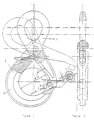
- the present invention relates to safety hooks and more particularly. those provided with a latch articulated on the body of the hook in the upper part and opening towards the outside of said hook according to FIG. 1.
- the safety hook is held by the upper part of the latch. Under tension, the latch is closed automatically, the free end of the latch coming into contact with the point of the hook body and preventing any accidental release of the load.
- the known improvements consist in making a hook shape on the ends of the hook body and of the pawl such that when the pawl is closed, the hook shapes secure the pawl and the body of the hook. (See GB-A-111 850 by VOORWINDE).
- the latch thus contributes to directly supporting part of the load and constitutes a retention of the end of the body of the hook, prevents it from bending under the effect of the load, and makes it possible to lighten the body of the hook.
- Patents or safety hook projects describing a latch-hook attachment system are extremely numerous. Despite this, no hook of this type has known or is currently experiencing a significant distribution. Most have experienced industrial or commercial failure.
- the object of the present invention is to remedy the drawbacks of these hooks. It aims to better distribute the stresses in the constituent parts of the hook, reduce the weight of the hooks, and allow industrial and inexpensive manufacturing, while ensuring increased security.
- the invention therefore relates to safety hooks provided with a latch articulated on the body of the hook in its upper part and opening towards the outside of said hook and provided with a device for retaining the free end of the body of the hook by the free end of the latch, so that, under load, the body of the hook does not deform prematurely and characterized in that this retaining device consists of a flat contact face on each of the parts: latch and body, these plane faces receiving one, a prominence having the shape of a cylinder whose axis is perpendicular to said plane face, the other a hole of cylindrical shape whose axis is perpendicular to said plane face, of dimensions larger than said cylinder and located so that when the hook is closed, the cylinder enters the cylindrical hole. Conversely, the cylinder can be found on the body and the hole on the hook latch.
- this retaining device is oriented in such a way that the angle having for apex the point defined by the intersection is either of the axis of the cylinder, or that of the cylindrical hole, either one or the other of the generators of contact of the cylinder and of the cylindrical hole with the contact plane of the ends of the latch and of the hook body, and for sides: on the one hand, one or the other of said axes and generators, on the other hand, a straight line connecting said vertex to the axis of articulation of the pawl and the body of the hook, and opening towards the interior space formed between the pawl and the body of the hook , or less than 90 °,
- this angle must have a value between 80 and 90 °.
- the clearance between the cylinder and the cylindrical hole must be between 0.02 and 0.04 times the diameter of the inscribable circle in the interior space defined by the hook and the hook body.
- the retaining device according to the invention also has the advantage of being able to be produced in a very economical manner industrially by stamping the body of the hook and of the latch and by drilling the cylindrical hole.
- the cylindrical hole could take a slightly flattened shape by mechanical crushing of the end of the body of the hook or of the latch at a very low cost in industrial process.
- the cylinder could also have an equivalent shape.
- the cylindrical hole is through.
- the safety hook according to the invention has a mechanical operation which is fundamentally different from the existing hooks and has the fundamental advantage of much less weight and easier and less dangerous handling.
- the described safety hook comprises a latch (1) articulated on the body of the hook (2).
- the free ends of the latch and of the hook body each have a flat contact face (f, f ') passing through the hinge axis of the latch and of the hook body.
- the flat face of the end of the pawl has a cylindrical pin with an axis perpendicular to the flat face.
- the flat face of the hook body has a cylindrical hole drilled and emerging with a diameter slightly greater than that of the pin and with an axis perpendicular to the flat face.
- the hook described also has the advantage of being simple and inexpensive industrial production by stamping the. latch and hook body, the cylindrical hole being obtained by drilling with a drill.
- this safety hook has decisive advantages over those known, in particular by its weight, the ease and safety of its handling, the simplicity and the low cost of its industrial production.
- the invention is applicable to all safety hooks provided with a latch articulated on the body of the hook in its upper part and opening towards the outside of said hook, in particular those manufactured industrially and intended for all industries, building , public works, agriculture and in general to all activities requiring the lifting of loads.
Landscapes
- Engineering & Computer Science (AREA)
- General Engineering & Computer Science (AREA)
- Mechanical Engineering (AREA)
- Hooks, Suction Cups, And Attachment By Adhesive Means (AREA)
- Emergency Lowering Means (AREA)
Claims (6)
Applications Claiming Priority (2)
| Application Number | Priority Date | Filing Date | Title |
|---|---|---|---|
| FR8214027A FR2531414B1 (fr) | 1982-08-06 | 1982-08-06 | Perfectionnement aux crochets de securite |
| FR8214027 | 1982-08-06 |
Publications (2)
| Publication Number | Publication Date |
|---|---|
| EP0115518A1 EP0115518A1 (de) | 1984-08-15 |
| EP0115518B1 true EP0115518B1 (de) | 1986-12-03 |
Family
ID=9276817
Family Applications (1)
| Application Number | Title | Priority Date | Filing Date |
|---|---|---|---|
| EP83902642A Expired EP0115518B1 (de) | 1982-08-06 | 1983-08-08 | Sicherheitshaken |
Country Status (5)
| Country | Link |
|---|---|
| US (1) | US4554712A (de) |
| EP (1) | EP0115518B1 (de) |
| DE (1) | DE3368041D1 (de) |
| FR (1) | FR2531414B1 (de) |
| WO (1) | WO1984000744A1 (de) |
Families Citing this family (12)
| Publication number | Priority date | Publication date | Assignee | Title |
|---|---|---|---|---|
| USD297878S (en) | 1985-06-03 | 1988-09-27 | Gunnebo Ab | Safety hook |
| USD297877S (en) | 1985-06-03 | 1988-09-27 | Gunnebo Ab | Safety hook |
| US4977647A (en) * | 1989-10-27 | 1990-12-18 | D.B. Industries, Inc. | Double locking snap hook |
| JP2833674B2 (ja) * | 1991-08-02 | 1998-12-09 | 澄子 松山 | 重量物吊上げ用フック装置 |
| ES2265211B1 (es) * | 2004-02-09 | 2008-01-01 | Encofrados J. Alsina, S.A. | Gancho para encofrados. |
| US7895817B2 (en) * | 2009-05-14 | 2011-03-01 | The United States Of America As Represented By The Secretary Of The Army | Tool-less chain coupling link |
| US8752254B2 (en) | 2012-02-28 | 2014-06-17 | D B Industries, Llc | Snap hook |
| US8746766B2 (en) | 2012-06-07 | 2014-06-10 | Randy Lewkoski | Hook assembly |
| US9707419B2 (en) | 2014-10-08 | 2017-07-18 | D B Industries, Llc | Snap hook |
| US10066660B2 (en) | 2015-10-22 | 2018-09-04 | Reliance Industries, Llc | Rebar snap hook |
| US11767198B2 (en) * | 2020-04-08 | 2023-09-26 | Liko Research & Development Ab | Sling bars, methods for attaching a subject sling to sling bars, and lift systems using sling bars |
| US20240245247A1 (en) * | 2023-01-21 | 2024-07-25 | Brittany Scott | Hook for Suspending a Purse |
Family Cites Families (18)
| Publication number | Priority date | Publication date | Assignee | Title |
|---|---|---|---|---|
| US453877A (en) * | 1891-06-09 | Clarence p | ||
| US701586A (en) * | 1901-09-14 | 1902-06-03 | Robert W Levitt | Snap-hook. |
| US1088614A (en) * | 1911-12-19 | 1914-02-24 | Martin T Olstad | Hook. |
| US1291673A (en) * | 1918-01-24 | 1919-01-14 | George Brennan | Safety-hook. |
| US1373235A (en) * | 1920-05-13 | 1921-03-29 | Murphy H Giberson | Safety-hook for logs |
| US1411857A (en) * | 1920-09-15 | 1922-04-04 | Maiden Albert | Snap hook |
| US1390023A (en) * | 1921-06-11 | 1921-09-06 | Austin L Coon | Safety-hook |
| US1441378A (en) * | 1922-07-10 | 1923-01-09 | John F Selvidge | Hook |
| GB200029A (en) * | 1922-12-23 | 1923-07-05 | Albert Holger Hertz | Improvements connected with hooks for use with lifting tackle and the like |
| US1465804A (en) * | 1923-03-14 | 1923-08-21 | Albert C Bubb | Coupling device |
| US1688176A (en) * | 1927-07-11 | 1928-10-16 | Clark John | Connecter |
| US1725609A (en) * | 1928-07-11 | 1929-08-20 | Amos Herman | Hoisting hook |
| US1716997A (en) * | 1928-10-31 | 1929-06-11 | Antoniow Tassos | Logging hook |
| GB550162A (en) * | 1941-10-30 | 1942-12-24 | Percy Charles Barton | Improvements connected with hooks |
| FR946394A (fr) * | 1947-05-02 | 1949-06-01 | Dispositif de sécurité pour crochets d'appareils de levage | |
| FR1574978A (de) * | 1968-07-17 | 1969-07-18 | ||
| DE2614961C3 (de) * | 1976-04-07 | 1979-02-01 | Brueggemann & Brand Kg, 5802 Wetter | Karabinerhaken, insbesondere zum Transport von schweren Außenlasten an Hubschraubern |
| FR2409955A1 (fr) * | 1977-11-24 | 1979-06-22 | Altabe Edmond | Crochet de manutention auto-verrouillant et auto-porteur |
-
1982
- 1982-08-06 FR FR8214027A patent/FR2531414B1/fr not_active Expired
-
1983
- 1983-08-08 DE DE8383902642T patent/DE3368041D1/de not_active Expired
- 1983-08-08 EP EP83902642A patent/EP0115518B1/de not_active Expired
- 1983-08-08 WO PCT/FR1983/000166 patent/WO1984000744A1/fr not_active Ceased
- 1983-08-08 US US06/604,647 patent/US4554712A/en not_active Expired - Fee Related
Also Published As
| Publication number | Publication date |
|---|---|
| WO1984000744A1 (fr) | 1984-03-01 |
| DE3368041D1 (en) | 1987-01-15 |
| FR2531414A1 (fr) | 1984-02-10 |
| FR2531414B1 (fr) | 1986-04-11 |
| EP0115518A1 (de) | 1984-08-15 |
| US4554712A (en) | 1985-11-26 |
Similar Documents
| Publication | Publication Date | Title |
|---|---|---|
| EP1465507B1 (de) | Schnalle zur selbstverriegelung und einstellungsfestlegung eines gürtels | |
| FR2645699A1 (fr) | Crochet d'accouplement, notamment pour les barres inferieures d'un attelage trois points d'un tracteur | |
| FR2857709A1 (fr) | Mousqueton a deux doigts opposes | |
| WO1984000744A1 (fr) | Perfectionnements aux crochets de securite | |
| FR2864198A1 (fr) | Vanne de securite comportant un mecanisme de fermeture utilisant un ressort travaillant en extension | |
| FR2705064A1 (fr) | Crochet d'accouplement pour les bras inférieurs d'un dispositif d'attelage trois points d'un tracteur. | |
| WO2001068986A1 (fr) | Ancrage reglable pour cable portant une structure de genie civil | |
| CA3011509A1 (fr) | Anneau de levage pivotant pour le levage de charges | |
| EP0698189A1 (de) | Fernbediente vorrichtung zur schnellkupplung und entkupplung | |
| EP0002396B1 (de) | Lasthaken | |
| FR2688822A1 (fr) | Dispositif de fixation d'un operateur pour la commande d'ouverture et de fermeture d'un vantail de porte ou portail. | |
| EP0050079B1 (de) | Mit einer Verzahnung versehene Gelenkvorrichtung zur Sicherheitsentriegelung | |
| FR3087418A1 (fr) | Systeme de fixation d'un siege | |
| EP0679143B1 (de) | Hebering | |
| FR2491901A3 (fr) | Crochet de securite | |
| EP0085631A1 (de) | Sicherheitshaken | |
| EP0014148B1 (de) | Sicherheitshaken | |
| FR2531130A1 (fr) | Serrure du type a armement, notamment pour le verrouillage du capot ou du coffre d'un vehicule automobile | |
| FR2638094A1 (fr) | Perfectionnements aux dispositifs de securite pour ouvrier travaillant dans des endroits eleves | |
| EP1191174B1 (de) | Sicherheitsvorrichtung für Ladenhaken | |
| FR2555398A1 (fr) | Crochets d'attelage automatiques destines a etre places aux extremites des bielles d'attelage a trois points | |
| FR2545074A1 (fr) | Anneau de levage | |
| FR2519394A1 (fr) | Crochet de securite | |
| EP0217901A1 (de) | Kupplung und entkupplung mit sicherheitsverriegelung und öffnung durch kraftzylinder unterstützt | |
| FR2505004A1 (fr) | Mousqueton du type a verrouillage par bague a vis, et procede d'assemblage du mousqueton |
Legal Events
| Date | Code | Title | Description |
|---|---|---|---|
| PUAI | Public reference made under article 153(3) epc to a published international application that has entered the european phase |
Free format text: ORIGINAL CODE: 0009012 |
|
| AK | Designated contracting states |
Designated state(s): BE CH DE FR GB LI NL SE |
|
| 17P | Request for examination filed |
Effective date: 19840821 |
|
| GRAA | (expected) grant |
Free format text: ORIGINAL CODE: 0009210 |
|
| AK | Designated contracting states |
Kind code of ref document: B1 Designated state(s): BE CH DE FR GB LI NL SE |
|
| PG25 | Lapsed in a contracting state [announced via postgrant information from national office to epo] |
Ref country code: SE Effective date: 19861231 |
|
| REF | Corresponds to: |
Ref document number: 3368041 Country of ref document: DE Date of ref document: 19870115 |
|
| PG25 | Lapsed in a contracting state [announced via postgrant information from national office to epo] |
Ref country code: LI Effective date: 19870831 Ref country code: CH Effective date: 19870831 |
|
| PGFP | Annual fee paid to national office [announced via postgrant information from national office to epo] |
Ref country code: NL Payment date: 19870831 Year of fee payment: 5 |
|
| PLBE | No opposition filed within time limit |
Free format text: ORIGINAL CODE: 0009261 |
|
| STAA | Information on the status of an ep patent application or granted ep patent |
Free format text: STATUS: NO OPPOSITION FILED WITHIN TIME LIMIT |
|
| 26N | No opposition filed | ||
| REG | Reference to a national code |
Ref country code: CH Ref legal event code: PL |
|
| PG25 | Lapsed in a contracting state [announced via postgrant information from national office to epo] |
Ref country code: DE Effective date: 19880503 |
|
| GBPC | Gb: european patent ceased through non-payment of renewal fee | ||
| PG25 | Lapsed in a contracting state [announced via postgrant information from national office to epo] |
Ref country code: GB Free format text: LAPSE BECAUSE OF NON-PAYMENT OF DUE FEES Effective date: 19881122 |
|
| PGFP | Annual fee paid to national office [announced via postgrant information from national office to epo] |
Ref country code: BE Payment date: 19890629 Year of fee payment: 7 |
|
| PG25 | Lapsed in a contracting state [announced via postgrant information from national office to epo] |
Ref country code: NL Effective date: 19900301 |
|
| NLV4 | Nl: lapsed or anulled due to non-payment of the annual fee | ||
| PG25 | Lapsed in a contracting state [announced via postgrant information from national office to epo] |
Ref country code: BE Effective date: 19900831 |
|
| BERE | Be: lapsed |
Owner name: LE BEON ROGER Effective date: 19900831 |
|
| PGFP | Annual fee paid to national office [announced via postgrant information from national office to epo] |
Ref country code: FR Payment date: 19920724 Year of fee payment: 10 |
|
| PG25 | Lapsed in a contracting state [announced via postgrant information from national office to epo] |
Ref country code: FR Effective date: 19940429 |
|
| REG | Reference to a national code |
Ref country code: FR Ref legal event code: ST |