EP0115624A2 - Appareil pour la mesure de tension d'une greffe cutanée - Google Patents
Appareil pour la mesure de tension d'une greffe cutanée Download PDFInfo
- Publication number
- EP0115624A2 EP0115624A2 EP83113044A EP83113044A EP0115624A2 EP 0115624 A2 EP0115624 A2 EP 0115624A2 EP 83113044 A EP83113044 A EP 83113044A EP 83113044 A EP83113044 A EP 83113044A EP 0115624 A2 EP0115624 A2 EP 0115624A2
- Authority
- EP
- European Patent Office
- Prior art keywords
- clamping
- leg
- skin
- spring
- legs
- Prior art date
- Legal status (The legal status is an assumption and is not a legal conclusion. Google has not performed a legal analysis and makes no representation as to the accuracy of the status listed.)
- Withdrawn
Links
- 238000006073 displacement reaction Methods 0.000 abstract description 5
- 230000036558 skin tension Effects 0.000 description 8
- 238000000034 method Methods 0.000 description 3
- 230000035876 healing Effects 0.000 description 2
- 238000005259 measurement Methods 0.000 description 2
- 230000014759 maintenance of location Effects 0.000 description 1
Images

Classifications
-
- A—HUMAN NECESSITIES
- A61—MEDICAL OR VETERINARY SCIENCE; HYGIENE
- A61B—DIAGNOSIS; SURGERY; IDENTIFICATION
- A61B17/00—Surgical instruments, devices or methods
- A61B17/28—Surgical forceps
- A61B17/2812—Surgical forceps with a single pivotal connection
-
- A—HUMAN NECESSITIES
- A61—MEDICAL OR VETERINARY SCIENCE; HYGIENE
- A61B—DIAGNOSIS; SURGERY; IDENTIFICATION
- A61B90/00—Instruments, implements or accessories specially adapted for surgery or diagnosis and not covered by any of the groups A61B1/00 - A61B50/00, e.g. for luxation treatment or for protecting wound edges
- A61B90/06—Measuring instruments not otherwise provided for
-
- A—HUMAN NECESSITIES
- A61—MEDICAL OR VETERINARY SCIENCE; HYGIENE
- A61B—DIAGNOSIS; SURGERY; IDENTIFICATION
- A61B90/00—Instruments, implements or accessories specially adapted for surgery or diagnosis and not covered by any of the groups A61B1/00 - A61B50/00, e.g. for luxation treatment or for protecting wound edges
- A61B90/06—Measuring instruments not otherwise provided for
- A61B2090/064—Measuring instruments not otherwise provided for for measuring force, pressure or mechanical tension
Definitions
- cut or mobilized skin flaps are displaced under tension in a given direction to cover skinless areas. These skin flaps are grasped with surgical tweezers and displaced under tensile stress such that the skin flap edges lie approximately parallel to the boundary edges of the skinless area, so that the parallel edges can then be sewn together.
- the skin tension of the flap to be displaced must be kept in such a way that the subsequent tension on the attached seams does not lead to the suturing being torn open.
- the relief cuts necessary to cut free the skin flap to be displaced should be kept as small as possible. It therefore requires a great deal of surgical experience and tact to carry out these skin shifting techniques in an optimal manner.
- the object of the invention is to propose a suitable device for checking the tensile stress when moving the skin flap.
- a corresponding device which is characterized by a pair of tweezers or pliers-like devices with wide ends on the clamping legs, the clamping legs being individually or jointly non-positively connected to a handle part via tension meters.
- the surgeon is given a device with which he can objectively determine the tension occurring on the skin flap to be displaced during the operation.
- the necessary length of relief cuts On the basis of recognized permissible tensile stresses, it is possible for him to determine the necessary length of relief cuts and to create the optimal prerequisite for the healing success with regard to the "skin tension" factor.
- a preferred embodiment of the device according to the invention is characterized by two tubes which are connected to one another in an articulated manner, in each of which a clamping leg can be telescopically displaced in the pulling direction against a spring fastened in the respective tube with the same spring characteristic, with a length change indicator corresponding to the pulling force being provided on the clamping leg .
- Such a device acts approximately like a spring balance.
- the applied tensile stress, which corresponds to the skin tension can be determined on the basis of the externally recognizable change in length of the clamping legs, which emerge more or less from the tubes.
- the respective mobilized skin flap is brought into its final displacement position. If the displayed tension value is below a permissible size, the seam can then be attached.
- the device according to the invention is primarily used to determine the skin tension that occurs, but if necessary, it can surgical auxiliary device in the manner of surgical tweezers or pliers can be used at the same time.
- a locking device for the tubes forming the handle part is proposed.
- This clamping device can be used to fix the clamping position which detects the skin flap.
- a spreading spring can be arranged between the pipes.
- a device is characterized by two clamp legs which are articulated in a pincer-like manner and can be fixed in the clamped position, one end of which leg is telescopically guided in a grip tube in the pulling direction against a spring and a length change indicator on the leg corresponding to the tensile force is provided.
- the skin flap to be displaced is grasped and clamped.
- the clamp bracket is secured.
- the device is grasped on the handle tube and moved in the necessary direction of displacement, the corresponding clamping leg end being pulled out of the handle tube in accordance with the tensile stress that occurs.
- This length change indicator corresponds with the tensile force or with the skin tension that occurs.
- Such a device is only used to measure skin tension. The actual operative displacement technique is performed with another surgical device after the appropriate skin tension has been determined.
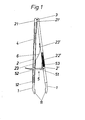
- the tweezer-like device consists of two tubes 2 and 2 'connected to one another at their flattened ends 21 and 21' by a joint 3.
- These widened ends can have anti-slip elements on their inside to ensure the secure retention of the skin flaps seized.
- the clamping legs 1 are over Intermediate tension springs 4 non-positively connected to the tubes 2 and 2 'designed as grip elements.
- corrugations 22 ' are provided on the outside of these tubes to facilitate grip.
- At least on one clamping leg 1, a length change indicator 12 is provided, which corresponds to the change in tensile force. The further the clamping leg 1 is pulled out of the tube 2 against the tension of the spring 4, the greater the tensile force applied and thus the tension on the gripped and displaced skin flaps.
- the locking device designated overall by the number 5 consists of a locking rail 51 suspended on the tube 2 'against a spring 53 and a locking guide 52 correspondingly provided on the other tube 2.
- This device 5 essentially serves to fix the two tubes in the clamping position, so that after gripping the skin flap by the ends 11, the clamping position is secured and only the pull-off force is to be applied.
- Other locking devices are possible.
- a pincer-like device for checking the tensile stress when moving skin flaps is shown.
- the clamp legs 101 and 101 ' which are connected like pliers, are connected approximately centrally by the joint 103.
- the clamping legs are actuated on these handle parts.
- a locking pin 152 provided on the leg 101 engages in the locking sleeve 151 provided on the other leg 101 'of a locking device 1, designated overall by the number 105.
- This locking device also secures the skin flap clamped between the leg ends 111 and 111 '.
- the device is gripped by the two recessed grips 122, which are provided on the tube 102 designed as a grip part.
- the correspondingly designed free end 112 of the clamping leg 101 can in turn be displaced in the manner of a spring balance against the pull of a spring 104.
- Length markings are provided on this cylindrical leg end 112, which form the tensile force display 112a. The tensile force applied corresponds to the protruding length of the end 112 from the tube 102.
- electronically measuring and indicating devices can be used which, for example, work on the principle of strain measurement with digital display.
Landscapes
- Health & Medical Sciences (AREA)
- Surgery (AREA)
- Life Sciences & Earth Sciences (AREA)
- Heart & Thoracic Surgery (AREA)
- Molecular Biology (AREA)
- Veterinary Medicine (AREA)
- Engineering & Computer Science (AREA)
- Biomedical Technology (AREA)
- Nuclear Medicine, Radiotherapy & Molecular Imaging (AREA)
- Medical Informatics (AREA)
- Public Health (AREA)
- Animal Behavior & Ethology (AREA)
- General Health & Medical Sciences (AREA)
- Pathology (AREA)
- Oral & Maxillofacial Surgery (AREA)
- Ophthalmology & Optometry (AREA)
- Force Measurement Appropriate To Specific Purposes (AREA)
- Surgical Instruments (AREA)
Applications Claiming Priority (2)
| Application Number | Priority Date | Filing Date | Title |
|---|---|---|---|
| DE8300262 | 1983-01-07 | ||
| DE8300262U | 1983-01-07 |
Publications (2)
| Publication Number | Publication Date |
|---|---|
| EP0115624A2 true EP0115624A2 (fr) | 1984-08-15 |
| EP0115624A3 EP0115624A3 (fr) | 1985-05-29 |
Family
ID=6748746
Family Applications (1)
| Application Number | Title | Priority Date | Filing Date |
|---|---|---|---|
| EP83113044A Withdrawn EP0115624A3 (fr) | 1983-01-07 | 1983-12-23 | Appareil pour la mesure de tension d'une greffe cutanée |
Country Status (1)
| Country | Link |
|---|---|
| EP (1) | EP0115624A3 (fr) |
Cited By (5)
| Publication number | Priority date | Publication date | Assignee | Title |
|---|---|---|---|---|
| GB2193141A (en) * | 1985-12-12 | 1988-02-03 | Ernest Mark Talbot | Tension measuring forceps |
| FR2630904A2 (fr) * | 1988-05-05 | 1989-11-10 | Chastenet De Castaing Guillaum | Jumeleur de pinces a dissequer |
| FR2640870A1 (fr) * | 1988-12-26 | 1990-06-29 | Kabbara Jamil | |
| US5176702A (en) * | 1991-04-04 | 1993-01-05 | Symbiosis Corporation | Ratchet locking mechanism for surgical instruments |
| CN111110258A (zh) * | 2020-01-10 | 2020-05-08 | 西安交通大学医学院第一附属医院 | 可调式皮肤张力测定器 |
Family Cites Families (3)
| Publication number | Priority date | Publication date | Assignee | Title |
|---|---|---|---|---|
| DE2025868C3 (de) * | 1970-05-27 | 1975-03-06 | Fa. Walter Peters, 5650 Solingen | Klemm- oder Haltezange, insbesondere für chirurgische Zwecke |
| FR2166839A5 (fr) * | 1972-05-10 | 1973-08-17 | Bras Jean | |
| US3828438A (en) * | 1972-09-08 | 1974-08-13 | J Raymond | Surveying tape tensioning and leveling apparatus |
-
1983
- 1983-12-23 EP EP83113044A patent/EP0115624A3/fr not_active Withdrawn
Cited By (5)
| Publication number | Priority date | Publication date | Assignee | Title |
|---|---|---|---|---|
| GB2193141A (en) * | 1985-12-12 | 1988-02-03 | Ernest Mark Talbot | Tension measuring forceps |
| FR2630904A2 (fr) * | 1988-05-05 | 1989-11-10 | Chastenet De Castaing Guillaum | Jumeleur de pinces a dissequer |
| FR2640870A1 (fr) * | 1988-12-26 | 1990-06-29 | Kabbara Jamil | |
| US5176702A (en) * | 1991-04-04 | 1993-01-05 | Symbiosis Corporation | Ratchet locking mechanism for surgical instruments |
| CN111110258A (zh) * | 2020-01-10 | 2020-05-08 | 西安交通大学医学院第一附属医院 | 可调式皮肤张力测定器 |
Also Published As
| Publication number | Publication date |
|---|---|
| EP0115624A3 (fr) | 1985-05-29 |
Similar Documents
| Publication | Publication Date | Title |
|---|---|---|
| DE2300840C3 (de) | Gerät zur Vorbereitung von Ligaturen der Eileiter | |
| EP0019062A1 (fr) | Serrure de cerclage pour relier les bouts d'un fil de cerclage pour fractures des os et moyen de fixation pour maintenir la serrure | |
| DE3835192A1 (de) | Verfahren zur bespannung von schlaegern fuer ballspiele sowie vorrichtung zur durchfuehrung des verfahrens | |
| EP0115624A2 (fr) | Appareil pour la mesure de tension d'une greffe cutanée | |
| DE619302C (de) | Werkzeug zum Entfernen der Isolierung von Kabeladern und anderen elektrischen Leitungen | |
| DE4133966C1 (fr) | ||
| DE112010002599T5 (de) | An einem Spannzeug befestigter Schutzschild | |
| DE4100219A1 (de) | Klemmenapplikator | |
| EP0563531B1 (fr) | Méthode et dispositif pour effectuer des essais de pelage ou de déchirement sur une plaque soudée | |
| DE102015012397A1 (de) | Teleskopgreifzange | |
| DE8300262U1 (de) | Vorrichtung zum Prüfen der Zugspannung beim Verschieben von Hautlappen | |
| DE3030444A1 (de) | Verfahren und werkzeug zum entfernen eines ringlaeufers vom ring einer ringspinn- oder ringzwirnmaschine | |
| EP2944267A1 (fr) | Dispositif de traction de fil chirurgical | |
| DE3212119C2 (de) | Vorrichtung zum Schließen und Halten von Ballons | |
| DE69104515T2 (de) | Schneidezange mit kleiner Sperre zum Schneiden von optischen Fasern. | |
| EP2906854B1 (fr) | Broche | |
| DE2936474A1 (de) | Vorrichtung zur stufenlosen abdichtung von schlauchfoermigen gebilden | |
| DE2655042C2 (de) | Knotvorrichtung | |
| EP1034715A2 (fr) | Dispositif pour lier des produits en faisceau | |
| DE1503218A1 (de) | Tragbares Werkzeug zur Herstellung von Stossverbindungen,Spleissverbindungen,Ringen od.dgl. | |
| DE839479C (de) | Zugvorrichtung fuer Draehte, Seile u. dgl. | |
| DE3032236C2 (de) | Zange zum Verbinden der Drahtenden bei der Drahtosteosynthese | |
| DE612488C (de) | Haarwellgeraet | |
| EP0259394A1 (fr) | Outil de pose de cables. | |
| DE2754575C2 (de) | Osteosynthese-Zuggurtungslitze |
Legal Events
| Date | Code | Title | Description |
|---|---|---|---|
| PUAI | Public reference made under article 153(3) epc to a published international application that has entered the european phase |
Free format text: ORIGINAL CODE: 0009012 |
|
| AK | Designated contracting states |
Designated state(s): AT BE CH DE FR GB IT LI LU NL SE |
|
| PUAL | Search report despatched |
Free format text: ORIGINAL CODE: 0009013 |
|
| 17P | Request for examination filed |
Effective date: 19850205 |
|
| AK | Designated contracting states |
Designated state(s): AT BE CH DE FR GB IT LI LU NL SE |
|
| 17Q | First examination report despatched |
Effective date: 19860728 |
|
| R17C | First examination report despatched (corrected) |
Effective date: 19861114 |
|
| STAA | Information on the status of an ep patent application or granted ep patent |
Free format text: STATUS: THE APPLICATION HAS BEEN WITHDRAWN |
|
| 18W | Application withdrawn |
Withdrawal date: 19870718 |