EP0115801B1 - Attache d'une soupape de vidange dans un réservoir de chasse d'eau - Google Patents
Attache d'une soupape de vidange dans un réservoir de chasse d'eau Download PDFInfo
- Publication number
- EP0115801B1 EP0115801B1 EP84100592A EP84100592A EP0115801B1 EP 0115801 B1 EP0115801 B1 EP 0115801B1 EP 84100592 A EP84100592 A EP 84100592A EP 84100592 A EP84100592 A EP 84100592A EP 0115801 B1 EP0115801 B1 EP 0115801B1
- Authority
- EP
- European Patent Office
- Prior art keywords
- housing
- seal
- outlet
- projection
- wall
- Prior art date
- Legal status (The legal status is an assumption and is not a legal conclusion. Google has not performed a legal analysis and makes no representation as to the accuracy of the status listed.)
- Expired
Links
- XLYOFNOQVPJJNP-UHFFFAOYSA-N water Substances O XLYOFNOQVPJJNP-UHFFFAOYSA-N 0.000 description 5
- 230000000712 assembly Effects 0.000 description 4
- 238000000429 assembly Methods 0.000 description 4
- 238000009434 installation Methods 0.000 description 4
- 238000009428 plumbing Methods 0.000 description 4
- 238000000034 method Methods 0.000 description 3
- 238000012986 modification Methods 0.000 description 2
- 230000004048 modification Effects 0.000 description 2
- 238000007789 sealing Methods 0.000 description 2
- 238000004140 cleaning Methods 0.000 description 1
- 230000006835 compression Effects 0.000 description 1
- 238000007906 compression Methods 0.000 description 1
- 230000000694 effects Effects 0.000 description 1
- 239000003292 glue Substances 0.000 description 1
- 238000004519 manufacturing process Methods 0.000 description 1
- 230000007246 mechanism Effects 0.000 description 1
- 238000003825 pressing Methods 0.000 description 1
- 238000005476 soldering Methods 0.000 description 1
- 238000003860 storage Methods 0.000 description 1
Images


Classifications
-
- E—FIXED CONSTRUCTIONS
- E03—WATER SUPPLY; SEWERAGE
- E03D—WATER-CLOSETS OR URINALS WITH FLUSHING DEVICES; FLUSHING VALVES THEREFOR
- E03D1/00—Water flushing devices with cisterns ; Setting up a range of flushing devices or water-closets; Combinations of several flushing devices
- E03D1/30—Valves for high or low level cisterns; Their arrangement ; Flushing mechanisms in the cistern, optionally with provisions for a pre-or a post- flushing and for cutting off the flushing mechanism in case of leakage
- E03D1/34—Flushing valves for outlets; Arrangement of outlet valves
Definitions
- the present invention relates to flush valves that control the outflow of water from a toilet tank and, more particularly, to an attachment system for connecting a flush valve to a wall of a toilet tank.
- the invention is especially useful in connection with «one piece» toilets that are constructed so that there is no easy way to reach the underside of the bottom wall of the tank after the toilet has been manufactured, which greatly complicates the atachment of a flush valve to the «blind hole» at the bottom of the tank.
- a well-known type of toilet is one in which the water storage tank and toilet bowl are formed in two separate pieces.
- Such toilets often have a washer placed around an outlet formed in the bottom of the tank, and a valve housing mounted on the washer and through the washer and outlet.
- the housing is usually formed with a threaded lower end that extends below the tank bottom wall.
- a nut is provided which is suitable to be screwed onto these threads (from below the tank wall), so that the nut abuts against the underside of the tank bottom wall. While this flush valve assembly has proved generally satisfactory for «two piece» toilets, the plumbing industry is always interested in ways to further reduce the amount of time required for installation.
- Another type of known toilet is the «one piece» toliet.
- the underside of the tank bottom wall is not accessible. This is because a channel from the tank to the toilet bowl and/or a toilet siphon leg is cast directly underneath the tank.
- valve housing is provided with outwardly projecting lugs which are adapted to pass through notches at the periphery of the opening.
- the housing is then rotated 90° and a lock nut is applied to exterior threading on the housing.
- the object of the invention is providing a flush valve attachment system of the above kind which can be attached to a blind hole formed in a wall of a toilettank and which provides a water-tight seal with the tank wall when the valve is closed. Further, the object is to provide a flush valve attachment system in which the housing does not require external threading and the separate assembly of a lock nut.
- the present invention provides a flush valve attachment system for connecting a flush valve to a wall of a toilet tank, having a non-circular outlet formed in the wall of the tank, a resilient seal bearing against an interior side of the wall, the seal surrounding the outlet and having a central bore aligned therewith, a flush valve having a housing that extends through the seal bore and outlet, said housing having a radially outwardly extending projection on the exterior side of the wall and said housing being rotatable between a first position in which the projection can pass through the outlet, and a second position where the projection can catch on the exterior side of the wall, characterized by said housing having a radially outwardly extending flange inward of the seal to trap the seal against the wall, and a stop member formed on the outside of the housing between the resilient seal and the projection, the stop member interacting with the periphery of the outlet to limit rotation of the housing relative to the outlet.
- the projection comprises a plurality of projecting members equally spaced from each other around the outside of the housing, and there are a plurality of stop members formed on the outside of the housing between the resilient seal and each projecting member. These stop members are suitable to interact with the periphery of the outlet to limit rotation of the housing relative to the outlet. They also insure that the housing is properly centered in the outlet.
- the present invention allows a user to easily install a flush valve by placing a seal over a tank outlet hole, pushing a specially constucted valve housing through the seal and outlet, turning the housing in the outlet, and releasing the housing. If the procedure is reversed, the flush valve can be removed.
- the user need not have any direct access to the underside of the tank bottom wall to install or remove the flush valve.
- the underside of the tank wall need not be specially adapted or altered.
- flush valve attachment system of the invention is relatively inexpensive to produce and install, and can be used by a consumer who has little training in the plumbing arts.
- a «one piece» toilet 10 consists of a tank portion 11, a bowl portion 12, and a siphon portion 13. As is conventional with such toilets, the tank has a bottom wall 14, and an outlet hole 15 formed in the bottom wall.
- a flush valve assembly referred to generally by numeral 16, includes a conventional overflow tube 17, and a conventional flapper 18 attached onto conventional hooks 10 on the sides of the tube. It should be understood that the flapper 18 is moved onto and off its seat by one of the many known trip mechanisms (not shown). In this regard, when the tank is to be refilled, the flapper will be in the position shown in Fig. 1, and when water is to be let out of the tank, the flapper will be lifted off its seat (usually through use of a chain attached to the top of the flapper).
- a non-circular outlet 15 is formed in the bottom wall 14 of the tank.
- the hole is a contoured triangle.
- the non-circular hole 20 is almost circular, but it has a series of non-circular distortions or cutouts 21.
- the term «non-circular» is used herein, it is intended to cover all shapes other than a simple circular hole.
- Resilient, axially compressible seal 23 is also provided. It has a lower sealing surface 24 and a central through bore 25. As shown in Fig. 2, the lower sealing surface 24 bears against the topside or interior surface 26 of the tank bottom wall 14. The seal 23 can then surround and seal the outlet 15 when the bore 25 is aligned over the outlet 15.
- the flush valve 16 has a housing portion 27 which extends through the seal bore 25 and outlet 15.
- This housing has a channel 30 therethrough, a valve seat 31 at the upper end of the channel, and an exit port 32 atthe exit portion of the channel 30.
- Flange 33 extends radially outwardly from the housing 27, above the seal 23, so as to compress and trap the seal 23 against the top of the tank bottom wall 26. It should be understood that the flange need not be a continuous rim. Instead, it could be one or more projections.
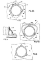
- Three radially outwardly extending projections 38 extend below the bottom wall 14 on the exterior of the tank, so as to catch under the wall when in the position shown in Fig. 4A, and so as to be able to fit through the outlet 15 when the projections 38 are aligned with the corners 39 of the hole 15. (See e.g. Fig. 6).
- these projections are spaced apart from each other an equal distance so as to provide a balanced attachment, and they are permanently fixed relative to said housing, so as to extend radially outward. It should be understood that when the word «permanently» is used in this context, it is meant to indicate that the projection is fixed relative to the housing during installation and during normal use.
- Stop members 40 are best shown in Figs. 3, 4A and 5. They are formed directly over the projections 38, and below the resilient seal 23. They are suitable to interact with the periphery of the outlet 15, so as to limit rotation of the housing 27 relative to the outlet. See Fig. 4A. This prevents an installer from turning the housing too far during installation.
- the stops 40 allow the flush valve to correct for outlets that are cut slightly large or small.
- line 41 in Fig. 4B represents the size of outlet 15 in Fig. 4A.
- Line 42 represents a slightly oversized outlet.
- the flush valve 16 To install the flush valve 16, one places the resilient seal 23 over the outlet 15, and inserts the projections 38 through the seal bore 25. By aligning the projections 38 appropriately, the projections can then pass through the widest diameter points 39 of the outlet 15, to the underside of the wall 14.
- the seal 23 can first be placed around the housing.
- the projections can then be properly aligned with the outlet 15. From viewing Fig. 2, it can be seen that in this especially preferred form the projections 38 extend farther radially outward from the housing 27 than the through bore 25 of seal 23 does. This prevents the seal 23 from easily falling off of the housing 27 and being lost when the valve 16 is stored or shipped. It also allows easy handling of the assembly when this preferred assembly method is used.
Landscapes
- Health & Medical Sciences (AREA)
- Life Sciences & Earth Sciences (AREA)
- Engineering & Computer Science (AREA)
- Hydrology & Water Resources (AREA)
- Public Health (AREA)
- Water Supply & Treatment (AREA)
- Sanitary Device For Flush Toilet (AREA)
Claims (6)
Applications Claiming Priority (2)
| Application Number | Priority Date | Filing Date | Title |
|---|---|---|---|
| US06/461,437 US4433446A (en) | 1983-01-27 | 1983-01-27 | Flush valve attachment system |
| US461437 | 1983-01-27 |
Publications (2)
| Publication Number | Publication Date |
|---|---|
| EP0115801A1 EP0115801A1 (fr) | 1984-08-15 |
| EP0115801B1 true EP0115801B1 (fr) | 1986-08-27 |
Family
ID=23832556
Family Applications (1)
| Application Number | Title | Priority Date | Filing Date |
|---|---|---|---|
| EP84100592A Expired EP0115801B1 (fr) | 1983-01-27 | 1984-01-20 | Attache d'une soupape de vidange dans un réservoir de chasse d'eau |
Country Status (8)
| Country | Link |
|---|---|
| US (1) | US4433446A (fr) |
| EP (1) | EP0115801B1 (fr) |
| JP (1) | JPH0615778B2 (fr) |
| KR (1) | KR920000451B1 (fr) |
| CA (1) | CA1213405A (fr) |
| DE (1) | DE3460521D1 (fr) |
| ES (1) | ES529188A0 (fr) |
| MX (1) | MX158050A (fr) |
Families Citing this family (13)
| Publication number | Priority date | Publication date | Assignee | Title |
|---|---|---|---|---|
| CH674863A5 (fr) * | 1988-03-17 | 1990-07-31 | Geberit Ag | |
| WO1989011570A1 (fr) * | 1988-05-16 | 1989-11-30 | Joseph Robin Orbell | Robinet de chasse d'eau pour reservoirs |
| FR2669058B1 (fr) * | 1990-11-14 | 1993-09-03 | Spmp Sa | Mecanisme perfectionne de chasse d'eau sanitaire. |
| WO1993014275A1 (fr) * | 1992-01-07 | 1993-07-22 | Societe Phoceenne De Matieres Plastiques - Spmp (Sa) | Mecanisme perfectionne de chasse d'eau sanitaire |
| US5353445A (en) * | 1993-02-16 | 1994-10-11 | Kohler Co. | Conduit attachment system |
| US5848442A (en) * | 1997-11-05 | 1998-12-15 | Kohler Co. | Flush valve attachment system |
| US6192526B1 (en) | 1999-10-05 | 2001-02-27 | Lavelle Industries, Inc. | Top mounted flush valve for a toilet tank |
| US6651264B2 (en) * | 2002-02-14 | 2003-11-25 | Kohler Co. | Flush valve attachment system with low-profile outlet end |
| US7676858B2 (en) * | 2005-02-22 | 2010-03-16 | Kohler Co. | Flush valve |
| US8806669B2 (en) | 2008-04-10 | 2014-08-19 | Kohler Co. | Toilet flush valve with reducing cross section valve seat |
| JP2010084443A (ja) * | 2008-09-30 | 2010-04-15 | Toto Ltd | 洗浄水タンクの排水弁装置、及び、排水弁装置の排水弁 |
| US12163322B2 (en) | 2020-05-08 | 2024-12-10 | Kohler Co. | One-piece toilet with flush valve |
| US11306469B2 (en) | 2020-05-08 | 2022-04-19 | Kohler Co. | One-piece toilet with flush valve |
Family Cites Families (14)
| Publication number | Priority date | Publication date | Assignee | Title |
|---|---|---|---|---|
| US240833A (en) | 1881-05-03 | martin | ||
| US1542703A (en) * | 1924-05-29 | 1925-06-16 | Kirkham Walter Joseph | Water closet |
| US2096307A (en) | 1937-03-18 | 1937-10-19 | Abingdon Sanitary Mfg Co | Combined closet bowl and tank structure |
| US2096306A (en) | 1937-03-18 | 1937-10-19 | Abingdon Sanitary Mfg Co | Combined closet bowl and tank structure |
| US2756078A (en) | 1952-09-26 | 1956-07-24 | Karl A Klingler | Resilient outlet connectors for plumbing fixtures and tanks |
| US2744258A (en) * | 1954-01-29 | 1956-05-08 | Andrew W Harkness | Flush valve and valve outlet |
| US2773268A (en) | 1954-06-24 | 1956-12-11 | American Radiator & Standard | Flush valve |
| US2915762A (en) | 1957-04-10 | 1959-12-08 | Stanley E Kivela | Drain plug |
| US3368224A (en) | 1965-11-04 | 1968-02-13 | Wallace Murray Corp | Toilet tank flush valve |
| US3520233A (en) * | 1969-01-30 | 1970-07-14 | Jaromir Tobias | Low friction radial piston pump or motor |
| US4000526A (en) | 1975-03-26 | 1977-01-04 | Biela John A | Toilet flushing apparatus |
| US4067074A (en) | 1976-06-16 | 1978-01-10 | Stanley Harrison | Water saver flush valve mechanism |
| US4145772A (en) | 1977-07-11 | 1979-03-27 | Trayco, Inc. | Plastic toilet |
| US4365365A (en) | 1981-08-27 | 1982-12-28 | Antunez Bruce A | Flush valve and means for mounting the same |
-
1983
- 1983-01-27 US US06/461,437 patent/US4433446A/en not_active Expired - Lifetime
-
1984
- 1984-01-20 DE DE8484100592T patent/DE3460521D1/de not_active Expired
- 1984-01-20 EP EP84100592A patent/EP0115801B1/fr not_active Expired
- 1984-01-26 CA CA000446117A patent/CA1213405A/fr not_active Expired
- 1984-01-26 MX MX200150A patent/MX158050A/es unknown
- 1984-01-26 ES ES529188A patent/ES529188A0/es active Granted
- 1984-01-27 JP JP59013210A patent/JPH0615778B2/ja not_active Expired - Lifetime
- 1984-01-27 KR KR1019840000368A patent/KR920000451B1/ko not_active Expired
Also Published As
| Publication number | Publication date |
|---|---|
| KR840007260A (ko) | 1984-12-06 |
| CA1213405A (fr) | 1986-11-04 |
| EP0115801A1 (fr) | 1984-08-15 |
| US4433446A (en) | 1984-02-28 |
| ES8506371A1 (es) | 1985-07-01 |
| JPH0615778B2 (ja) | 1994-03-02 |
| DE3460521D1 (en) | 1986-10-02 |
| JPS59177434A (ja) | 1984-10-08 |
| KR920000451B1 (ko) | 1992-01-14 |
| ES529188A0 (es) | 1985-07-01 |
| MX158050A (es) | 1988-12-29 |
Similar Documents
| Publication | Publication Date | Title |
|---|---|---|
| EP0115801B1 (fr) | Attache d'une soupape de vidange dans un réservoir de chasse d'eau | |
| US5745931A (en) | Method and means for covering the flange of a waste water strainer | |
| US10329752B2 (en) | Overflow assembly for bathtubs and the like | |
| US4850063A (en) | Water closet fastener | |
| US6175971B1 (en) | Shower drain | |
| EP1434917B1 (fr) | Ensemble d'ecoulement muni d'un guide d'obturateur servant d'auxiliaire de montage | |
| US3027416A (en) | Electrical outlet box | |
| CA2290858C (fr) | Systeme de fixation au sol pour toilettes | |
| US4420844A (en) | Vandal resistant drain stopper | |
| US5031659A (en) | Sewer line relief valve | |
| US3349917A (en) | Strainer assembly for floor drains | |
| US5353445A (en) | Conduit attachment system | |
| GB2338184A (en) | Plug for a liquid container | |
| US20090010736A1 (en) | Washer | |
| CA2288035C (fr) | Couverture du rebord de l'orifice d'evacuation des eaux usees | |
| WO1998035176A1 (fr) | Joint d'etancheite | |
| US2298551A (en) | Back water valve | |
| US20070186336A1 (en) | Toilet flanges and the mounting thereof | |
| US2710621A (en) | Vacuum breakers | |
| KR200275841Y1 (ko) | 맨홀의 속뚜껑 잠금장치 | |
| JPS5915787Y2 (ja) | 弁体 | |
| JPS6027194Y2 (ja) | 便器洗浄用ロ−タンク | |
| KR102051087B1 (ko) | 싱크대용 배수장치 | |
| JPS6046305B2 (ja) | 過流出防止弁 | |
| KR200438490Y1 (ko) | 세면기 배수 밸브 장치 |
Legal Events
| Date | Code | Title | Description |
|---|---|---|---|
| PUAI | Public reference made under article 153(3) epc to a published international application that has entered the european phase |
Free format text: ORIGINAL CODE: 0009012 |
|
| AK | Designated contracting states |
Designated state(s): DE FR GB IT |
|
| 17P | Request for examination filed |
Effective date: 19840806 |
|
| GRAA | (expected) grant |
Free format text: ORIGINAL CODE: 0009210 |
|
| AK | Designated contracting states |
Kind code of ref document: B1 Designated state(s): DE FR GB IT |
|
| REF | Corresponds to: |
Ref document number: 3460521 Country of ref document: DE Date of ref document: 19861002 |
|
| ET | Fr: translation filed | ||
| ITF | It: translation for a ep patent filed | ||
| PLBE | No opposition filed within time limit |
Free format text: ORIGINAL CODE: 0009261 |
|
| STAA | Information on the status of an ep patent application or granted ep patent |
Free format text: STATUS: NO OPPOSITION FILED WITHIN TIME LIMIT |
|
| 26N | No opposition filed | ||
| ITTA | It: last paid annual fee | ||
| PGFP | Annual fee paid to national office [announced via postgrant information from national office to epo] |
Ref country code: FR Payment date: 19951222 Year of fee payment: 13 |
|
| PGFP | Annual fee paid to national office [announced via postgrant information from national office to epo] |
Ref country code: GB Payment date: 19960103 Year of fee payment: 13 |
|
| PGFP | Annual fee paid to national office [announced via postgrant information from national office to epo] |
Ref country code: DE Payment date: 19960109 Year of fee payment: 13 |
|
| PG25 | Lapsed in a contracting state [announced via postgrant information from national office to epo] |
Ref country code: GB Effective date: 19970120 |
|
| GBPC | Gb: european patent ceased through non-payment of renewal fee |
Effective date: 19970120 |
|
| PG25 | Lapsed in a contracting state [announced via postgrant information from national office to epo] |
Ref country code: FR Effective date: 19970930 |
|
| PG25 | Lapsed in a contracting state [announced via postgrant information from national office to epo] |
Ref country code: DE Effective date: 19971001 |
|
| REG | Reference to a national code |
Ref country code: FR Ref legal event code: ST |