EP0115865A1 - Condensateur - Google Patents
Condensateur Download PDFInfo
- Publication number
- EP0115865A1 EP0115865A1 EP84101123A EP84101123A EP0115865A1 EP 0115865 A1 EP0115865 A1 EP 0115865A1 EP 84101123 A EP84101123 A EP 84101123A EP 84101123 A EP84101123 A EP 84101123A EP 0115865 A1 EP0115865 A1 EP 0115865A1
- Authority
- EP
- European Patent Office
- Prior art keywords
- condensate
- condenser
- steam
- hot well
- well part
- Prior art date
- Legal status (The legal status is an assumption and is not a legal conclusion. Google has not performed a legal analysis and makes no representation as to the accuracy of the status listed.)
- Granted
Links
- 239000001301 oxygen Substances 0.000 claims abstract description 19
- 229910052760 oxygen Inorganic materials 0.000 claims abstract description 19
- 230000002000 scavenging effect Effects 0.000 claims abstract description 18
- 239000007789 gas Substances 0.000 claims abstract description 14
- QVGXLLKOCUKJST-UHFFFAOYSA-N atomic oxygen Chemical compound [O] QVGXLLKOCUKJST-UHFFFAOYSA-N 0.000 claims abstract description 13
- 238000001816 cooling Methods 0.000 claims description 13
- 238000000638 solvent extraction Methods 0.000 claims 3
- 238000005192 partition Methods 0.000 description 21
- 239000007921 spray Substances 0.000 description 4
- XLYOFNOQVPJJNP-UHFFFAOYSA-N water Substances O XLYOFNOQVPJJNP-UHFFFAOYSA-N 0.000 description 4
- 230000002159 abnormal effect Effects 0.000 description 2
- 230000005484 gravity Effects 0.000 description 1
- 238000005259 measurement Methods 0.000 description 1
- 230000003134 recirculating effect Effects 0.000 description 1
- 230000000630 rising effect Effects 0.000 description 1
- 239000002918 waste heat Substances 0.000 description 1
Images
Classifications
-
- F—MECHANICAL ENGINEERING; LIGHTING; HEATING; WEAPONS; BLASTING
- F28—HEAT EXCHANGE IN GENERAL
- F28B—STEAM OR VAPOUR CONDENSERS
- F28B9/00—Auxiliary systems, arrangements, or devices
- F28B9/10—Auxiliary systems, arrangements, or devices for extracting, cooling, and removing non-condensable gases
-
- F—MECHANICAL ENGINEERING; LIGHTING; HEATING; WEAPONS; BLASTING
- F28—HEAT EXCHANGE IN GENERAL
- F28B—STEAM OR VAPOUR CONDENSERS
- F28B1/00—Condensers in which the steam or vapour is separate from the cooling medium by walls, e.g. surface condenser
- F28B1/02—Condensers in which the steam or vapour is separate from the cooling medium by walls, e.g. surface condenser using water or other liquid as the cooling medium
-
- Y—GENERAL TAGGING OF NEW TECHNOLOGICAL DEVELOPMENTS; GENERAL TAGGING OF CROSS-SECTIONAL TECHNOLOGIES SPANNING OVER SEVERAL SECTIONS OF THE IPC; TECHNICAL SUBJECTS COVERED BY FORMER USPC CROSS-REFERENCE ART COLLECTIONS [XRACs] AND DIGESTS
- Y10—TECHNICAL SUBJECTS COVERED BY FORMER USPC
- Y10S—TECHNICAL SUBJECTS COVERED BY FORMER USPC CROSS-REFERENCE ART COLLECTIONS [XRACs] AND DIGESTS
- Y10S165/00—Heat exchange
- Y10S165/184—Indirect-contact condenser
- Y10S165/187—Indirect-contact condenser having pump downstream of condenser
Definitions
- the present invention relates to a condenser, and more particularly to, an improvement in a condenser for steam turbine.
- the combined plant in which a steam turbine is driven by making use of the waste heat from a gas turbine, generally relies on only the deaerating function of a condenser itself, without providing any independent deaerator.
- the U.S. Heat Exchange Institute has recommended that the oxygen content in the condensate of the condenser should be 0.03 cm 3 /l
- the condenser of the above type requires about one hour until the oxygen content in the condensate reaches 0.03 cm 3 /l under normal starting conditions (i.e., the time required for deaeration).
- the path, through which the dropping condensate formed in the cooling pipe nest in the condenser flows to reach the outlet of the hot well part, is elongated in order to lengthen the radioactivity attenuation time of the condensate.
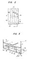
- the cooling pipe nest and the hot well part in the condenser are divided from each other by means of a partition plate, and a plurality of vertical partition plates are disposed in the hot well part to make the condensate meander in the condensate passage.
- the condenser requires much time for deaeration of the condensate in the hot well part, and a long period of time is required for starting of the plant as a whole, disadvantageously.
- a scavenging means for effecting scavenging by means of steam introduced into the atmosphere in the condensate passage in the hot well part. Since the high-oxygen content gas in the atmosphere of the hot well part is expelled by the scavenging means employing steam, it is possible to reduce the time required for deaeration in the condenser. Moreover, the scavenging means prevents the residence of any high-oxygen content gas in the atmosphere of the hot well part; therefore, there is no possibility that oxygen may dissolve into the condensate again, so that it is possible to improve the deaeration performance of the condenser.
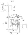
- the steam generated in a boiler 1 is introduced into a steam turbine 3 through a main steam pipe 2.
- a condenser 4 is installed under the steam turbine 3.
- the condenser 4 has therein cooling pipe nests 5a, 5b, and a hot well part 10 formed in the lower part thereof.
- the turbine exhaust from the steam turbine 3 flows into the condenser 4 from the upper side and comes in contact with the cooling pipe nests 5a, 5b to condense into a dropping condensate.
- the condenser 4 has a partition plate 7 for dividing the cooling pipe nests 5a, 5b and the hot well part 10 from each other.
- the partition plate 7 is secured to the front wall 4a, the right wall 4b and the rear wall 4c of the condenser 4 so as to be inclined leftwardly downward, from the right wall 4b to the left wall 4d.,
- the partition plate 7 covers substantially the whole of the inside of the condenser 4 except for the left wall 4d and its vicinity.
- An upper plate 8 is provided above the partition plate 7 and under the cooling pipe nest 5a.
- the upper plate 8, confronting the partition plate . 7, is secured to the left wall 4d, the front wall 4a and the rear wall 4c of the condenser 4.
- the upper plate 8 covers nearly the left half of the inside of the condenser 4 and is slightly inclined rightwardly downward, from the left wall 4d toward the right wall 4b.
- the dropping condensate from the cooling pipe nests 5a, 5b drops onto the upper plate 8 and the partition plate 7 and flows on the partition plate 7 in the form of a thin film-like condensate stream and is then stored in the hot well part 10 as a condensate.
- vertical partition plates 9a, 9b, 9c and 9d are provided between the bottom surface of the condenser 4 and the.partition plate 7. These vertical partition plates 9a, 9b, 9c and 9d are integrated with the partition plate 7.
- the vertical partition plates 9a, 9c are provided extending from the rear wall 4c toward the front wall 4a of the condenser 4 with a distance from the front wall 4a, while the vertical partition plates 9b, 9d are provided extending from the front wall 4a toward the rear wall 4c with a distance from the rear wall 4c.
- the vertical partition plates 9a, 9b, 9c and 9d are disposed in parallel to each other to define a meandering condensate passage 11 in the hot well part 10.
- the condensate passage 11 in the hot well part 10 consists of a condensate inlet, a condensate outlet 16 and a flow section constituted by a continuous tubular space through which the condensate flows while meandering.
- spray devices 12a, 12b are provided, respectively, to spray water so that it comes in contact with the turbine exhaust introduced into the condenser 4.
- the spray device 12a is connected to a condensate recirculating pipe 13, and the spray device 12b to a make-water pipe 14.
- the make-water pipe 14 is connected to a make-water tank 15.
- the condensate flows out from the condensate outlet 16 of the hot well part 10 into a condensate pipe 17.
- the condensate pipe 17 is provided at its intermediate portion with a condensate pump 18 and a gland-steam condenser 19.
- the condensate pipe 17 is connected to the inlet of the boiler 1.
- An auxiliary steam pipe 20 is arranged to branch off from the main steam pipe 2 and communicate with the atmosphere above the condensate in the hot well part 10 through a scavenging auxiliary steam valve 21.
- the auxiliary steam pipe 20 is communicated with the upper space in the vicinity of the condensate outlet 16 of the hot well part 10 of the condenser 4.
- auxiliary steam shown by broken-line arrows
- the auxiliary steam introduced from the auxiliary steam pipe 20 into the atmosphere above the condensate in the hot well part 10 flows counter to the flow of the condensate in the condensate passage 11 in the hot well part 10, that is, in the direction opposite to the direction of flow of the condensate.
- the introduction of the scavenging auxiliary steam stream expels a high-oxygen content gas in the atmosphere above the condensate in the meandering condensate passage 11 in the hot well part 10 and prevents the residence of such a gas. Therefore, there is no possibility that oxygen may dissolve, again, into a fresh condensate successively flowing into the hot well part 10.
- the auxiliary steam stream is guided by the upper plate 8 covering the upper side of the partition plate 7 so as to flow along the surface of the thin film-like condensate stream while deaerating the thin film-like condensate stream.
- the partition plate 7 is provided with a gravity cover-type pressure-relieving means 22.
- the pressure-relieving means 22 is constructed such that an opening also serving as a manhole is formed in the partition plate 7 and covered with a weight in the shape of a manhole cover.
- the pressure-relieving means 22 is adapted to open in order to prevent a rise in pressure when the condensate pump 18 suddenly stops, for example, to cause an abnormal rise in pressure in the space above the condensate in the hot well part 10. Since the pressure-relieving means 22 relieves such an abnormally rising pressure in the space under the partition plate 7 (i.e., the upper space of the hot well part 10) toward the cooling pipe nest 5b, there is no possibility of deformation of the partition plate 7 or abnormal lowering of the condensate level in the hot well part 10.
- the time required until the oxygen content reaches 0.03 cm 3 /l was measured with the scavenging auxiliary steam valve 21 opened to supply the scavenging steam stream.
- the result of the measurement was about 15 minutes.
- the scavenging means which expels the oxygen-containing gas in the condensate passage in the hot well part by means of the scavenging steam, is introduced to expel the high-oxygen content gas in the condenser and prevent the residence of such a gas, so that there is no possibility that oxygen may dissolve into the condensate again.
Landscapes
- Engineering & Computer Science (AREA)
- Mechanical Engineering (AREA)
- General Engineering & Computer Science (AREA)
- Engine Equipment That Uses Special Cycles (AREA)
Applications Claiming Priority (2)
| Application Number | Priority Date | Filing Date | Title |
|---|---|---|---|
| JP58017481A JPS59145484A (ja) | 1983-02-07 | 1983-02-07 | 復水器 |
| JP17481/83 | 1983-02-07 |
Publications (2)
| Publication Number | Publication Date |
|---|---|
| EP0115865A1 true EP0115865A1 (fr) | 1984-08-15 |
| EP0115865B1 EP0115865B1 (fr) | 1986-08-13 |
Family
ID=11945188
Family Applications (1)
| Application Number | Title | Priority Date | Filing Date |
|---|---|---|---|
| EP84101123A Expired EP0115865B1 (fr) | 1983-02-07 | 1984-02-03 | Condensateur |
Country Status (4)
| Country | Link |
|---|---|
| US (1) | US4592419A (fr) |
| EP (1) | EP0115865B1 (fr) |
| JP (1) | JPS59145484A (fr) |
| DE (1) | DE3460441D1 (fr) |
Cited By (3)
| Publication number | Priority date | Publication date | Assignee | Title |
|---|---|---|---|---|
| EP0152920A3 (en) * | 1984-02-14 | 1985-12-11 | Hitachi, Ltd. | Apparatus for deaerating condensate in a condenser |
| EP2218999A4 (fr) * | 2007-12-10 | 2014-05-14 | Toshiba Kk | Condenseur de vapeur |
| CN104341017A (zh) * | 2013-08-07 | 2015-02-11 | 本田技研工业株式会社 | 发动机驱动作业机 |
Families Citing this family (10)
| Publication number | Priority date | Publication date | Assignee | Title |
|---|---|---|---|---|
| JPS59153093A (ja) * | 1983-02-17 | 1984-08-31 | Mitsubishi Heavy Ind Ltd | 復水の脱気方法 |
| DE3717521A1 (de) * | 1987-05-04 | 1988-11-17 | Siemens Ag | Kondensator fuer den wasser-dampf-kreislauf einer kraftwerksanlage, insbesondere kernkraftwerksanlage |
| JPH03275903A (ja) * | 1990-03-23 | 1991-12-06 | Toshiba Corp | 蒸気タービンプラントの起動方法およびその方法に使用する復水装置 |
| DE59101263D1 (de) * | 1990-06-28 | 1994-05-05 | Asea Brown Boveri | Verfahren und Apparat zur Aufwärmung und mehrstufigen Entgasung von Wasser. |
| FI106223B (fi) * | 1996-06-07 | 2000-12-15 | Valmet Corp | Lämmönvaihdin |
| EP1025892A1 (fr) * | 1999-02-04 | 2000-08-09 | ABB Alstom Power (Schweiz) AG | Condenseur à surface |
| JP4931272B2 (ja) * | 2000-11-15 | 2012-05-16 | 株式会社アイ・エイチ・アイ マリンユナイテッド | 箱形浮体の横揺れ低減構造 |
| JP5716233B2 (ja) * | 2010-12-27 | 2015-05-13 | 三菱日立パワーシステムズ株式会社 | 多段圧復水器 |
| CN104058477B (zh) * | 2013-03-22 | 2015-12-30 | 本田技研工业株式会社 | 发动机驱动作业机 |
| CN107246288B (zh) * | 2017-06-16 | 2019-03-05 | 华中科技大学 | 一种透平、凝汽器和循环水泵三合一的能量利用装置 |
Citations (2)
| Publication number | Priority date | Publication date | Assignee | Title |
|---|---|---|---|---|
| US2663547A (en) * | 1949-05-25 | 1953-12-22 | Lummus Co | Condenser deaerator |
| DE1501347A1 (de) * | 1964-11-06 | 1969-05-14 | Komplex Nagyberendezesek Expor | Dampfbeheizte Waermeaustauscher,insbesondere Kondensatoren |
Family Cites Families (6)
| Publication number | Priority date | Publication date | Assignee | Title |
|---|---|---|---|---|
| US1962183A (en) * | 1930-12-06 | 1934-06-12 | Raymond N Ehrhart | Hot well |
| US2756028A (en) * | 1953-09-24 | 1956-07-24 | Westinghouse Electric Corp | Heat exchange apparatus |
| US3094165A (en) * | 1960-01-07 | 1963-06-18 | C H Wheeler Mfg Co | Deaerating system for condensers |
| US3151461A (en) * | 1962-05-07 | 1964-10-06 | Worthington Corp | Means for removing non-condensible gases from boiler feedwater in a power plant |
| US3153329A (en) * | 1962-05-07 | 1964-10-20 | Worthington Corp | Means for removing non-condensible gases from boiler feedwater in a power plant |
| JPS5928279B2 (ja) * | 1976-08-06 | 1984-07-11 | 株式会社日立製作所 | 主復水器 |
-
1983
- 1983-02-07 JP JP58017481A patent/JPS59145484A/ja active Granted
-
1984
- 1984-02-03 DE DE8484101123T patent/DE3460441D1/de not_active Expired
- 1984-02-03 EP EP84101123A patent/EP0115865B1/fr not_active Expired
- 1984-02-06 US US06/577,612 patent/US4592419A/en not_active Expired - Fee Related
Patent Citations (2)
| Publication number | Priority date | Publication date | Assignee | Title |
|---|---|---|---|---|
| US2663547A (en) * | 1949-05-25 | 1953-12-22 | Lummus Co | Condenser deaerator |
| DE1501347A1 (de) * | 1964-11-06 | 1969-05-14 | Komplex Nagyberendezesek Expor | Dampfbeheizte Waermeaustauscher,insbesondere Kondensatoren |
Cited By (4)
| Publication number | Priority date | Publication date | Assignee | Title |
|---|---|---|---|---|
| EP0152920A3 (en) * | 1984-02-14 | 1985-12-11 | Hitachi, Ltd. | Apparatus for deaerating condensate in a condenser |
| EP2218999A4 (fr) * | 2007-12-10 | 2014-05-14 | Toshiba Kk | Condenseur de vapeur |
| US8833744B2 (en) | 2007-12-10 | 2014-09-16 | Kabushiki Kaisha Toshiba | Condenser |
| CN104341017A (zh) * | 2013-08-07 | 2015-02-11 | 本田技研工业株式会社 | 发动机驱动作业机 |
Also Published As
| Publication number | Publication date |
|---|---|
| EP0115865B1 (fr) | 1986-08-13 |
| US4592419A (en) | 1986-06-03 |
| DE3460441D1 (en) | 1986-09-18 |
| JPS6312238B2 (fr) | 1988-03-17 |
| JPS59145484A (ja) | 1984-08-20 |
Similar Documents
| Publication | Publication Date | Title |
|---|---|---|
| EP0115865A1 (fr) | Condensateur | |
| CA1097159A (fr) | Faisceau de tubes | |
| DE1958063C3 (de) | Abscheider | |
| EP0514914B1 (fr) | Système d'injection de vapeur | |
| US3771287A (en) | Deaerating oil tank | |
| EP0049116A2 (fr) | Réchauffeur d'eau d'alimentation | |
| US4726418A (en) | Vacuum condensor with condensate trap | |
| EP0237508B1 (fr) | Purgeur pour un système de conduite fermée | |
| US2860917A (en) | Steam cleaner | |
| US3452518A (en) | Vapour separation systems | |
| US4716014A (en) | Moisture separator for steam generator level measurement system | |
| GB2090963A (en) | Solar powered heating apparatus | |
| JPS6416991A (en) | Nuclear reactor container | |
| US3383288A (en) | Liquid cooled nuclear reactor | |
| US3802398A (en) | Combined condensate return, boiler feed and blowdown tank | |
| US3327774A (en) | Steam surface condenser | |
| JPH0225160B2 (fr) | ||
| JPS6410250B2 (fr) | ||
| JPS5842778Y2 (ja) | ドレン回収処理装置 | |
| JPS6030563Y2 (ja) | 立形給水加熱器 | |
| KR810001736Y1 (ko) | 온수 보일러용 온수 순환 촉진구 | |
| SU1229511A1 (ru) | Регенеративный подогреватель паровой турбины | |
| JPS57131984A (en) | Vapor condensing apparatus | |
| US4585520A (en) | Method and apparatus for closing the vent of an evaporator | |
| JPH09257989A (ja) | 沸騰水型原子炉の給水加熱器 |
Legal Events
| Date | Code | Title | Description |
|---|---|---|---|
| PUAI | Public reference made under article 153(3) epc to a published international application that has entered the european phase |
Free format text: ORIGINAL CODE: 0009012 |
|
| AK | Designated contracting states |
Designated state(s): DE FR GB |
|
| 17P | Request for examination filed |
Effective date: 19840730 |
|
| GRAA | (expected) grant |
Free format text: ORIGINAL CODE: 0009210 |
|
| AK | Designated contracting states |
Kind code of ref document: B1 Designated state(s): DE FR GB |
|
| REF | Corresponds to: |
Ref document number: 3460441 Country of ref document: DE Date of ref document: 19860918 |
|
| ET | Fr: translation filed | ||
| PLBE | No opposition filed within time limit |
Free format text: ORIGINAL CODE: 0009261 |
|
| STAA | Information on the status of an ep patent application or granted ep patent |
Free format text: STATUS: NO OPPOSITION FILED WITHIN TIME LIMIT |
|
| 26N | No opposition filed | ||
| PGFP | Annual fee paid to national office [announced via postgrant information from national office to epo] |
Ref country code: FR Payment date: 19920122 Year of fee payment: 9 |
|
| PGFP | Annual fee paid to national office [announced via postgrant information from national office to epo] |
Ref country code: GB Payment date: 19920124 Year of fee payment: 9 |
|
| PGFP | Annual fee paid to national office [announced via postgrant information from national office to epo] |
Ref country code: DE Payment date: 19920427 Year of fee payment: 9 |
|
| PG25 | Lapsed in a contracting state [announced via postgrant information from national office to epo] |
Ref country code: GB Effective date: 19930203 |
|
| GBPC | Gb: european patent ceased through non-payment of renewal fee |
Effective date: 19930203 |
|
| PG25 | Lapsed in a contracting state [announced via postgrant information from national office to epo] |
Ref country code: FR Effective date: 19931029 |
|
| PG25 | Lapsed in a contracting state [announced via postgrant information from national office to epo] |
Ref country code: DE Effective date: 19931103 |
|
| REG | Reference to a national code |
Ref country code: FR Ref legal event code: ST |