EP0115921A1 - Lampe à déchargeà haute pression - Google Patents
Lampe à déchargeà haute pression Download PDFInfo
- Publication number
- EP0115921A1 EP0115921A1 EP84300305A EP84300305A EP0115921A1 EP 0115921 A1 EP0115921 A1 EP 0115921A1 EP 84300305 A EP84300305 A EP 84300305A EP 84300305 A EP84300305 A EP 84300305A EP 0115921 A1 EP0115921 A1 EP 0115921A1
- Authority
- EP
- European Patent Office
- Prior art keywords
- rod
- wire
- coil
- lamp according
- foil
- Prior art date
- Legal status (The legal status is an assumption and is not a legal conclusion. Google has not performed a legal analysis and makes no representation as to the accuracy of the status listed.)
- Granted
Links
- 239000011888 foil Substances 0.000 claims abstract description 28
- VYPSYNLAJGMNEJ-UHFFFAOYSA-N Silicium dioxide Chemical compound O=[Si]=O VYPSYNLAJGMNEJ-UHFFFAOYSA-N 0.000 claims abstract description 27
- WABPQHHGFIMREM-UHFFFAOYSA-N lead(0) Chemical compound [Pb] WABPQHHGFIMREM-UHFFFAOYSA-N 0.000 claims abstract description 12
- 239000003870 refractory metal Substances 0.000 claims abstract description 10
- 239000005350 fused silica glass Substances 0.000 claims abstract description 9
- ZOKXTWBITQBERF-UHFFFAOYSA-N Molybdenum Chemical compound [Mo] ZOKXTWBITQBERF-UHFFFAOYSA-N 0.000 claims description 13
- 229910052750 molybdenum Inorganic materials 0.000 claims description 10
- 239000011733 molybdenum Substances 0.000 claims description 10
- 229910052721 tungsten Inorganic materials 0.000 claims description 7
- 239000010937 tungsten Substances 0.000 claims description 7
- WFKWXMTUELFFGS-UHFFFAOYSA-N tungsten Chemical compound [W] WFKWXMTUELFFGS-UHFFFAOYSA-N 0.000 claims description 4
- 239000010410 layer Substances 0.000 claims description 2
- 239000002356 single layer Substances 0.000 claims description 2
- 241001529468 Phoca fasciata Species 0.000 abstract description 11
- 238000001816 cooling Methods 0.000 abstract description 5
- 238000004519 manufacturing process Methods 0.000 abstract description 3
- 241000283216 Phocidae Species 0.000 description 12
- 239000000377 silicon dioxide Substances 0.000 description 9
- 230000004048 modification Effects 0.000 description 5
- 238000012986 modification Methods 0.000 description 5
- 230000000712 assembly Effects 0.000 description 3
- 238000000429 assembly Methods 0.000 description 3
- HHIQWSQEUZDONT-UHFFFAOYSA-N tungsten Chemical compound [W].[W].[W] HHIQWSQEUZDONT-UHFFFAOYSA-N 0.000 description 3
- 238000004804 winding Methods 0.000 description 3
- 238000003466 welding Methods 0.000 description 2
- RQFRTWTXFAXGQQ-UHFFFAOYSA-N [Pb].[Mo] Chemical compound [Pb].[Mo] RQFRTWTXFAXGQQ-UHFFFAOYSA-N 0.000 description 1
- 230000015572 biosynthetic process Effects 0.000 description 1
- 238000010276 construction Methods 0.000 description 1
- 239000000463 material Substances 0.000 description 1
- 229910052751 metal Inorganic materials 0.000 description 1
- 239000002184 metal Substances 0.000 description 1
- 238000000034 method Methods 0.000 description 1
- 239000000126 substance Substances 0.000 description 1
Images


Classifications
-
- H—ELECTRICITY
- H01—ELECTRIC ELEMENTS
- H01J—ELECTRIC DISCHARGE TUBES OR DISCHARGE LAMPS
- H01J61/00—Gas-discharge or vapour-discharge lamps
- H01J61/02—Details
- H01J61/36—Seals between parts of vessels; Seals for leading-in conductors; Leading-in conductors
- H01J61/366—Seals for leading-in conductors
-
- H—ELECTRICITY
- H01—ELECTRIC ELEMENTS
- H01J—ELECTRIC DISCHARGE TUBES OR DISCHARGE LAMPS
- H01J9/00—Apparatus or processes specially adapted for the manufacture, installation, removal, maintenance of electric discharge tubes, discharge lamps, or parts thereof; Recovery of material from discharge tubes or lamps
- H01J9/24—Manufacture or joining of vessels, leading-in conductors or bases
- H01J9/32—Sealing leading-in conductors
- H01J9/323—Sealing leading-in conductors into a discharge lamp or a gas-filled discharge device
- H01J9/326—Sealing leading-in conductors into a discharge lamp or a gas-filled discharge device making pinched-stem or analogous seals
Definitions
- This invention relates to high pressure electric discharge lamps of the kind comprising a discharge envelope of fused silica containing a discharge supporting filling, i.e of gas and/or vapour, and a pair of electrodes between which an electric discharge passes in operation of the lamp, and in which electric current is conveyed to the electrodes from the exterior of the envelope via so-called ribbon seals.
- Such a seal comprises, essentially, a strip of refractory metal foil, usually of molybdenum having one end connected electrically to a refractory metal rod which constitutes or provides a support for a respective electrode, and the opposite end connected electrically to at least one further refractory metal rod which projects from the envelope to provide an external lead, the foil and the adjacent ends of the electrode and lead rods being embedded in the envelope wall.
- At least one of the rods of a ribbon seal is surrounded, over at least a part of the region of the rod which is embedded in the envelope wall, by a closely wound coil of relatively thin refractory metal wire.
- the fused silica can be pressed tightly around the rod in the region surrounded by the coil, thereby -preventing any significant movement of the rod, without -giving rise to the same tendency to crack on cooling as the existing forms of lamp employing ribbon-seals as described above.
- closely wound means that adjacent turns of the wire are in contact or are separated by a distance which is less than the wire diameter.
- the wire which is conveniently of tungsten or molybdenum, has a diameter not more than 0.3 mm, and is wound around the rod under tension.
- the wire coil may be held in position on the rod by spot welding or merely by twisting the ends of the wire together, and may be applied as a single layer only, or in two or more layers.
- the foil strip of a ribbon seal may be connected to a plurality of lead rods, and in such a case a said wire coil preferably surrounds at least a part of the embedded region of each of the lead rods.
- both the electrode rod and the lead rod or rods of a ribbon seal are provided with a said wire coil.
- An electrode rod and/or lead-rod over which the wire is wound may have any convenient cross-section as in known ribbon-seal lamps, and-may have flattened ends where joined to the molybdenum foil to give a large area of contact.
- the foil can extend along a region of a rod around which the wire is wound, the wire coil surrounding both the rod and the foil, and serving to hold the foil firmly against the surface of the rod, thereby improving the electrical contact between them. With such a construction the need for welding the foil to the rod may in some cases be avoided.
- the wire coil around an electrode or lead rod need not necessarily be in the form of a simple single strand of wire, but could alternatively be in the form of a coiled coil similar to that used to form the filaments of some electric incandescent lamps, or to form the cathodes of some fluorescent electric discharge lamps.
- Such coiled coils are constructed by winding a filament wire around a wire mandrel, the mandrel being subsequently removed.
- the mandrel may similarly be removed, although, if desired, it may be left in place, the mandrel with the filament coil around it, then being wound around the electrode or lead rod as the case may be.
- the wire may be in the form of a triple coil.
- a coil is formed by winding a filament wire around a first mandrel and then winding the wound mandrel around a further mandrel, one or both mandrels being either left in position or removed.
- the wire employed may be in the form of a multi-stranded or braided wire.
- the wire employed may be in the form of a multi-stranded or braided wire.
- Various other modifications are clearly possible.
- the invention is also applicable to lamps incorporating multifoil seals in which two or more molybdenum foil strips are connected to the electrode rod, with the other ends of the strips each connected to one or more lead rods.
- the lamp illustrated in part in Figures 1 and 2 comprises a tubular discharge envelope 1 of fused silica closed at each end by a pinch seal or a collapsed seal 2 through which is sealed an electrode lead assembly consisting of a strip 3 of molybdenum foil, a tungsten rod 4 which projects into the discharge envelope so as to constitute, or provide a support for, an electrode and which is welded to the inner end of the molybdenum foil strip 3, and a 'molybdenum lead rod 5 welded to the opposite end of the foil strip and projecting from the respective end of the envelope.
- the ends of the rods 4, 5, which are embedded within the material of the seal are surrounded over at least part of their length by a closely wound coil 6 of tungsten or molybdenum wire having a diameter of approximately 0.1 mm.
- the wire is applied to each of the rods under tension so that it conforms closely to the surface thereof.
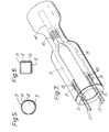
- Figures 3 and 4 illustrate one end of a lamp having a multifoil seal, in a partly formed and completed state respectively.
- the lamp comprises a fused silica envelope consisting of a tubular main part 7 which, in the completed lamp, encompassess the discharge space, and two smaller tubes 8, each of which fits into a respective end of the main part 7 and is closed at its inner end.
- the lamp has a pair of tungsten rod electrodes 4 ' reach connected to one end of a pair of molybdenum foil strips 3 which extend outwards between the inner tubes 8 and the main part 7 of the envelope and are connected at their outer ends to molybdenum lead rods 5 as shown.
- Both electrode rods 4 and the lead rods 5 are surrounded over part of their length by a closely wound coil 6 of tungsten or molybdenum wire, approximately 0.17 mm in diameter, and in order to form the seal the ends of the main part of the envelope are heated to the softening temperature of the silica and allowed to collapse on to the wire wound outer end of the electrode 4 and also on to the respective inner tube 5, so as to embed the foil strip 3 and the adjacent ends of the rods 4, 5 in the collapsed silica, as in Figure 4.
- a closely wound coil 6 of tungsten or molybdenum wire approximately 0.17 mm in diameter
- the silica can be pressed firmly into contact with the rod/coil assemblies without the risk of cracks being formed in the silica on subsequent cooling.
- the inner ends of the foil strips 3 are wrapped partially around the outer end of the electrode rod 4 and both the rod and strips are surrounded by the respective wire coil 6, the latter then serving to hold the strips in firm electrical contact with the surface of the rod.
- the coil 6 around the rod 4 also reinforces the welds which secure the foil strips 3 to the rod, and thereby assists in supporting the rod during assembly of the seal.
- the electrode rod 4 can have any convenient cross-section for example round or square as shown in Figures 5 and 6 respectively.
- Multifoil seals are useful for high current devices, for example 30 amps or above, and the invention is not only applicable to seals incorporating two foil strips but may also be used to advantage in lamps having ribbon seals with a greater number of strips.
- Figure 7 illustrates one end of a high power lamp in which each electrode rod 4 is connected to four molybdenum foil strips 3, secured to the rod in a similar fashion to those of Figures 3 and 4, the overlapping ends of the rod and strips being similarly surrounded by a closely wound coil of tungsten or molybdenum wire 6.
- the outer ends of the strips 3 in this embodiment are each welded to a pair of lead rods 5 and each of these carries a closely wound wire coil 6 as in the previous embodiments.
- a wire coil 6 instead of being wound directly on to an electrode or lead rod, as the case may be, can be preformed and then pushed over the respective rod.
- the wire 6, instead of being in the form of a simple strand, comprises a coiled coil 7 as employed to form the filaments of some forms of incandescent lamps or the cathodes of fluorescent lamps.
- the mandrel on which coil is wound can be removed, as would be the case when the coil is used to form the filament or cathode of such lamps, although in some cases it may be left in, the mandrel, with the coil around on it, then being wound around the electrode or lead rod 4, 5 as the case may be.
- a triple coil may be used as illustrated at 8 in Figure 9, the mandrels either being left in or one or more of them being removed.
- multi-stranded wire 9 as illustrated in Figure 10 or braided wire 10 as in Figure 11 could alternatively be used.
- the invention is applicable to lamps having envelopes of various dimensions and gas/vapour fillings, the precise dimensions and fillings in any particular case depending upon the use to which the lamp is to be put.
Landscapes
- Engineering & Computer Science (AREA)
- Manufacturing & Machinery (AREA)
- Vessels And Coating Films For Discharge Lamps (AREA)
- Discharge Lamp (AREA)
Applications Claiming Priority (2)
| Application Number | Priority Date | Filing Date | Title |
|---|---|---|---|
| GB8303074 | 1983-02-04 | ||
| GB838303074A GB8303074D0 (en) | 1983-02-04 | 1983-02-04 | Electric discharge lamps |
Publications (2)
| Publication Number | Publication Date |
|---|---|
| EP0115921A1 true EP0115921A1 (fr) | 1984-08-15 |
| EP0115921B1 EP0115921B1 (fr) | 1989-07-12 |
Family
ID=10537454
Family Applications (1)
| Application Number | Title | Priority Date | Filing Date |
|---|---|---|---|
| EP84300305A Expired EP0115921B1 (fr) | 1983-02-04 | 1984-01-18 | Lampe à déchargeà haute pression |
Country Status (4)
| Country | Link |
|---|---|
| US (1) | US4550269A (fr) |
| EP (1) | EP0115921B1 (fr) |
| DE (1) | DE3478976D1 (fr) |
| GB (2) | GB8303074D0 (fr) |
Cited By (3)
| Publication number | Priority date | Publication date | Assignee | Title |
|---|---|---|---|---|
| EP0479088A1 (fr) * | 1990-10-02 | 1992-04-08 | Patent-Treuhand-Gesellschaft für elektrische Glühlampen mbH | Lampe à décharge à haute pression et procédé de fabrication |
| EP0858098A3 (fr) * | 1997-02-07 | 1998-10-07 | Stanley Electric Co., Ltd. | Lampe de phare à halogénure métallique |
| EP0762478A3 (fr) * | 1995-08-31 | 1998-11-04 | Osram Sylvania Inc. | Lampe à manchon en verre |
Families Citing this family (16)
| Publication number | Priority date | Publication date | Assignee | Title |
|---|---|---|---|---|
| DE3923589A1 (de) * | 1989-07-17 | 1991-01-24 | Patent Treuhand Ges Fuer Elektrische Gluehlampen Mbh | Hochdruckentladungslampe |
| DE9206314U1 (de) * | 1992-05-11 | 1992-07-02 | Patent-Treuhand-Gesellschaft für elektrische Glühlampen mbH, 8000 München | Elektrische Lampe |
| DE9207816U1 (de) * | 1992-06-10 | 1992-08-20 | Patent-Treuhand-Gesellschaft für elektrische Glühlampen mbH, 8000 München | Hochdruckentladungslampe |
| KR100247669B1 (ko) * | 1992-07-14 | 2000-03-15 | 요트.게.아. 롤페즈 | 전기 램프 |
| CN1210757C (zh) * | 1999-03-19 | 2005-07-13 | 皇家菲利浦电子有限公司 | 电灯 |
| JP3586607B2 (ja) * | 1999-12-28 | 2004-11-10 | Necマイクロ波管株式会社 | 高圧放電灯 |
| KR20030020846A (ko) * | 2001-09-04 | 2003-03-10 | 마쯔시다덴기산교 가부시키가이샤 | 고압방전램프 및 그 제조방법 |
| KR20030046318A (ko) * | 2001-12-05 | 2003-06-12 | 마쯔시다덴기산교 가부시키가이샤 | 고압방전램프의 제조방법, 고압방전램프 및 램프유닛 |
| JP3555889B2 (ja) * | 2001-12-20 | 2004-08-18 | Necライティング株式会社 | 高圧放電ランプおよびその製造方法 |
| US6856091B2 (en) * | 2002-06-24 | 2005-02-15 | Matsushita Electric Industrial Co., Ltd. | Seal for ceramic metal halide discharge lamp chamber |
| US7097528B2 (en) * | 2002-12-27 | 2006-08-29 | Matsushita Electric Industrial Co., Ltd. | Method for producing a high pressure discharge lamp, with sealing portion having first and second glass members |
| US7097529B2 (en) * | 2003-01-14 | 2006-08-29 | Matsushita Electric Industrial Co., Ltd. | Method for producing a high pressure discharge lamp, with sealing portion having first and second glass members |
| DE10312720A1 (de) * | 2003-03-21 | 2004-09-30 | Patent-Treuhand-Gesellschaft für elektrische Glühlampen mbH | Dielektrische Barriere-Entladungslampe mit Quetschdichtung |
| JP4724193B2 (ja) * | 2007-07-17 | 2011-07-13 | パナソニック株式会社 | 高圧放電ランプ、それを用いたランプユニット、およびそのランプユニットを用いた投射型画像表示装置 |
| JP5397106B2 (ja) * | 2009-09-09 | 2014-01-22 | 岩崎電気株式会社 | 電極及びその製造方法並びに高圧放電ランプ |
| JP2021086670A (ja) * | 2019-11-26 | 2021-06-03 | ウシオ電機株式会社 | ショートアーク型放電ランプ |
Citations (4)
| Publication number | Priority date | Publication date | Assignee | Title |
|---|---|---|---|---|
| US3700951A (en) * | 1970-02-11 | 1972-10-24 | Thorn Lighting Ltd | Discharge lamps having improved thermionic cathodes |
| GB1515583A (en) * | 1977-01-18 | 1978-06-28 | Thorn Electrical Ind Ltd | Lamps and their manufacture |
| DE2951967A1 (de) * | 1978-12-26 | 1980-07-03 | Gen Electric | Elektrode fuer eine hochdruck- metalldampflampe |
| DE3227380A1 (de) * | 1981-07-22 | 1983-02-10 | The General Electric Co. p.l.c., London | Elektrische entladungslampe |
Family Cites Families (7)
| Publication number | Priority date | Publication date | Assignee | Title |
|---|---|---|---|---|
| DE479930C (de) * | 1926-03-19 | 1929-07-24 | Ludwig Glaser Dr | Verfahren zum Herstellen von Glasgegenstaenden mit roehrenfoermigen Hohlraeumen |
| GB489626A (en) * | 1937-01-28 | 1938-07-28 | Gen Electric Co Ltd | Improvements in the sealing of electric conductors through quartz envelopes |
| US3211942A (en) * | 1963-06-20 | 1965-10-12 | Gen Electric | Electric incandescent lamp |
| FR1389185A (fr) * | 1964-03-11 | 1965-02-12 | Philips Nv | Lampe électrique munie d'un pincement |
| US3448321A (en) * | 1967-10-02 | 1969-06-03 | Gen Electric | Electric incandescent lamp and method of manufacture |
| US3521112A (en) * | 1968-07-02 | 1970-07-21 | Gen Electric | Tubular support for tubular lamps |
| NL6902805A (fr) * | 1969-02-21 | 1970-08-25 |
-
1983
- 1983-02-04 GB GB838303074A patent/GB8303074D0/en active Pending
- 1983-10-31 US US06/546,813 patent/US4550269A/en not_active Expired - Fee Related
-
1984
- 1984-01-18 DE DE8484300305T patent/DE3478976D1/de not_active Expired
- 1984-01-18 EP EP84300305A patent/EP0115921B1/fr not_active Expired
- 1984-01-18 GB GB08401312A patent/GB2135506B/en not_active Expired
Patent Citations (4)
| Publication number | Priority date | Publication date | Assignee | Title |
|---|---|---|---|---|
| US3700951A (en) * | 1970-02-11 | 1972-10-24 | Thorn Lighting Ltd | Discharge lamps having improved thermionic cathodes |
| GB1515583A (en) * | 1977-01-18 | 1978-06-28 | Thorn Electrical Ind Ltd | Lamps and their manufacture |
| DE2951967A1 (de) * | 1978-12-26 | 1980-07-03 | Gen Electric | Elektrode fuer eine hochdruck- metalldampflampe |
| DE3227380A1 (de) * | 1981-07-22 | 1983-02-10 | The General Electric Co. p.l.c., London | Elektrische entladungslampe |
Cited By (5)
| Publication number | Priority date | Publication date | Assignee | Title |
|---|---|---|---|---|
| EP0479088A1 (fr) * | 1990-10-02 | 1992-04-08 | Patent-Treuhand-Gesellschaft für elektrische Glühlampen mbH | Lampe à décharge à haute pression et procédé de fabrication |
| US5264759A (en) * | 1990-10-02 | 1993-11-23 | Patent-Treuhand-Gesellschaft Fur Elektrische Gluhlampen Mbh | High-pressure, high-power discharge lamp, and method of its manufacture |
| EP0762478A3 (fr) * | 1995-08-31 | 1998-11-04 | Osram Sylvania Inc. | Lampe à manchon en verre |
| EP0858098A3 (fr) * | 1997-02-07 | 1998-10-07 | Stanley Electric Co., Ltd. | Lampe de phare à halogénure métallique |
| US5936350A (en) * | 1997-02-07 | 1999-08-10 | Stanley Electric Co., Ltd. | Metal halide headlamp |
Also Published As
| Publication number | Publication date |
|---|---|
| DE3478976D1 (en) | 1989-08-17 |
| GB8303074D0 (en) | 1983-03-09 |
| GB2135506A (en) | 1984-08-30 |
| US4550269A (en) | 1985-10-29 |
| EP0115921B1 (fr) | 1989-07-12 |
| GB2135506B (en) | 1986-09-03 |
| GB8401312D0 (en) | 1984-02-22 |
Similar Documents
| Publication | Publication Date | Title |
|---|---|---|
| US4550269A (en) | Electric discharge lamps | |
| EP0074720B1 (fr) | Lampe à décharge | |
| EP0652587B1 (fr) | Lampe électrique | |
| DE69315108T2 (de) | Glühlampendrahtträger | |
| US4959587A (en) | Arc tube assembly | |
| US3441772A (en) | Filament mount structure for electric lamps and manufacture thereof | |
| US3742283A (en) | Press seal for lamp having fused silica envelope | |
| EP0209947B1 (fr) | Lampe à décharge à gaz à haute pression | |
| US3211943A (en) | Electric incandescent lamp | |
| US2200939A (en) | Gaseous electric discharge lamp device | |
| US4510416A (en) | Filament support for tubular lamp | |
| US4783611A (en) | High-pressure gas discharge lamp with electrodes having double layer coil | |
| EP0209199B1 (fr) | Lampe à décharge à haute pression | |
| US5451837A (en) | Cathode for high intensity discharge lamp | |
| JPH02183961A (ja) | ハロゲン白熱ランプおよびその製造方法 | |
| US5387839A (en) | Electrode-inlead assembly for electrical lamps | |
| US5821678A (en) | Electric incandescent lamp having an improved filament support | |
| CA2459671C (fr) | Lampe a decharge electrique avec dispositif d'alimentation electrique cannele | |
| US5001395A (en) | High-pressure discharge lamp with corrosion protected electrode leads | |
| EP0262979B1 (fr) | Ensemble de tube à décharge pour lampe à décharge à haute pression | |
| EP0708977B1 (fr) | Lampe a decharge haute pression | |
| US6534918B1 (en) | High pressure discharge lamp with tungsten electrode rods having second parts with envelope of rhenium | |
| US4066926A (en) | Gas-filled incandescent lamp with integral fuse assembly | |
| JPH0447425B2 (fr) | ||
| JPH0652834A (ja) | 管 球 |
Legal Events
| Date | Code | Title | Description |
|---|---|---|---|
| PUAI | Public reference made under article 153(3) epc to a published international application that has entered the european phase |
Free format text: ORIGINAL CODE: 0009012 |
|
| AK | Designated contracting states |
Designated state(s): DE NL |
|
| 17P | Request for examination filed |
Effective date: 19840903 |
|
| 17Q | First examination report despatched |
Effective date: 19860520 |
|
| RAP1 | Party data changed (applicant data changed or rights of an application transferred) |
Owner name: OSRAM- GEC LIMITED |
|
| D17Q | First examination report despatched (deleted) | ||
| GRAA | (expected) grant |
Free format text: ORIGINAL CODE: 0009210 |
|
| AK | Designated contracting states |
Kind code of ref document: B1 Designated state(s): DE NL |
|
| REF | Corresponds to: |
Ref document number: 3478976 Country of ref document: DE Date of ref document: 19890817 |
|
| PLBE | No opposition filed within time limit |
Free format text: ORIGINAL CODE: 0009261 |
|
| STAA | Information on the status of an ep patent application or granted ep patent |
Free format text: STATUS: NO OPPOSITION FILED WITHIN TIME LIMIT |
|
| 26N | No opposition filed | ||
| PGFP | Annual fee paid to national office [announced via postgrant information from national office to epo] |
Ref country code: NL Payment date: 19930131 Year of fee payment: 10 |
|
| PGFP | Annual fee paid to national office [announced via postgrant information from national office to epo] |
Ref country code: DE Payment date: 19930324 Year of fee payment: 10 |
|
| NLT1 | Nl: modifications of names registered in virtue of documents presented to the patent office pursuant to art. 16 a, paragraph 1 |
Owner name: OSRAM LIMITED TE WEMBLEY, GROOT-BRITTANNIE. |
|
| NLS | Nl: assignments of ep-patents |
Owner name: PATENT-TREUHAND-GESELLSCHAFT FUER ELEKTRISCHE GLUE |
|
| PG25 | Lapsed in a contracting state [announced via postgrant information from national office to epo] |
Ref country code: NL Effective date: 19940801 |
|
| NLV4 | Nl: lapsed or anulled due to non-payment of the annual fee | ||
| PG25 | Lapsed in a contracting state [announced via postgrant information from national office to epo] |
Ref country code: DE Effective date: 19941001 |