EP0116007A2 - Chargeur pour arme à feu - Google Patents
Chargeur pour arme à feu Download PDFInfo
- Publication number
- EP0116007A2 EP0116007A2 EP84630003A EP84630003A EP0116007A2 EP 0116007 A2 EP0116007 A2 EP 0116007A2 EP 84630003 A EP84630003 A EP 84630003A EP 84630003 A EP84630003 A EP 84630003A EP 0116007 A2 EP0116007 A2 EP 0116007A2
- Authority
- EP
- European Patent Office
- Prior art keywords
- follower
- magazine
- holding structure
- movement
- relative
- Prior art date
- Legal status (The legal status is an assumption and is not a legal conclusion. Google has not performed a legal analysis and makes no representation as to the accuracy of the status listed.)
- Withdrawn
Links
Images


Classifications
-
- F—MECHANICAL ENGINEERING; LIGHTING; HEATING; WEAPONS; BLASTING
- F41—WEAPONS
- F41A—FUNCTIONAL FEATURES OR DETAILS COMMON TO BOTH SMALLARMS AND ORDNANCE, e.g. CANNONS; MOUNTINGS FOR SMALLARMS OR ORDNANCE
- F41A9/00—Feeding or loading of ammunition; Magazines; Guiding means for the extracting of cartridges
- F41A9/61—Magazines
- F41A9/64—Magazines for unbelted ammunition
- F41A9/65—Box magazines having a cartridge follower
- F41A9/66—Arrangements thereon for charging, i.e. reloading
- F41A9/67—Arrangements thereon for charging, i.e. reloading having means for depressing the cartridge follower, or for locking it in a depressed position
Definitions
- This invention relates to improved magazines for holding a series of rounds of ammunition in a gun.
- a known type of magazine for holding a series of rounds to be fed to and fired successively by an automatic pistol or the like includes a hollow magazine body containing a follower urged upwardly by a spring to progressively advance the rounds toward a firing location.
- the magazine is reloaded by removing it downwardly from the gun and then filling additional rounds into the magazine body through its upper end.
- the follower must move downwardly against the tendency of its actuating spring, with this. spring thus acting to resist the loading operation.
- the user may pull the follower manually in that lower position until all of the rounds have been loaded.
- An object of the present invention is to provide a novel arrangement for very effectively and positively holding the follower in a magazine of the above discussed type in a lower position without the necessity for continuously applying downward manual force to the follower while rounds are fed into the upper portion of the magazine.
- This purpose is achieved by provision of a holding structure which is mounted to the follower for upward and downward movement therewith in the magazine body, and which is also actuable relative to the follower between a holding position for locking the follower in its lowermost setting and a released position permitting upward spring induced movement of the follower against the inserted rounds.
- the holding structure may be actuable between active and released positions by manual rotary movement of the holding structure about a predetermined axis, or by generally horizontal sliding movement, or by both of these types of movement.
- the holding structure is preferably designed to be manually accessible from two opposite sides of the magazine body, through slots formed in opposite side walls of the body, in a relation enabling the holding structure to be contacted by and gripped between the thumb and forefinger of a user's hand and thereby afford a very effective control on upward and downward movement of the holding structure.
- the holding structure In a lower position of the follower, the holding structure can be moved relative to the follower to a condition in which the holding structure engages enlarged lower portions of the slots in the magazine body and in that way blocks upward movement of the holding structure and follower.
- the magazine 10 of Figs. 1-7 is illustrated in Fig. 1 as inserted upwardly into a recess or guideway 11 formed in the handle 12 of a conventional automatic pistol 13 having a barrel 14 through which a series of rounds of ammunition 15 are fired under the control of the usual trigger 16.
- the rounds are contained within magazine 10 and are fed successively from the upper end of the magazine to the action of the gun.
- the magazine includes a hollow generally vertically elongated generally tubular body 17 defining a vertically extending chamber or guideway 18 within which the rounds 15 are stacked in horizontally extending condition above a follower 19 which is yieldingly urged upwardly by a spring 20 to always urge the upper one of the remaining rounds in the magazine to an upper feeding position 21 from which that round is delivered into the firing chamber at the rear of barrel 14.
- the top end of magazine body 17 has inwardly turned flanges 56 which are engageable with the upper round, or with follower 19 when no rounds are present, to limit upward movement of the round or follower.
- the front wall 22 of the magazine body has a notch or recess 23 at its upper end dimensioned to pass the uppermost round forwardly to the firing chamber.
- the lower end of magazine body 17 is closed by a bottom plate 24, against which the lower end of spring 20 bears downwardly.
- Plate 24 may be detachable from body 17 in any conventional or other desired manner, as by provision of a sliding connection between the magazine and plate 24 permitting the latter to be slidably withdrawn from the full line position of Fig. 3 to the broken line position of that figure.
- the magazine body may have the transverse cross-sectional configuration illustrated in Fig. 3, being defined by two opposite side walls 25 and 26 disposed essentially parallel to one another and to the central vertical front to rear plane 27 of the magazine and gun, with front and rear walls 22 and 28 joining the side walls at their front and rear edges.
- These various walls 22, 25, 26 and 28 may be countoured as illustrated in Fig. 2, and with the side walls typically being strenghtened by provision of vertically extending recessed areas 29.
- the magazine and its body 17 are inclined to extend upwardly and forwardly along an inclined axis 31 in essential correspondence with the similar inclination of handle 12 of the gun.
- Side walls 25 and 26 of the magazine body contain vertically elongated slots 32 which extend parallel to axis 31 of the magazine and which have upper elongated narrow portions 33 of a width w and lower wider portions 34 of a width t, with downwardly facing shoulders 35 defined by the edges of these slots at the juncture of their upper and lower portions 33 and 34.
- the two slots 33 of walls 25 and 26 are identical to one another, with their shoulders 35 disposed at the same level near the bottom of the magazine.
- Follower 19 may be of essentially conventional construction, having the vertical outline configuration illustrated in Fig. 3, with a top surface 36 of the follower being disposed essentially horizontally, in correspondence with the essentially horizontally extending top flanges 56 of the magazine body, to hold the rounds 21 in a proper horizontal condition for delivery to the firing chamber.
- Spring 20 may extend upwardly into a recess 37 formed in the follower, and have its upper end disposed about and located by a short cylindrical boss portion 38 of the follower to retain the spring in proper orientation with respect to the follower.
- the follower is adapted to be latched in the lower position of Fig. 4 by a locking element 39, which extends through and is movable within a cylindrical bore or passage 40 formed in the follower and extending along and centered about a horizontal axis 41 disposed perpendicular to vertical central front to rear axis 27 of the magazine.
- Element 39 has a main portion 42 having an outer cylindrical surface 43 which is a close fit within bore 40 but sufficiently loose to permit element 39 to be shifted axially relative to follower 19 (along axis 41) and to be turned rotatively about that axis 41 relative to the follower.
- locking element 39 has two opposite end portions 44 and 45, which project through the two slots 32 respectively at opposite sides of the magazine body, and which terminate in outer end faces 46 disposed transversely of axis 41 and parallel to vertical plane 27.
- end portions 44 and 45 of the element project laterally outwardly beyond the planes of side walls 25 and 26 at the locations of slots 33, so that the two surfaces 46 can be simultaneously engaged by the thumb 47 and forefinger 48 of a user to grip element 39 tightly therebetween in a manner facilitating controlled manual movement of locking element 39 by the user's hand.
- surfaces 46 may be knurled, checkered, or otherwise irregularized, as shown.
- cylindrical portion 42 of locking element 39 is received entirely between the two slots 33, with its end shoulders 49 being engageable with the inner sides of walls 25 and 26 in a relation preventing axial movement of enlarged portion 42 through either of the slots.
- cylindrical portion 42 of the locking element can be shifted axially in either direction along axis 41 and into the lower enlarged width portion 34 of one of the slots 33, and in that condition is engageable upwardly against shoulders 35, which curve arcuately in correspondence with the outer cylindrical surface of portion 42, to lock element 39 and the follower in that lower setting.
- a user may grasp locking element 39 between his thumb and forefinger as represented in Fig. 5, and while gripping the locking element in this manner may pull it and the connected follower 19 downwardly slightly beyond the position illustrated in full lines in Fig. 4, at which point he may turn the locking element about its axis 41 by corresponding movement of the thumb and forefinger while still gripping the locking element, with the latter being turned through ninety degrees (90°) to the full line position of Fig.
- the user again grasps element 39 between his thumb and foreginger, pulls the locking element slightly downwardly and then turns the locking element through ninety degrees (90°) or enough of an angle to again return it to a position of alignment with the narrow portions 33 of slots 32, so that the non circular portions 44 and 45 can move upwardly into those narrow portions of the slots as represented in broken lines at 44' in Fig. 4.
- the spring is then able to advance the follower upwardly a short distance and just far enough to hold the stack of inserted rounds 15 against the upper shoulders 21 at the top of the magazine for automatic delivery to the gun.
- FIG. 6 An alternative way of locking the follower in its lower position of Fig. 4 is illustrated in Fig. 6, and involves grasping element 39 between the thumb and forefinger as discussed and then shifting element 39 along axis 41 from its central Fig. 5 position, in either direction, to the full line position of Fig. 6 or the broken line position of that figure.
- the cylindrical portion 42 of the locking element 39 is received within the lower wider portion 34 of one of the slots 32, and is engageable upwardly against shoulders 35 at the juncture of the narrow and wide portions of that slot, to block upward movement of the locking element and the connected follower.
- This locked condition is released by again grasping element 39 between the thumb and forefinger and pressing it inwardly to the Fig. 5 centered condition in which the locking element can move upwardly into portions 33 of the slots, assuming that the non-circular portions 44 and 45 of element 39 are turned so that their narrow dimensions are in proper alignment with the slots.
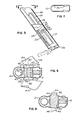
- Figs. 8 through 11 show a variational type of magazine 10a which may be the same as magazine 10 of Figs. 1 through 7 except as to the construction of locking element 39a.
- the magazine body 17a, follower 19a and bottom plate 24a of Figs. 8 through 11 may all be identical with parts 17, 19 and 24 of the first form of the invention, and the follower may be urged upwardly against rounds 15a by a spring such as that shown at 20 in Fig. 3.
- Locking element 39a has a main portion 42a with an outer cylindrical surface 43a which is a close fit within bore 40a formed in follower 19a and centered about a horizontal axis 41a corresponding to axis 41 of the first form of the invention.
- the follower is thus mounted for rotary andaxial movement about axis 41a relative to the follower and the magazine body.
- the locking element 39a has two opposite end portions 44a and 45a which are of the same non-circular cross-sectional configuration about axis 41a as are the portions 44 and 45 of Figs. 1 to 7, with this cross-sectional configuration being defined by parallel surfaces 57a and curved surfaces 58a corresponding to surfaces 57 and 58 of Fig. 4.
- the portion 44a For manually rotating locking element 39a between its holding and released positions, the portion 44a carries at the outside of magazine body 17a and beyond one of the slots 32a in that body an arm or handle portion 46a of locking element 39a which projects transversely of the rotary axis 41 of the locking element and in the released position of the locking element may extend essentially longitudinally of slots 32a as represented in full lines in Fig. 8.
- the arm may have a width x slightly less than the width of the upper narrow portions 33a of slots 32a, and corresponding to the narrow dimension of non-circular portions 44a and 45a of the locking element, with the opposite side surfaces 60 of arm 46a typically lying in the same planes as opposite side surfaces 57a of portions 44a and 45a of the locking element.
- An end surface 61 of arm 46a may be curved in correspondence with and be a continuation of one of the curved surfaces 58a of portion 45a of the locking element, while the arm 46a projects beyond the other curved surface as viewed in Fig. 8.
- the inner surface 62 of arm 46a may be planar and disposed transversely of axis 41a and be received closely adjacent one of the side walls of magazine housing 17a, to enable the arm to be swung about axis 41a between positions such as those shown in full lines and broken lines in Fig. 8.
- the outer surface 63 of arm 46a may be disposed parallel to inner surface 62.
- the second non-circular portion 45a of locking element 39a may be the same as portion 45 of the first form of the invention.
- arm 46a When the magazine 10a of Figs. 8 through 11 is in use within a gun, arm 46a is swung to a position such as that represented in full lines in Fig. 8, in which the non-circular portions 44a and 45a of locking element 46a have their side surfaces 57a disposed parallel to the length of magazine body 17a and its slots 32a, giving the non-circular portions a minimum effective width less than that of the slots enabling those portions to move longitudinally wi.thin the slots as the rounds 15a are successively fired. After the last round has been fired, the magazine is withdrawn from the gun for reloading.
- the locking element 39a is pressed downwardly relative to magazine body 17a by engaging element 39a manually at opposite sides of the housing and pushing it to a position in which non-circular portions 44a and 45a of element 39a are received within the lower enlarged diameter portions 34a of slots 32a, enabling element 39a to be turned through 90° (ninety degrees) by swinging movement of arm 46a to the broken line position of Fig. 8.
- locking element 39a may be actuated to locking condition by axial movement, in a manner similar to that represented in Fig. 6 in connection with the first form of the invention, and by pressing inwardly on portion 44a in Fig. 11 to shift element 39a axially to the broken line position of that figure.
- Such axial movement will lock element 39a and the follower in its lower position without swinging movement of arm 46a between the full line and broken line positions of Fig. 8.
Landscapes
- Engineering & Computer Science (AREA)
- General Engineering & Computer Science (AREA)
- Surgical Instruments (AREA)
- Toys (AREA)
- Optical Head (AREA)
- Valve Device For Special Equipments (AREA)
Applications Claiming Priority (2)
| Application Number | Priority Date | Filing Date | Title |
|---|---|---|---|
| US06/462,920 US4516346A (en) | 1983-02-01 | 1983-02-01 | Magazine for guns |
| US462920 | 1983-02-01 |
Publications (2)
| Publication Number | Publication Date |
|---|---|
| EP0116007A2 true EP0116007A2 (fr) | 1984-08-15 |
| EP0116007A3 EP0116007A3 (fr) | 1985-01-23 |
Family
ID=23838251
Family Applications (1)
| Application Number | Title | Priority Date | Filing Date |
|---|---|---|---|
| EP84630003A Withdrawn EP0116007A3 (fr) | 1983-02-01 | 1984-01-13 | Chargeur pour arme à feu |
Country Status (4)
| Country | Link |
|---|---|
| US (1) | US4516346A (fr) |
| EP (1) | EP0116007A3 (fr) |
| JP (1) | JPS59147998A (fr) |
| DE (1) | DE116007T1 (fr) |
Families Citing this family (13)
| Publication number | Priority date | Publication date | Assignee | Title |
|---|---|---|---|---|
| US5375359A (en) * | 1993-05-27 | 1994-12-27 | Ram-Line, Inc. | Magazine for housing 0.22 rimfire cartridges including truncated cartridges |
| US5566487A (en) * | 1995-09-12 | 1996-10-22 | Smith & Wesson Corp. | Integral butt plate with latch and catch mechanisms for pistol magazine |
| NL1002468C1 (nl) * | 1996-02-28 | 1997-08-29 | Arthur Van Moerkerken | Snellader clip voor pistolen. |
| US6412207B1 (en) | 1998-06-24 | 2002-07-02 | Caleb Clark Crye | Firearm safety and control system |
| US6640480B2 (en) * | 2002-01-23 | 2003-11-04 | Lawrence J. Williams | Gun cleaning kit |
| US7200964B2 (en) * | 2004-02-12 | 2007-04-10 | Gates Craig D | Firearm cartridge clip |
| US8316567B2 (en) * | 2009-11-10 | 2012-11-27 | James Lee Douglas | Easy loading magazine |
| US8720095B2 (en) | 2010-06-18 | 2014-05-13 | Perry Wright | Firearm magazine |
| US9103614B2 (en) * | 2010-11-29 | 2015-08-11 | David Froehle | Quick loading magazine |
| US8713835B1 (en) * | 2013-06-14 | 2014-05-06 | CRMAG Associates | Capacity reducible magazine |
| CN104913682B (zh) * | 2015-05-29 | 2017-04-05 | 重庆建设工业(集团)有限责任公司 | 一种小口径边缘发火枪弹弹匣 |
| CN109175624A (zh) * | 2018-09-26 | 2019-01-11 | 浙江上势自动焊接科技有限公司 | 一种弹匣式螺柱焊枪 |
| US11493293B2 (en) * | 2019-09-25 | 2022-11-08 | Sturm, Ruger & Company, Inc. | Magazine for firearm |
Family Cites Families (9)
| Publication number | Priority date | Publication date | Assignee | Title |
|---|---|---|---|---|
| US1299303A (en) * | 1916-10-16 | 1919-04-01 | William Charles Walter Cowles | Cartridge-magazine for automatic-pistols. |
| US1375322A (en) * | 1920-06-25 | 1921-04-19 | Waldo E Rosebush | Magazine for hand-firearms |
| US2237712A (en) * | 1940-06-04 | 1941-04-08 | Grover F Mullins | Cartridge holder |
| US2655754A (en) * | 1948-05-14 | 1953-10-20 | Brush Clyde Edward | Box magazine for firearms |
| US2620582A (en) * | 1949-04-05 | 1952-12-09 | Earl M Stukas | Firearm magazine |
| CH359063A (de) * | 1957-07-31 | 1961-12-15 | Grob Ferdinand | Munitionsmagazin, insbesondere für automatische Feuerwaffen |
| US3143819A (en) * | 1957-12-06 | 1964-08-11 | Jr Frederick F Stevens | Magazine for pistol |
| US2885811A (en) * | 1958-04-25 | 1959-05-12 | Jr Sherman C Womble | Follower latch for cartridge magazines |
| US4329802A (en) * | 1980-09-10 | 1982-05-18 | Coonan Arms, Inc. | Magazine for large-caliber handguns |
-
1983
- 1983-02-01 US US06/462,920 patent/US4516346A/en not_active Expired - Fee Related
-
1984
- 1984-01-13 DE DE198484630003T patent/DE116007T1/de active Pending
- 1984-01-13 EP EP84630003A patent/EP0116007A3/fr not_active Withdrawn
- 1984-01-30 JP JP59015987A patent/JPS59147998A/ja active Pending
Also Published As
| Publication number | Publication date |
|---|---|
| US4516346A (en) | 1985-05-14 |
| JPS59147998A (ja) | 1984-08-24 |
| EP0116007A3 (fr) | 1985-01-23 |
| DE116007T1 (de) | 1984-12-20 |
Similar Documents
| Publication | Publication Date | Title |
|---|---|---|
| EP0116007A2 (fr) | Chargeur pour arme à feu | |
| US11624574B1 (en) | Apparatus and method for loading pistol magazines | |
| US5417003A (en) | Tool for loading and unloading cartridges from a firearm magazine | |
| CA2416448C (fr) | Accessoire de chargement et dechargement de magasin | |
| US7219462B2 (en) | Receiver assembly for firearm | |
| US6820533B2 (en) | Bolt action rifle | |
| US5099595A (en) | Magazine for a firearm | |
| US3999534A (en) | Gas operated rifle | |
| AU649738B2 (en) | Firearm | |
| US4742634A (en) | Automatic slide guard | |
| DE2905770A1 (de) | Magazinhalter | |
| US4329802A (en) | Magazine for large-caliber handguns | |
| US2981024A (en) | Cartridge loader for a tubular magazine | |
| EP0205661A2 (fr) | Dispositif de chargement pour chargeur d'armes à feu portatives | |
| US4967723A (en) | BB gun loader | |
| US5533291A (en) | Firearm capable of operation with different capacity magazines | |
| WO2023224748A1 (fr) | Accessoire de chargement et de déchargement de chargeur universel | |
| US20030066226A1 (en) | Self-locking firearm bolt action | |
| US4821442A (en) | Center feed magazine for firearms | |
| US2624241A (en) | Gun action | |
| DE102017128911B4 (de) | Selbstladepistole | |
| US2710476A (en) | Magazine latching system | |
| EP0299804A1 (fr) | Stylo | |
| US4342169A (en) | Manually cycled pistol | |
| JPS59224271A (ja) | 火薬作動留め具打込具 |
Legal Events
| Date | Code | Title | Description |
|---|---|---|---|
| PUAI | Public reference made under article 153(3) epc to a published international application that has entered the european phase |
Free format text: ORIGINAL CODE: 0009012 |
|
| AK | Designated contracting states |
Designated state(s): BE DE GB IT |
|
| ITCL | It: translation for ep claims filed |
Representative=s name: RICCARDI SERGIO & CO. |
|
| PUAL | Search report despatched |
Free format text: ORIGINAL CODE: 0009013 |
|
| DET | De: translation of patent claims | ||
| AK | Designated contracting states |
Designated state(s): BE DE GB IT |
|
| STAA | Information on the status of an ep patent application or granted ep patent |
Free format text: STATUS: THE APPLICATION IS DEEMED TO BE WITHDRAWN |
|
| 18D | Application deemed to be withdrawn |
Effective date: 19850924 |
|
| RIN1 | Information on inventor provided before grant (corrected) |
Inventor name: FARRAR, FRANK W. Inventor name: CUPP, CARL J. |