EP0116093A1 - Brillengestell mit mehrfachen brennpunkten - Google Patents
Brillengestell mit mehrfachen brennpunkten Download PDFInfo
- Publication number
- EP0116093A1 EP0116093A1 EP83902441A EP83902441A EP0116093A1 EP 0116093 A1 EP0116093 A1 EP 0116093A1 EP 83902441 A EP83902441 A EP 83902441A EP 83902441 A EP83902441 A EP 83902441A EP 0116093 A1 EP0116093 A1 EP 0116093A1
- Authority
- EP
- European Patent Office
- Prior art keywords
- wire
- nose pad
- spectacle frame
- lens
- frame according
- Prior art date
- Legal status (The legal status is an assumption and is not a legal conclusion. Google has not performed a legal analysis and makes no representation as to the accuracy of the status listed.)
- Withdrawn
Links
- 230000007246 mechanism Effects 0.000 claims abstract description 28
- 230000033001 locomotion Effects 0.000 claims description 12
- 230000008859 change Effects 0.000 claims description 11
- 230000005540 biological transmission Effects 0.000 claims description 3
- 230000006872 improvement Effects 0.000 claims description 3
- 102100034742 Rotatin Human genes 0.000 claims 1
- 101710200213 Rotatin Proteins 0.000 claims 1
- 238000005452 bending Methods 0.000 abstract 2
- 238000006073 displacement reaction Methods 0.000 abstract 1
- DOSMHBDKKKMIEF-UHFFFAOYSA-N 2-[3-(diethylamino)-6-diethylazaniumylidenexanthen-9-yl]-5-[3-[3-[4-(1-methylindol-3-yl)-2,5-dioxopyrrol-3-yl]indol-1-yl]propylsulfamoyl]benzenesulfonate Chemical compound C1=CC(=[N+](CC)CC)C=C2OC3=CC(N(CC)CC)=CC=C3C(C=3C(=CC(=CC=3)S(=O)(=O)NCCCN3C4=CC=CC=C4C(C=4C(NC(=O)C=4C=4C5=CC=CC=C5N(C)C=4)=O)=C3)S([O-])(=O)=O)=C21 DOSMHBDKKKMIEF-UHFFFAOYSA-N 0.000 description 7
- 230000006835 compression Effects 0.000 description 4
- 238000007906 compression Methods 0.000 description 4
- 230000004048 modification Effects 0.000 description 3
- 238000012986 modification Methods 0.000 description 3
- 208000003464 asthenopia Diseases 0.000 description 2
- 230000008901 benefit Effects 0.000 description 2
- 238000010276 construction Methods 0.000 description 2
- 239000011435 rock Substances 0.000 description 2
- 229910000831 Steel Inorganic materials 0.000 description 1
- 230000002301 combined effect Effects 0.000 description 1
- 230000000052 comparative effect Effects 0.000 description 1
- 230000000694 effects Effects 0.000 description 1
- 210000000887 face Anatomy 0.000 description 1
- 230000003287 optical effect Effects 0.000 description 1
- 239000007779 soft material Substances 0.000 description 1
- 239000010959 steel Substances 0.000 description 1
- 230000007704 transition Effects 0.000 description 1
Images



Classifications
-
- G—PHYSICS
- G02—OPTICS
- G02C—SPECTACLES; SUNGLASSES OR GOGGLES INSOFAR AS THEY HAVE THE SAME FEATURES AS SPECTACLES; CONTACT LENSES
- G02C5/00—Constructions of non-optical parts
- G02C5/22—Hinges
- G02C5/2263—Composite hinges, e.g. for varying the inclination of the lenses
-
- G—PHYSICS
- G02—OPTICS
- G02C—SPECTACLES; SUNGLASSES OR GOGGLES INSOFAR AS THEY HAVE THE SAME FEATURES AS SPECTACLES; CONTACT LENSES
- G02C5/00—Constructions of non-optical parts
-
- G—PHYSICS
- G02—OPTICS
- G02C—SPECTACLES; SUNGLASSES OR GOGGLES INSOFAR AS THEY HAVE THE SAME FEATURES AS SPECTACLES; CONTACT LENSES
- G02C5/00—Constructions of non-optical parts
- G02C5/02—Bridges; Browbars; Intermediate bars
- G02C5/10—Intermediate bars or bars between bridge and side-members
-
- G—PHYSICS
- G02—OPTICS
- G02C—SPECTACLES; SUNGLASSES OR GOGGLES INSOFAR AS THEY HAVE THE SAME FEATURES AS SPECTACLES; CONTACT LENSES
- G02C5/00—Constructions of non-optical parts
- G02C5/12—Nose pads; Nose-engaging surfaces of bridges or rims
- G02C5/122—Nose pads; Nose-engaging surfaces of bridges or rims with adjustable means
- G02C5/124—Nose pads; Nose-engaging surfaces of bridges or rims with adjustable means for vertically varying the position of the lenses
-
- G—PHYSICS
- G02—OPTICS
- G02C—SPECTACLES; SUNGLASSES OR GOGGLES INSOFAR AS THEY HAVE THE SAME FEATURES AS SPECTACLES; CONTACT LENSES
- G02C2200/00—Generic mechanical aspects applicable to one or more of the groups G02C1/00 - G02C5/00 and G02C9/00 - G02C13/00 and their subgroups
- G02C2200/18—Adjustment ridges or notches
Definitions
- This invention relates to improvements in a multifocal spectacle frame of the type in which the spectacle frame can, by a simple operation, be moved vertically and also tilted to change the angle of inclination of the spectacle frame so that the spectacles can be used in an optically optimum condition and worn with comfort whichever segment of a lens is used.
- multifocal spectacle frames of the type in which side pieces are pivoted up and down in a vertical plane and nose pieces moved up and down to move the spectacle lenses vertically and change the angle of inclination of the spectacle lenses, relative to the normal line of vision (referred to as the horizontal line of vision when looking into the distance) of the user.
- Applications have been filed on these multifocal spectacle frames (Japanese Patent Application Nos. 55-128629, 56-59000, 56-124803, Japanese Utility Model Application Nos. 56-118374, 56-138292 and International Application No. PCT/JP82/00025, etc.).
- these multifocal spectacle frames are highly effective in that the spectacles can be used in an optically optimum condition and worn with comfort whichever segment of a lens is used.
- two separate operations must be performed, namely an operation of extending the side pieces straight out or moving them up and down, and an operation of moving the nose pads up and down or of rotating the nose pads.
- the spectacle frames are disadvantageous in that an individual not accustomed to using them will find these operations difficult to perform.
- the side pieces can be moved up and down with comparative ease, a drawback is that some difficulty is involved in operating the nose pads.
- the present invention has as its object to provide a multifocal spectacle frame which eliminates the aforesaid shortcomings possessed by the multifocal spectacle frames disclosed by the foregoing applications of the present applicant, wherein the nose pads can be operated automatically when the side pieces are moved up and down, thereby vastly simplifying the operation of the spectacles.
- Another object of the present invention is to provide a multifocal spectacle frame which, despite a very simple structure, is capable of being operated reliably and used for many years.
- a further object of the present invention is to provide a multifocal spectacle frame in which vertical movement of the side pieces and movement of the nose pads can be operatively associated without detracting from the exterior design of the overall spectacle frame.
- the present invention relates to a multifocal spectacle frame comprising a pair of rightside and leftside lens rims for mounting multifocal lenses, a bridge for interconnecting the leftside and rightside lens rims, a nose pad for supporting the inner side of each of the rightside and leftside lens rims on the sides of the nose, a support attached to the outer side of each of the rightside and leftside lens rims, a side piece attached to the support so as to be foldable upward and downward through a predetermined angle, a folding mechanism for attaching the side piece to the support so as to be foldable upward and downward through a predetermined angle, and a level adjusting mechanism for moving an abutting surface of the nose pad upward and down- word in order to change the relative height of the lens rims with respect to the normal line of vision, the abutting surface being moved up and down by moving the nose pad vertically or by rotating the nose pad, the improvement comprising transmission means for transmitting the relative motion of the side piece, with respect to the support, to
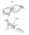
- Fig. 1 is a perspective view illustrating a first embodiment in which the present invention is applied to bifocal spectacles.
- the character A designates the main body of the spectacle frame, which comprises a pair of leftside and rightside lens rims 1, 1, and a bridge 2 linking the leftside and rightside lens rims 1, 1 at the portions slightly above center.
- Fitted into the lens rims 1, 1 are respective bifocal lenses 3, 3 in which close-up lens segments 5, 5 are formed integral with distance lens segments 4, 4 at the lower part thereof.
- Conventional bifocal spectacles are substantially the same in construction.
- columnar mounting legs 6, 6 Affixed to the inner sides of the lens rims 1, 1 in confronting relation are columnar mounting legs 6, 6 each having a vertically extending through-hole.
- the vertically extending through-holes have a rectangular cross section.
- These rectangular holes receive respective slide rods 7, 7 of rectangular columnar shape which are capable of being moved up and down within the holes.
- Nose pads 9, 9 are attached to the lower ends of the slide rods 7, 7 via bent adjusting rods 8, 8.
- Wire-like bodies 10, 10 are attached at one end thereof to the upper ends of the slide rods 7, 7.
- Slender tubes 11, 11 are attached to the upper sides of the lens rims 1, 1 and extend along the rims.
- the wire-like bodies 10, 10, which are passed through the tubes 11, 11, are connected at one end to the upper end of the respective slide rods 7, 7, and at the other end to the distal end of respective rotating bodies 12, 12.
- the front ends of supports 13, 13 are rigidly attached to the outer sides of the lens rims 1, 1, and side pieces 14, 14 are so attached to the supports 13, 13 as to be capable of pivotal movement both horizontally and vertically.
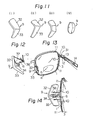
- the portions composed of the supports 13, 13 and side pieces 14, 14 will be described with reference to the perspective, exploded view of Fig. 2.
- the rear edge portion of the support 13 is formed into an arcuate shape.
- a support piece 15 having a substantially C-shaped cross section is secured near the rear end of the support 13 on the inner side thereof. Holes in positional alignment are drilled through the support 13 and support piece 15, and the hole on the side of the support 15 has female threads.
- the rotating body 12 having a hole which will be in positional alignment with the holes in the support 13 and support piece 15, is fitted into the support piece 15, and a screw 16 is passed through these holes and screwed into the hole of the support piece 15, whereby the rotating body 12 is capable of being rotated about the screw 16.
- the rear end of the rotating body 12 is formed to include two vertically spaced rings 17, 17, one above the other.
- the hole in the lower ring 17 has female threads.
- the other end of the wire-like body 10 is affixed to the front end of the rotating body 12, as mentioned above.
- a swivelling joint 18 having a ring 19 at its distal end is affixed near the front end of the side piece 14 on the inner side thereof.
- the edge at the front end of the side piece 14 is formed into an arcuate concave to match the arcuate shape of the rear edge of the support 13.
- the ring 19 of the swivelling joint 18 is inserted between the rings 17, 17 of the rotating body 12, in which state a screw 20 is passed through the ring 19 from the hole in the upper ring 17 and is screwed into the hole in the lower ring 17.
- the side piece 14 is so attached as to be foldable inwardly about the fulcrum of the screw 20.
- the arrangement is such that, when the side piece 14 is swung outwardly in the horizontal direction to be fully extended, the front edge of the side piece 14 abuts against the rear edge of the support 13 to bring the side piece to a stop.
- Fig. 1 shows the side pieces 14, 14 extended straight out by being pivoted in the vertical direction, and shows the nose pads 9, 9 in their upper position.
- the main body A of the spectacle frames is supported in a lowered attitude relative to the front of the wearer's face, and the long distance lens segments 4, 4 are brought substantially to the center of the normal line of vision.
- the normal line of vision for distant viewing and the plane of the lenses meet at substantially right angles, this being the optimum optical condition for such viewing.
- the close-up lens segments 5, 5 are situated a good deal below the normal line of vision for distant viewing and are not an impedement to such viewing. Therefore, this eliminates such drawbacks as the boundary between the long-distance lens segments 4, 4 and close-up lens segments 5, 5 coming into view, as well as a blurring at one's feet, thus enabling the spectacles to be worn with comfort.
- This pushing down of the slide rods 7, 7 is performed by the wire-like body 10 itself when the wire-like body is a incompressible wire member such as steel, or with the aid of a return spring, not shown, provided at a prescribed location.
- the main body A is raised relative to the wearer's face and is supported on the nose in a forwardly tilted state.
- the downward pivoting of the side pieces 14, 14 with respect to the main body A not only tilts the main body A forwardly, but also brings the close-up lens segments 5, 5 slightly nearer to the eyes, and lifts the main body A relative to the wearer's face. Therefore, the combined effect of the downward pivoting of the side pieces 14, 14 relative to the main body A and the support of the nose pads 9, 9 at the lower position causes the main body A to be supported on the nose in a raised attitude.
- FIG. 3 A small shaded area is shown in Fig. 3 to represent the area where the face of the nose pad 9 abuts against the wearer's nose.
- the arrangement is such that the faces of the nose pads 9, 9 abut against substantially the same points on the nose when the main body A is supported at both the upper and lower positions.
- the close-up lens segments 5, 5 affixed thereto also are tilted slightly forward and raised to bring them close to the center of the field of vision and close to the eyes.
- the close-up lens segments 5, 5 are used when viewing an object up close, at which time the line of vision is directed downwardly. Owing to the slight forward tilt of the main body A, therefore, the lenses 3, 3 are inclined to form approximate right angles with the line of vision. Also, since the close-up lens segments 5, 5 are brought close to the center of the field of vision and are substantially perpendicular to the line of vision, eye strain is minimized.
- the angle of inclination of the spectacles is medically ideal, being 5 to 10° when the long-distance lens segments are used, an about 20° when the close-up lens segmenets are used. Further, since the close-up lens segments 5, 5 are brought close to the eyes, an additional advantage is that the field of vision can be widened.
- the nose pads 9, 9 are adapted to slide up and down.
- the nose pads 9, 9 are adapted to be move up and down by being so swivelled.
- the mounting legs 6, 6 in the second embodiment have an overall plate shape and an arcuate distal end.
- the nose pads 9, 9 are attached to these arcuate front ends in such a manner that they can be swivelled up and down.
- FIG. 5 is a perspective, exploded view, partially cut away, of the portion where the mounting leg 6 and nose pads 9 are attached.
- the mounting leg 6 is formed at its distal end with a semicircular slot, and with a slot, also of semicircular configuration but of smaller radius, cut in the mounting leg opposite to the other semicircular slot.
- Two stepped portions 21 and 22 are formed between the two slots.
- the mounting leg 6 is provided with a horizontally extending hole 23 for receiving a screw passed therethrough.
- the pad arm 24 has a small ring 25 attached to its upper surface, and a swivel 26 attached to end portion.
- the swivel 26 has the configuration of a disk with a sector-shaped portion integrally attached to its outer periphery, and is sized to be closely encased in the slots of the mounting leg 6. Stepped portions 27 and 28 are defined on the front and back sides of the sector-shaped portion, and the central portion of the disk is provided with a hole 29 for receiving the screw which will be passed therethrough.
- the swivel 26 is fit into the slots of the mounting leg 6 and the hole 23 in the mounting leg 6 is aligned with the hole 29 in the swivel 26, after which the screw 30 is inserted and tightened by screwing to attach the nose pad 9 to the mounting leg 6 via the pad arm 24 in such a manner that the nose pad can be swivelled (shown in Fig. 4).
- the inner ends of the wire-like bodies 10, 10 are connected to the rings 25, 25 of the pad arms 24, 24.
- the wire-like bodies 10, 10 exert an upward pulling force upon the nose pads 9, 9.
- the stepped portions 27, 27 of the swivel 26, 26 abut against the stepped portions 21, 21 of the mounting legs 6, 6.
- the nose pads 9, 9 are pushed downward, so that the stepped portions 28, 28 of the swivels 26, 26 abut against the stepped portions 22, 22 of the mounting legs 6, 6.
- the arrangement is such that the spacing g between the righthand and lefthand nose pads 9, 9 when they are swivelled to the upward position is approximately equal to the spacing Q' when they are swivelled to the downward position.
- the second embodiment is used in the manner shown in Fig. 7.
- the side pieces 14, 14 are extended straight out with respect to the supports 13, 13, whereby the nose pads 9, 9 are swivelled upward.
- the main body A is supported at a low position on the wearer's nose.
- the main body A is grasped by one's hand and is merely tilted forwardly while the spectacles remain being worn.
- the side pieces 14, 14 fold relative to the supports 13, 13 and, at the same time, the nose pads 9, 9 are swivelled downward, as shown in Fig. 7(ii).
- Abutting areas b, b, where the nose pads 9, 9 contact the nose when the spectables are worn in this manner, are slightly above abutting areas a, a shown in Fig. 7(i). Specifically, as shown in Fig.
- the distance between ear and nose pad is reduced owing to the folding of the side pieces 14, 14 with respect to the supports 13, 13, and the nose pads 9, 9 are swivelled to the lower position, whereby the main body A is supported in a lifted condition. Further, since the main body A is supported in a forwardly tilted attitude, the close-up lens segements 5, 5 affixed thereto also are tilted forwardly and raised. This brings the close-up lens segments close to the center of the line of vision and close to the eyes.
- Regulation of the vertical distance travelled by the main body A is achieved by adjusting the bend angle of the pad arms 24, 24 to take account of the difference between individuals, adopting a setting such that the spacing between the nose pads 9, 9 in the upwardly and downwardly rotated positions will differ,
- rocking pieces 31, 31 are attached for rocking motion to the inner sides of the supports 13, 13 near the forward ends thereof by means of respective pins.
- the outer end of each rocking piece 31, 31 is provided with a drilled hole into which the tip of the respective rotating body 12, 12, formed to have a slender configuration, is inserted.
- the outer ends of the wire-like bodies 10, 10 are attached to the inner sides of the rocking pieces 31, 31.
- the nose pad 9 which is bent at a point along its length into a slightly V-shaped configuration, is composed of an upwardly situated upper abutting surface 32, and a downwardly situated lower abutting surface 33.
- the nose pad 9 is rotatably attached to the distal end of the mounting leg 6 by a pin 34, and is provided with a compression spring 35 on the side of its upper abutting surface 32.
- a ring 36 is attached to the mounting leg 6.
- the wire-like body 10 is passed through the ring 6 and extended and has its inner end connected to the upper end of the nose pad 9.
- the operation of the third embodiment is as shown in Fig. 10.
- the spectacles are worn with the side pieces 14, 14 extended straight out with respect to the supports 13, 13, the upper abutting surfaces 32, 32 of the nose pads 9, 9 contact the abutting surfaces a, a of the wearer's nose, with the result that the main body A is supported in a lowered attitude.
- the nose pad 9 is bent at a point along its length into a slightly V-shaped configuration, and the surface thereof is formed to include an upwardly situated upper abutting surface 32 and a downwardly situated lower abutting surface 33.
- the object of such a surface is, first, to make it possible to support the main body A in two different conditions, namely in an uplifted condition and a lowered condition, and second, to compensate for a change in the angle of contact with the contact surfaces on the sides of the wearer's nose by rotation of the nose pad 9 when the main body A is moved up and down.
- the upper abutting surface 32 and lower abutting surface 33 are of approximately the same width.
- the upper abutting surface 32 can be made wider than the lower abutting surface 33, or the opposite arrangement can be adopted, as shown in Fig. 11(ii).
- Fig. 11(iii) illustrates a nose pad used in a trifocal spectacle frame, the nose pad having three abutting surfaces.
- Fig. 11(iv) illustrates a nose pad used in a spectacle frame for three of more foci, the nose pad having a substantially spherical surface. In the views of Fig. 11, only the leftside nose pad, as viewed from the wearer, has been depicted. The rightside nose pad is symmetrically opposite in configuration to the leftside one,
- the fifth embodiment is a modification of the third embodiment, and has two tubes 11, one disposed along the upper side and the other disposed along the lower side of the lens rims 1, 1.
- the wire-like bodies 10, 10 are passed through the interior of each tube 11.
- the outer end of each of the wire-like bodies 10, 10 of each pair is connected to the tip of the corresponding rocking bodies 31, 31 rockably attached to the supports 13, 13.
- the inner end of each of the wire-like bodies 10, 10 of each pair is connected to corresponding upper and lower rings 38, 38, which are provided on the back surface of the nose pads 9, 9.
- one of the upper and lower wire-like bodies 10, 10 pulls and rocks the nose pads 9, 9 in a predetermined direction.
- This embodiment is advantageous in that the prescribed motion can be transmitted with good reliability even if the wire-like bodies 10, 10 consist of a soft material.
- the sixth embodiment is a modification of the fifth embodiment depicted in Figs. 13 and 14.
- the inner ends of the wire-like bodies 10, 10 extending through the tubes 11, which are provided along the upper and lower sides of the lens rims 1, 1, are connected to the upper and lower ends, respectively, of a slide member 41 accommodated interiorly of a mounting leg 40 so as to be slidable up and down.
- a rack 44 meshing with a pinion 43 of a swivel 42 Formed on the slide member 41 is a rack 44 meshing with a pinion 43 of a swivel 42.
- the construction of the mounting leg 40 and swivel 42 is similar to that of the mounting leg 6 and swivel 26 in Fig. 5.
- the portions corresponding to these similar structural elements are not designated by reference numerals.
- a mechanism is available wherein the mounting legs 6, 6 are attached to the inner sides of the respective lens rims 1, 1 via slide members attached to the lens rims 1, 1 so as to be slidable up and down, and the inner ends of the wire-like bodies 10, 10 extending through the tubes 11, which are provided along the upper and lower sides of the lens rims 1, 1, are attached to the swivel 26 or to the nose pad arm 24 affixed to the swivel 26.
- This mechanism is advantageous in that a portion of the upward and downward movement of the nose pads 9, 9 is born by the slide members attached to the inner sides of the lens rims 1, 1, the amount of upward and downward movement being enlarged while fully compensating for the change in the angle of contact which the nose pads make with the contact surfaces on the sides of the wearer's nose.
- a seventh embodiment of the present invention will now be described in conjunction with Fig. 16.
- a single tube 11 is provided for each lens rim 1, and two of the wire-like bodies 10 are passed through each tube.
- the outer end of each of these wire-like bodies 10, 10 is attached to the tip of the rotating body 12.
- One of the wire-like bodies 10 is passed through tube 11 together with the other wire-like body 10 after being looped around a roller 39 attached to the lens rim 1.
- one of the wire-like bodies 10 will be pulled regardless of the direction in which the rotating body 12 is rotated, providing the same effects as the fifth embodiment.
- the tube 11 is used for receiving the wire-like body 10.
- the lens rim 1 can be made hollow and the wire-like body 10 passed through the hollow portion, or the lens rim 1 can be provided with a groove and the wire-like body 10 laid within the groove.
- folding mechanism has been disclosed wherein the side pieces 14 are extended straight out and pivoted up and down with respect to the supports 13, 13.
- options other than this folding mechanism can be adopted.
- various arrangements other than those illustrated can be adopted for the mechanisms that slide or rotate the nose pad 9. It should be understood that, although the above description has been made in reference to bifocal spectacles, this invention is also applicable to other types of spectacles having three or more foci.
- the side piece 14 which is provided on the outer side of each of the lens rims 1, is suitably tilted with respect to the lens rim 1 via a folding mechanism for extending the side piece 14 straight out, or for rotating the side piece up and down, with respect to the support 13.
- a folding mechanism for extending the side piece 14 straight out, or for rotating the side piece up and down, with respect to the support 13.
- the multifocal spectacle frame according to the present invention merely selecting a suitable folding angle for the side piece 14 relative to the support 13 enables a desired lens segment, from among those in the multifocal lens fitted in the lens rim 1, to be brought to a level for easiest use.
- the lends segment used is employed at an optically ideal angle, eye strain can be prevented.
Landscapes
- Physics & Mathematics (AREA)
- Health & Medical Sciences (AREA)
- General Physics & Mathematics (AREA)
- Ophthalmology & Optometry (AREA)
- Optics & Photonics (AREA)
- Eyeglasses (AREA)
Applications Claiming Priority (2)
| Application Number | Priority Date | Filing Date | Title |
|---|---|---|---|
| JP57132986A JPS5924824A (ja) | 1982-07-31 | 1982-07-31 | 多焦点用眼鏡枠 |
| JP132986/82 | 1982-07-31 |
Publications (2)
| Publication Number | Publication Date |
|---|---|
| EP0116093A1 true EP0116093A1 (de) | 1984-08-22 |
| EP0116093A4 EP0116093A4 (de) | 1985-02-28 |
Family
ID=15094105
Family Applications (1)
| Application Number | Title | Priority Date | Filing Date |
|---|---|---|---|
| EP19830902441 Withdrawn EP0116093A4 (de) | 1982-07-31 | 1983-07-27 | Brillengestell mit mehrfachen brennpunkten. |
Country Status (6)
| Country | Link |
|---|---|
| EP (1) | EP0116093A4 (de) |
| JP (1) | JPS5924824A (de) |
| KR (1) | KR840005562A (de) |
| DK (1) | DK26484A (de) |
| IT (1) | IT1168810B (de) |
| WO (1) | WO1984000618A1 (de) |
Cited By (16)
| Publication number | Priority date | Publication date | Assignee | Title |
|---|---|---|---|---|
| EP0406245A4 (en) * | 1988-01-25 | 1991-04-10 | Gregory, John, R | Vertical plane adjusting mechanism for eyeglasses |
| GB2239958A (en) * | 1990-08-31 | 1991-07-17 | Sam Joel Mendel | Spectacle frame having adjustable nose members |
| EP0691561A4 (de) * | 1994-01-27 | 1996-05-08 | Masunaga Optical Mfg Co Ltd | Brillengestell vom typ mit austauschbaren nasenauflageplättchen |
| WO1998033086A1 (en) * | 1997-01-29 | 1998-07-30 | Oakley, Inc. | Interchangeable nosepiece system |
| WO2000026714A1 (en) * | 1998-10-30 | 2000-05-11 | Agilent Technologies, Inc. | Articulated nose bridge for head mounted display |
| EP1168036A1 (de) * | 2000-06-21 | 2002-01-02 | Youchi Kaihatsu Co. Ltd | Einstellbares Brillengestell |
| FR2829243A1 (fr) * | 2001-08-31 | 2003-03-07 | Schen Yih Lin | Lunettes a accommodation automatique |
| US6929364B1 (en) | 1995-04-04 | 2005-08-16 | Oakley, Inc. | Contoured metal eyeglass frames |
| US7448750B2 (en) | 2006-09-22 | 2008-11-11 | Oakley, Inc. | Quadrilateral lens |
| EP1992981A1 (de) * | 2007-05-15 | 2008-11-19 | Washin Optical Co., Limited | Einstellmechanismus für Brillenbügel |
| WO2009014482A1 (en) * | 2007-07-25 | 2009-01-29 | Liselott Grip | Nose pad device for adjustment of a nose pad of a spectacle frame. |
| US7726810B2 (en) | 2007-08-17 | 2010-06-01 | Politzer Thomas A | Tilted prism for the treatment of cyclo deviation |
| WO2010077496A3 (en) * | 2008-12-08 | 2010-10-07 | Alexsey Mazurenko | Magnification viewer with loupe mounting assembly |
| WO2012078913A3 (en) * | 2010-12-08 | 2012-11-08 | Vision Jeannie, Llc | Adjustable eyewear, lenses, and frames |
| US8721070B2 (en) | 2010-12-08 | 2014-05-13 | Refine Focus, Llc | Translating multifocal eyeglass lenses |
| EP3511766A4 (de) * | 2016-09-07 | 2020-07-08 | Norio Seki | Rahmen in form einer zweistärkenbrille |
Families Citing this family (6)
| Publication number | Priority date | Publication date | Assignee | Title |
|---|---|---|---|---|
| JPS6138925A (ja) * | 1984-07-31 | 1986-02-25 | Akiyoshi Kasai | レンズ枠を動かせる累進多焦点レンズ用眼鏡枠 |
| DE3529613A1 (de) * | 1984-08-20 | 1986-02-27 | Robert Ellentuch Silver Spring Fischell, Md. | Versteifungszylinder fuer ein aufblasbares peniserektionsgeraet |
| US4671261A (en) * | 1986-01-24 | 1987-06-09 | Fischell Robert | Penile erection device with valving in the penile cylinder |
| US4895139A (en) * | 1988-08-29 | 1990-01-23 | American Medical Systems, Inc. | Inflatable penile prosthesis with bend release valve |
| US5048510A (en) * | 1988-08-29 | 1991-09-17 | American Medical Systems, Inc. | Inflatable penile prosthesis with satellite reservoir |
| JPH0329919U (de) * | 1989-07-31 | 1991-03-25 |
Family Cites Families (7)
| Publication number | Priority date | Publication date | Assignee | Title |
|---|---|---|---|---|
| DE702214C (de) * | 1937-11-22 | 1941-02-01 | Alexander Cserep | Fassungsbrille fuer Bifokalglaeser |
| DE1215956B (de) * | 1964-05-04 | 1966-05-05 | Peter Dueren | Einhandbrille mit zwei Brillenbuegeln |
| IT7911669V0 (it) * | 1979-05-25 | 1979-05-25 | Fortini Umberto | Frizionatura per l'articolazione di aste per occhiali |
| JPS5918429Y2 (ja) * | 1980-07-30 | 1984-05-28 | 亨 根岸 | 眼鏡の鼻当て |
| JPS5921003B2 (ja) * | 1980-09-18 | 1984-05-17 | 亨 根岸 | 多焦点用眼鏡枠 |
| JPS5798425U (de) * | 1980-12-10 | 1982-06-17 | ||
| AU551217B2 (en) * | 1981-04-17 | 1986-04-17 | Negishi, Tohru | Spectacle frame for multi-focus spectacles |
-
1982
- 1982-07-31 JP JP57132986A patent/JPS5924824A/ja active Granted
-
1983
- 1983-07-27 EP EP19830902441 patent/EP0116093A4/de not_active Withdrawn
- 1983-07-27 WO PCT/JP1983/000242 patent/WO1984000618A1/ja not_active Ceased
- 1983-07-29 IT IT67822/83A patent/IT1168810B/it active
- 1983-08-01 KR KR1019830003595A patent/KR840005562A/ko not_active Withdrawn
-
1984
- 1984-01-20 DK DK26484A patent/DK26484A/da not_active Application Discontinuation
Cited By (24)
| Publication number | Priority date | Publication date | Assignee | Title |
|---|---|---|---|---|
| EP0406245A4 (en) * | 1988-01-25 | 1991-04-10 | Gregory, John, R | Vertical plane adjusting mechanism for eyeglasses |
| GB2239958A (en) * | 1990-08-31 | 1991-07-17 | Sam Joel Mendel | Spectacle frame having adjustable nose members |
| GB2239958B (en) * | 1990-08-31 | 1992-03-04 | Sam Joel Mendel | Height adjustable spectacles |
| EP0691561A4 (de) * | 1994-01-27 | 1996-05-08 | Masunaga Optical Mfg Co Ltd | Brillengestell vom typ mit austauschbaren nasenauflageplättchen |
| US6929364B1 (en) | 1995-04-04 | 2005-08-16 | Oakley, Inc. | Contoured metal eyeglass frames |
| US7686449B2 (en) | 1995-04-04 | 2010-03-30 | Oakley, Inc. | Eyewear retention system and method |
| US7222959B2 (en) | 1995-04-04 | 2007-05-29 | Oakley, Inc. | Contoured metal eyeglass frames |
| WO1998033086A1 (en) * | 1997-01-29 | 1998-07-30 | Oakley, Inc. | Interchangeable nosepiece system |
| US6056399A (en) * | 1997-01-29 | 2000-05-02 | Oakley, Inc. | Interchangeable nosepiece system |
| US6250756B1 (en) | 1997-01-29 | 2001-06-26 | Oakley, Inc. | Biased eyeglass frames |
| WO2000026714A1 (en) * | 1998-10-30 | 2000-05-11 | Agilent Technologies, Inc. | Articulated nose bridge for head mounted display |
| US6520636B2 (en) | 2000-06-21 | 2003-02-18 | Youchi Kaihatsu Co., Ltd. | Nosepiece assembly for an adjustable eyeglass frame |
| EP1168036A1 (de) * | 2000-06-21 | 2002-01-02 | Youchi Kaihatsu Co. Ltd | Einstellbares Brillengestell |
| FR2829243A1 (fr) * | 2001-08-31 | 2003-03-07 | Schen Yih Lin | Lunettes a accommodation automatique |
| US7448750B2 (en) | 2006-09-22 | 2008-11-11 | Oakley, Inc. | Quadrilateral lens |
| EP1992981A1 (de) * | 2007-05-15 | 2008-11-19 | Washin Optical Co., Limited | Einstellmechanismus für Brillenbügel |
| WO2009014482A1 (en) * | 2007-07-25 | 2009-01-29 | Liselott Grip | Nose pad device for adjustment of a nose pad of a spectacle frame. |
| US7726810B2 (en) | 2007-08-17 | 2010-06-01 | Politzer Thomas A | Tilted prism for the treatment of cyclo deviation |
| WO2010077496A3 (en) * | 2008-12-08 | 2010-10-07 | Alexsey Mazurenko | Magnification viewer with loupe mounting assembly |
| WO2012078913A3 (en) * | 2010-12-08 | 2012-11-08 | Vision Jeannie, Llc | Adjustable eyewear, lenses, and frames |
| US8721070B2 (en) | 2010-12-08 | 2014-05-13 | Refine Focus, Llc | Translating multifocal eyeglass lenses |
| EP3079005A1 (de) * | 2010-12-08 | 2016-10-12 | Essilor International | Einstellbare brillen, linsen und gestelle |
| EP3511766A4 (de) * | 2016-09-07 | 2020-07-08 | Norio Seki | Rahmen in form einer zweistärkenbrille |
| US11119336B2 (en) | 2016-09-07 | 2021-09-14 | Norio Seki | Bifocal glasses-shaped frame |
Also Published As
| Publication number | Publication date |
|---|---|
| IT8367822A0 (it) | 1983-07-29 |
| DK26484A (da) | 1984-02-16 |
| EP0116093A4 (de) | 1985-02-28 |
| JPS5924824A (ja) | 1984-02-08 |
| KR840005562A (ko) | 1984-11-14 |
| WO1984000618A1 (fr) | 1984-02-16 |
| JPH0259444B2 (de) | 1990-12-12 |
| DK26484D0 (da) | 1984-01-20 |
| IT1168810B (it) | 1987-05-20 |
Similar Documents
| Publication | Publication Date | Title |
|---|---|---|
| CA1179876A (en) | Spectacle frame for multifocal lenses | |
| JPH0259444B2 (de) | ||
| US4861151A (en) | Frame for multifocal spectacles | |
| US10838229B2 (en) | Bifocal glasses-shaped frame | |
| KR20000011478A (ko) | 다중촛점렌즈를갖춘안경테용일체형수직평면조절기구 | |
| US2350386A (en) | Eyeglasses | |
| JP7080116B2 (ja) | アイウエアおよびテンプル | |
| CN219016725U (zh) | 一种具有双联动支撑臂机构的防近视阅读仪 | |
| CN109690390B (zh) | 远近两用眼镜状的框架 | |
| US6183080B1 (en) | Integral vertical plane adjusting mechanism for an eyeglass frame with multifocal lenses | |
| KR102562601B1 (ko) | 길이조절이 가능한 코패드를 구비한 안경 | |
| JPS5921003B2 (ja) | 多焦点用眼鏡枠 | |
| CN211123487U (zh) | 结构改进型ar眼镜 | |
| CN214151275U (zh) | 一种免低头可调眼镜 | |
| JPS6222131B2 (de) | ||
| WO2012114362A1 (en) | Multifocal frames | |
| CN218350583U (zh) | 反射式观测设备 | |
| JPH028255Y2 (de) | ||
| CN218767642U (zh) | 设有耳后卡位机构的眼镜架 | |
| CN216210262U (zh) | 一种全方位可调节式防近视阅读放大仪 | |
| CN218917827U (zh) | 一种镜框及可后视眼镜 | |
| CN222259743U (zh) | 一种可调节眼镜 | |
| CN223022482U (zh) | 角度可调式镜腿及眼镜 | |
| CN215729131U (zh) | 一种渐进多焦眼镜 | |
| EP2176701A1 (de) | Nasenbügelvorrichtung zur anpassung des nasenbügels einer brillenfassung |
Legal Events
| Date | Code | Title | Description |
|---|---|---|---|
| PUAI | Public reference made under article 153(3) epc to a published international application that has entered the european phase |
Free format text: ORIGINAL CODE: 0009012 |
|
| 17P | Request for examination filed |
Effective date: 19840424 |
|
| AK | Designated contracting states |
Designated state(s): AT CH DE FR LI NL SE |
|
| STAA | Information on the status of an ep patent application or granted ep patent |
Free format text: STATUS: THE APPLICATION HAS BEEN WITHDRAWN |
|
| 18W | Application withdrawn |
Withdrawal date: 19841206 |