EP0116102A2 - Appareil pour l'assistance aux travaux de sauvetage spécialement dans des bâtiments dits gratte-ciels - Google Patents
Appareil pour l'assistance aux travaux de sauvetage spécialement dans des bâtiments dits gratte-ciels Download PDFInfo
- Publication number
- EP0116102A2 EP0116102A2 EP83101218A EP83101218A EP0116102A2 EP 0116102 A2 EP0116102 A2 EP 0116102A2 EP 83101218 A EP83101218 A EP 83101218A EP 83101218 A EP83101218 A EP 83101218A EP 0116102 A2 EP0116102 A2 EP 0116102A2
- Authority
- EP
- European Patent Office
- Prior art keywords
- cable
- boom
- drums
- cable drums
- roller
- Prior art date
- Legal status (The legal status is an assumption and is not a legal conclusion. Google has not performed a legal analysis and makes no representation as to the accuracy of the status listed.)
- Withdrawn
Links
- 230000001681 protective effect Effects 0.000 claims description 8
- KAATUXNTWXVJKI-UHFFFAOYSA-N cypermethrin Chemical compound CC1(C)C(C=C(Cl)Cl)C1C(=O)OC(C#N)C1=CC=CC(OC=2C=CC=CC=2)=C1 KAATUXNTWXVJKI-UHFFFAOYSA-N 0.000 claims description 7
- 238000004804 winding Methods 0.000 claims description 3
- 230000001360 synchronised effect Effects 0.000 claims 1
- 230000005540 biological transmission Effects 0.000 description 1
- 238000013016 damping Methods 0.000 description 1
- 238000009434 installation Methods 0.000 description 1
- 230000002787 reinforcement Effects 0.000 description 1
Images

Classifications
-
- A—HUMAN NECESSITIES
- A62—LIFE-SAVING; FIRE-FIGHTING
- A62B—DEVICES, APPARATUS OR METHODS FOR LIFE-SAVING
- A62B1/00—Devices for lowering persons from buildings or the like
- A62B1/06—Devices for lowering persons from buildings or the like by making use of rope-lowering devices
- A62B1/08—Devices for lowering persons from buildings or the like by making use of rope-lowering devices with brake mechanisms for the winches or pulleys
- A62B1/10—Devices for lowering persons from buildings or the like by making use of rope-lowering devices with brake mechanisms for the winches or pulleys mechanically operated
-
- A—HUMAN NECESSITIES
- A62—LIFE-SAVING; FIRE-FIGHTING
- A62B—DEVICES, APPARATUS OR METHODS FOR LIFE-SAVING
- A62B1/00—Devices for lowering persons from buildings or the like
- A62B1/02—Devices for lowering persons from buildings or the like by making use of rescue cages, bags, or the like
-
- B—PERFORMING OPERATIONS; TRANSPORTING
- B66—HOISTING; LIFTING; HAULING
- B66C—CRANES; LOAD-ENGAGING ELEMENTS OR DEVICES FOR CRANES, CAPSTANS, WINCHES, OR TACKLES
- B66C23/00—Cranes comprising essentially a beam, boom, or triangular structure acting as a cantilever and mounted for translatory of swinging movements in vertical or horizontal planes or a combination of such movements, e.g. jib-cranes, derricks, tower cranes
- B66C23/18—Cranes comprising essentially a beam, boom, or triangular structure acting as a cantilever and mounted for translatory of swinging movements in vertical or horizontal planes or a combination of such movements, e.g. jib-cranes, derricks, tower cranes specially adapted for use in particular purposes
- B66C23/20—Cranes comprising essentially a beam, boom, or triangular structure acting as a cantilever and mounted for translatory of swinging movements in vertical or horizontal planes or a combination of such movements, e.g. jib-cranes, derricks, tower cranes specially adapted for use in particular purposes with supporting couples provided by walls of buildings or like structures
- B66C23/205—Cranes comprising essentially a beam, boom, or triangular structure acting as a cantilever and mounted for translatory of swinging movements in vertical or horizontal planes or a combination of such movements, e.g. jib-cranes, derricks, tower cranes specially adapted for use in particular purposes with supporting couples provided by walls of buildings or like structures for use on top of roofs
Definitions
- the invention relates to a device for supporting rescue work, especially on high-rise buildings.
- the object of the invention is to provide a rapidly deployable device for supporting rescue work on high-rise buildings.
- a device of the type described above which is identified by a rail-bound carriage with a cantilever-mounted boom that has at least one roller at its free end, and by a freely movable container or a frame for at least one cable drum that is braked and braked therein, the cable of which is guided over the roller of the boom.
- Such a device the carriage of which can be moved on the rails already present on the roof of the high-rise building, can be quickly brought to a desired location on the roof of the high-rise building.
- the container or the frame with the rope drum located therein swings out over the edge of the roof.
- the unwinding of the rope or ropes begins to the floor.
- the one or more unwound ropes serve as auxiliary or rescue ropes to which other devices or also work ropes can be connected, with which further rescue work can be carried out.
- two rope drums can be arranged in the container or frame, on which the ends of the rope guided over the roller are wound. Both ends of the rope are then unwound at the same time, so that the container or the frame reaches the floor essentially without vibration.
- two auxiliary ropes are then available.
- an electric motor can be coupled to a sprocket for winding up the ropes.
- you will use a geared motor that can be operated with mains power.
- the ropes are braked so that the container with the rope drums does not reach an impermissibly high speed when unwinding the ropes.
- at least one cable drum can have a centrifugal brake that is particularly adjustable.
- the cable drums can be packed in a protective film, for example.
- a safety pin can be provided as the unwinding lock, which is connected in particular to the boom or to the carriage via a rip cord.
- the unwinding lock is only lifted when the boom is swung out during use.
- the ripcord holds the safety pin and pulls it out of its lock, whereby the cable drums are released and swing out without swinging movements.
- the rip cord can also be connected to the protective film, so that the protective film is automatically removed from the cable drums in the event of use.
- the boom has an electromechanical or an electrohydraulic swivel drive and in which the car has an electrical drive and carries an energy store (accumulator). All these drives can be operated by radio remote control, so that the device can be brought from the ground to the correct location and in the functional position.
- the device shown in the drawing to support rescue work is arranged on the roof of a high-rise building 1. Rails 3, 4 are laid on the roof 2, on which facade elevation (not shown) can also be moved.
- the device includes a rail-bound carriage 5 which can be moved on the rails 3, 4 and which carries a drive motor (not shown) and an energy store (accumulator).
- the carriage 5 can be fixed to the rails 3, 4 with brakes 6.
- a swiveling boom 7 is mounted on the carriage 5 and carries at least one freely rotatable roller 8 at the free end.
- the boom 7 is pivotable about a pivot axis 9 which extends parallel to the rail 4.
- the boom 7 also includes a triangular reinforcement 10, by means of which the boom can be secured in the rest position shown in FIG. 1 with the aid of a clip 11 or the like.
- the boom 7 In the pivoted-out state (FIG. 2), the boom 7 is held by a guy rope 12 when the clamp 11 is released.
- a comparison of Figures 1 and 2 shows that the boom is limited, i.e. is pivotable by approx. 90 °.
- the pivoting movement of the boom 7 is effected via an electrohydraulic drive 13, which takes its energy from the energy store.
- All drives of the carriage 5 or the boom 7 can be actuated by radio remote control.
- a rope 14 is guided over the roller 8 of the boom 7. If several rollers 8 are provided, a rope is guided over each roller.
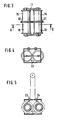
- FIG. 3 shows an embodiment in which the cable drums 15, 16 are each mounted coaxially with other cable drums 18, 19 in the frame 17.
- the ends of a rope are wound on both pairs of rope drums 15, 16 and 18, 19, respectively.
- the cable drums 15, 18 and 16, 19 are rotatably coupled to one another so that they rotate in the same direction. Otherwise, the two groups of cable drums 15, 18 and 16, 19 are coupled to one another via a gear transmission 20, 21, the gears 20 and 21 of which are each arranged between the cable drums 15, 18 and 16, 19.
- Fig. 4 shows that an electric geared motor 22 can be coupled to the gear 20. It is not shown that at least one cable drum, but generally the cable drums 18, 19 have a centrifugal brake.
- the cables wound on the cable drums 15, 16, 18, 19 are led out of the frame 17 or the container 28 via deflection rollers 23, 24, as is shown in FIG. 5.
- the distance between the deflection rollers 23, 24 is such that the cable sections guided over the roller 8 of the boom 7 run essentially parallel to one another.
- the carriage 5 with the boom 7 can be anywhere of the roof 2 of the high-rise building 1.
- the cable drums can be packaged in a protective film, not shown, which is connected to a rip cord, not shown.
- the rip cord is attached on the one hand to the carriage 5 and on the other hand to the protective film.
- Another section of the ripcord can be connected to a safety bolt, not shown, which functions as an unwinding lock for the cable drums and is arranged accordingly.
- the pivot drive 13 of the boom 7 is also actuated by radio remote control.
- the boom swings into the operating position shown in FIG. 2.
- the pull cord is actuated, which on the one hand removes the protective film from the cable drums and on the other hand pulls the safety bolt out of the safety position.
- the unwinding speed can be controlled by adjusting the centrifugal brakes.
- the container 28 sinks to the bottom essentially without vibrations. Length differences occurring in the unwound rope sections are compensated for by the roller 8 of the boom 7. Approx. 5 m above the installation site, the container is decelerated to a fall speed of 0 m / s with a fall damping device, not shown, in order to prevent damage.
- the ropes 14 can be used as rescue ropes.
- other ropes or tools can be used be connected.
- the rescue work can be carried out.
- the electric geared motor 22 is connected to the mains. It automatically winds the ropes 14 back onto their assigned rope drums 15 to 19.
- the safety bolt can be inserted on the roof of the skyscraper, which is now accessible again, and the cable drums can be packed again weatherproof.
- the boom can be mounted on a slewing ring which is mounted on the carriage about a vertical axis.
Landscapes
- Engineering & Computer Science (AREA)
- Mechanical Engineering (AREA)
- Health & Medical Sciences (AREA)
- General Health & Medical Sciences (AREA)
- Business, Economics & Management (AREA)
- Emergency Management (AREA)
- Civil Engineering (AREA)
- Structural Engineering (AREA)
- Emergency Lowering Means (AREA)
Applications Claiming Priority (2)
| Application Number | Priority Date | Filing Date | Title |
|---|---|---|---|
| DE8236927U | 1982-12-31 | ||
| DE19828236927 DE8236927U1 (de) | 1982-12-31 | 1982-12-31 | Einrichtung zur unterstuetzung von rettungsarbeiten, insbesondere in hochhaeusern |
Publications (2)
| Publication Number | Publication Date |
|---|---|
| EP0116102A2 true EP0116102A2 (fr) | 1984-08-22 |
| EP0116102A3 EP0116102A3 (fr) | 1984-12-19 |
Family
ID=6747023
Family Applications (1)
| Application Number | Title | Priority Date | Filing Date |
|---|---|---|---|
| EP83101218A Withdrawn EP0116102A3 (fr) | 1982-12-31 | 1983-02-09 | Appareil pour l'assistance aux travaux de sauvetage spécialement dans des bâtiments dits gratte-ciels |
Country Status (2)
| Country | Link |
|---|---|
| EP (1) | EP0116102A3 (fr) |
| DE (1) | DE8236927U1 (fr) |
Cited By (8)
| Publication number | Priority date | Publication date | Assignee | Title |
|---|---|---|---|---|
| GB2263681A (en) * | 1992-01-28 | 1993-08-04 | Doei Gaiso Yugen Gaisha | Working gondala. |
| WO2014183503A1 (fr) * | 2013-05-13 | 2014-11-20 | Yin Hong | Dispositif de sauvetage à câbles et anneaux de levage pour sortie de secours d'immeubles élevés, et procédé d'utilisation |
| CN105819356A (zh) * | 2016-05-13 | 2016-08-03 | 马宏 | 快运包裹投送装置的应用 |
| CN105923552A (zh) * | 2016-06-07 | 2016-09-07 | 南京信息工程大学 | 简易多层楼房货物运送装置 |
| CN105963866A (zh) * | 2016-05-20 | 2016-09-28 | 魏会芳 | 一种高层建筑消防救援装置 |
| CN105999570A (zh) * | 2016-05-20 | 2016-10-12 | 魏会芳 | 一种高层建筑空中消防救援装置 |
| WO2019111068A1 (fr) * | 2017-12-05 | 2019-06-13 | Harken Italy S.P.A. | Dispositif d'urgence pour secourir des personnes à partir de structures suspendues |
| WO2020201852A1 (fr) * | 2019-04-02 | 2020-10-08 | Harken Italy S.P.A. | Dispositif d'urgence pour secourir des personnes à partir de structures suspendues |
Families Citing this family (1)
| Publication number | Priority date | Publication date | Assignee | Title |
|---|---|---|---|---|
| DE10318301B4 (de) | 2002-04-25 | 2007-02-22 | Sabine Hirsch | Einrichtung zur Rettung von Personen, Gegenstände und dergleichen aus Gebäuden |
Family Cites Families (5)
| Publication number | Priority date | Publication date | Assignee | Title |
|---|---|---|---|---|
| US1882145A (en) * | 1928-06-15 | 1932-10-11 | Seymour S Hirschman | Rotary fire escape |
| US2271426A (en) * | 1939-01-12 | 1942-01-27 | Robert J Harry | Hoist crane construction |
| DE2910573A1 (de) * | 1979-03-17 | 1980-09-18 | Robert Holdermann | Rettungseinrichtung fuer hochbauten |
| CA1121286A (fr) * | 1979-12-04 | 1982-04-06 | Norman A. Johnson | Anticheminant auto-aligneur pour rails |
| US4355699A (en) * | 1980-11-24 | 1982-10-26 | Smith Jr Charles P | Emergency rescue system |
-
1982
- 1982-12-31 DE DE19828236927 patent/DE8236927U1/de not_active Expired
-
1983
- 1983-02-09 EP EP83101218A patent/EP0116102A3/fr not_active Withdrawn
Cited By (9)
| Publication number | Priority date | Publication date | Assignee | Title |
|---|---|---|---|---|
| GB2263681A (en) * | 1992-01-28 | 1993-08-04 | Doei Gaiso Yugen Gaisha | Working gondala. |
| WO2014183503A1 (fr) * | 2013-05-13 | 2014-11-20 | Yin Hong | Dispositif de sauvetage à câbles et anneaux de levage pour sortie de secours d'immeubles élevés, et procédé d'utilisation |
| CN105819356A (zh) * | 2016-05-13 | 2016-08-03 | 马宏 | 快运包裹投送装置的应用 |
| CN105963866A (zh) * | 2016-05-20 | 2016-09-28 | 魏会芳 | 一种高层建筑消防救援装置 |
| CN105999570A (zh) * | 2016-05-20 | 2016-10-12 | 魏会芳 | 一种高层建筑空中消防救援装置 |
| CN105999570B (zh) * | 2016-05-20 | 2019-01-08 | 山东中恒建设集团有限公司 | 一种高层建筑空中消防救援装置 |
| CN105923552A (zh) * | 2016-06-07 | 2016-09-07 | 南京信息工程大学 | 简易多层楼房货物运送装置 |
| WO2019111068A1 (fr) * | 2017-12-05 | 2019-06-13 | Harken Italy S.P.A. | Dispositif d'urgence pour secourir des personnes à partir de structures suspendues |
| WO2020201852A1 (fr) * | 2019-04-02 | 2020-10-08 | Harken Italy S.P.A. | Dispositif d'urgence pour secourir des personnes à partir de structures suspendues |
Also Published As
| Publication number | Publication date |
|---|---|
| EP0116102A3 (fr) | 1984-12-19 |
| DE8236927U1 (de) | 1983-05-05 |
Similar Documents
| Publication | Publication Date | Title |
|---|---|---|
| DE2628041C3 (de) | Fassadenseilaufzug | |
| DE69204729T2 (de) | Hubschrauber getragener Arbeitskorb und dessen Anwendungsmethode für den Austausch eines Teils eines Freileitungskabels. | |
| DE102009053249A1 (de) | Aufzug | |
| DE2400313B2 (de) | Hilfseinrichtung fuer montage- und wartungsarbeiten an einem kuehlturm | |
| DE102017113571A1 (de) | Aufzugsystem | |
| WO2021259969A1 (fr) | Procédé pour construire un système d'ascenseur, et système d'ascenseur apte à mettre en œuvre le procédé | |
| DE2307355A1 (de) | Liftvorrichtung fuer den fuehrerstand eines krans in fachwerkausfuehrung | |
| EP0116102A2 (fr) | Appareil pour l'assistance aux travaux de sauvetage spécialement dans des bâtiments dits gratte-ciels | |
| EP0463709B1 (fr) | Echafaudage suspendu et méthode pour travailler le long d'une façade de bâtiment | |
| DE29619555U1 (de) | Aufzug mit elektrischem und manuellem Antrieb | |
| EP0471305A1 (fr) | Plate-forme attachable à une grue mobile | |
| DE2844857C2 (de) | Fassadenaufzug | |
| DE1531190A1 (de) | Foerdervorrichtung | |
| DE19752232C2 (de) | Seilaufzug mit in den Aufzugschacht hineinragenden Betonsockel | |
| DE8524989U1 (de) | Aus mehreren Führungsschienen gebildeter Schrägaufzug | |
| DE1941940B2 (de) | Fahrzeug mit Hebevorrichtung für großvolumige Kästen, vorzugsweise aus Beton mit Ausnehmungen im Boden für teleskopisch längenveränderliche Beine der Hebevorrichtung | |
| EP0253808B1 (fr) | Poulie | |
| DE202011101434U1 (de) | Kompakt-Greiferlaufkatze | |
| DE102022107239B3 (de) | Pilotseilwinde zur Sicherung von Personen oder Lasten sowie Bauwerk oder Transportmittel, umfassend eine solche | |
| DE3009608C2 (de) | Rettungsschutzsystem an Hochhäusern für die Rettung von Personen im Brandfalle | |
| DE3017462C2 (de) | Einrichtung zum Retten von Personen aus Gebäuden | |
| DE102013109510A1 (de) | Hubvorrichtung | |
| DE878699C (de) | Ruestwagen | |
| DE948390C (de) | Vorrichtung, die dem Verkehr mit dem Schiff dient | |
| DE202022101624U1 (de) | Pilotseilwinde zur Sicherung von Personen oder Lasten sowie Bauwerk oder Transportmittel, umfassend eine solche |
Legal Events
| Date | Code | Title | Description |
|---|---|---|---|
| PUAI | Public reference made under article 153(3) epc to a published international application that has entered the european phase |
Free format text: ORIGINAL CODE: 0009012 |
|
| AK | Designated contracting states |
Designated state(s): AT BE CH DE FR GB IT LI LU NL SE |
|
| PUAL | Search report despatched |
Free format text: ORIGINAL CODE: 0009013 |
|
| AK | Designated contracting states |
Designated state(s): AT BE CH DE FR GB IT LI LU NL SE |
|
| STAA | Information on the status of an ep patent application or granted ep patent |
Free format text: STATUS: THE APPLICATION IS DEEMED TO BE WITHDRAWN |
|
| 18D | Application deemed to be withdrawn |
Effective date: 19850820 |
|
| RIN1 | Information on inventor provided before grant (corrected) |
Inventor name: FELDMANN, BERNHARD, DIPL.-ING. |