EP0116221B1 - Vorrichtung und Verfahren zur Entschwefelung und Erwärmung von geschmolzenen Metallen - Google Patents
Vorrichtung und Verfahren zur Entschwefelung und Erwärmung von geschmolzenen Metallen Download PDFInfo
- Publication number
- EP0116221B1 EP0116221B1 EP83307664A EP83307664A EP0116221B1 EP 0116221 B1 EP0116221 B1 EP 0116221B1 EP 83307664 A EP83307664 A EP 83307664A EP 83307664 A EP83307664 A EP 83307664A EP 0116221 B1 EP0116221 B1 EP 0116221B1
- Authority
- EP
- European Patent Office
- Prior art keywords
- receptacle
- coil
- molten iron
- desulfurizing
- molten metal
- Prior art date
- Legal status (The legal status is an assumption and is not a legal conclusion. Google has not performed a legal analysis and makes no representation as to the accuracy of the status listed.)
- Expired
Links
Images

Classifications
-
- C—CHEMISTRY; METALLURGY
- C21—METALLURGY OF IRON
- C21C—PROCESSING OF PIG-IRON, e.g. REFINING, MANUFACTURE OF WROUGHT-IRON OR STEEL; TREATMENT IN MOLTEN STATE OF FERROUS ALLOYS
- C21C1/00—Refining of pig-iron; Cast iron
- C21C1/02—Dephosphorising or desulfurising
-
- B—PERFORMING OPERATIONS; TRANSPORTING
- B01—PHYSICAL OR CHEMICAL PROCESSES OR APPARATUS IN GENERAL
- B01F—MIXING, e.g. DISSOLVING, EMULSIFYING OR DISPERSING
- B01F33/00—Other mixers; Mixing plants; Combinations of mixers
- B01F33/45—Magnetic mixers; Mixers with magnetically driven stirrers
- B01F33/451—Magnetic mixers; Mixers with magnetically driven stirrers wherein the mixture is directly exposed to an electromagnetic field without use of a stirrer, e.g. for material comprising ferromagnetic particles or for molten metal
-
- C—CHEMISTRY; METALLURGY
- C22—METALLURGY; FERROUS OR NON-FERROUS ALLOYS; TREATMENT OF ALLOYS OR NON-FERROUS METALS
- C22B—PRODUCTION AND REFINING OF METALS; PRETREATMENT OF RAW MATERIALS
- C22B9/00—General processes of refining or remelting of metals; Apparatus for electroslag or arc remelting of metals
- C22B9/003—General processes of refining or remelting of metals; Apparatus for electroslag or arc remelting of metals by induction
-
- C—CHEMISTRY; METALLURGY
- C22—METALLURGY; FERROUS OR NON-FERROUS ALLOYS; TREATMENT OF ALLOYS OR NON-FERROUS METALS
- C22B—PRODUCTION AND REFINING OF METALS; PRETREATMENT OF RAW MATERIALS
- C22B9/00—General processes of refining or remelting of metals; Apparatus for electroslag or arc remelting of metals
- C22B9/10—General processes of refining or remelting of metals; Apparatus for electroslag or arc remelting of metals with refining or fluxing agents; Use of materials therefor, e.g. slagging or scorifying agents
-
- F—MECHANICAL ENGINEERING; LIGHTING; HEATING; WEAPONS; BLASTING
- F27—FURNACES; KILNS; OVENS; RETORTS
- F27B—FURNACES, KILNS, OVENS OR RETORTS IN GENERAL; OPEN SINTERING OR LIKE APPARATUS
- F27B14/00—Crucible or pot furnaces
- F27B14/06—Crucible or pot furnaces heated electrically, e.g. induction crucible furnaces with or without any other source of heat
- F27B14/061—Induction furnaces
-
- H—ELECTRICITY
- H05—ELECTRIC TECHNIQUES NOT OTHERWISE PROVIDED FOR
- H05B—ELECTRIC HEATING; ELECTRIC LIGHT SOURCES NOT OTHERWISE PROVIDED FOR; CIRCUIT ARRANGEMENTS FOR ELECTRIC LIGHT SOURCES, IN GENERAL
- H05B6/00—Heating by electric, magnetic or electromagnetic fields
- H05B6/02—Induction heating
- H05B6/16—Furnaces having endless cores
- H05B6/18—Furnaces having endless cores having melting basin
-
- B—PERFORMING OPERATIONS; TRANSPORTING
- B01—PHYSICAL OR CHEMICAL PROCESSES OR APPARATUS IN GENERAL
- B01F—MIXING, e.g. DISSOLVING, EMULSIFYING OR DISPERSING
- B01F2101/00—Mixing characterised by the nature of the mixed materials or by the application field
- B01F2101/45—Mixing in metallurgical processes of ferrous or non-ferrous materials
-
- F—MECHANICAL ENGINEERING; LIGHTING; HEATING; WEAPONS; BLASTING
- F27—FURNACES; KILNS; OVENS; RETORTS
- F27B—FURNACES, KILNS, OVENS OR RETORTS IN GENERAL; OPEN SINTERING OR LIKE APPARATUS
- F27B14/00—Crucible or pot furnaces
- F27B14/08—Details specially adapted for crucible or pot furnaces
- F27B14/0806—Charging or discharging devices
- F27B2014/0812—Continuously charging
-
- F—MECHANICAL ENGINEERING; LIGHTING; HEATING; WEAPONS; BLASTING
- F27—FURNACES; KILNS; OVENS; RETORTS
- F27B—FURNACES, KILNS, OVENS OR RETORTS IN GENERAL; OPEN SINTERING OR LIKE APPARATUS
- F27B14/00—Crucible or pot furnaces
- F27B14/08—Details specially adapted for crucible or pot furnaces
- F27B2014/0887—Movement of the melt
-
- Y—GENERAL TAGGING OF NEW TECHNOLOGICAL DEVELOPMENTS; GENERAL TAGGING OF CROSS-SECTIONAL TECHNOLOGIES SPANNING OVER SEVERAL SECTIONS OF THE IPC; TECHNICAL SUBJECTS COVERED BY FORMER USPC CROSS-REFERENCE ART COLLECTIONS [XRACs] AND DIGESTS
- Y02—TECHNOLOGIES OR APPLICATIONS FOR MITIGATION OR ADAPTATION AGAINST CLIMATE CHANGE
- Y02P—CLIMATE CHANGE MITIGATION TECHNOLOGIES IN THE PRODUCTION OR PROCESSING OF GOODS
- Y02P10/00—Technologies related to metal processing
- Y02P10/25—Process efficiency
Definitions
- This invention deals with the art of desulfurizing molten metal such as iron for use in casting.
- pig iron In the manufacture of cast iron, pig iron is melted usually in a cupola with coke.
- the molten iron in the cupola contains a considerable amount of sulfur because of the use of coke as a fuel for the cupola.
- Spheroidal graphite cast iron has now been extensively used because of its high quality.
- a spheroid-promoting agent such as silicon is added to the molten iron in the cupola to form the spheroidal graphite cast iron.
- the sulfur content of the molten iron prevents the graphite in the resultant cast iron from becoming spheroidal to a desired degree. Therefore, it is a common practice in the art to desulfurize the molten iron before the spheroid-promoting agent is applied to the molten iron.
- the desulfurization is carried out by applying a pulverized desulfurizing agent to the molten iron and then agitating this molten iron. This agitation is necessary for promoting the reaction of the desulfurizing agent with the sulfur in the molten iron.
- Calcium carbide, calcium oxide or the like is used as the desulfurizing agent. In the case where calcium carbide is used as the desfulfurizing agent, the following reaction is obtained at the time of the desulfurization:
- CaS constitutes a slag and floats on the top of the molten iron.
- This slag is gasified and dissipated into the ambient atmosphere when the molten iron is at elevated temperatures. Since the desulfurizing agent has a relatively low specific gravity, it is necessary to agitate the molten metal to promote the above-mentioned reaction.
- One such desulfurizing method is known as a porous plug method. In this method, a porous plug is mounted on the bottom of a vessel for holding the molten iron. The desulfurizing agent is applied to the molten iron in the vessel, and inert gas such as nitrogen gas is introduced into the vessel through the porous plug to produce bubbles which move upwardly to agitate the molten iron.
- Another conventional desulfurizing method is known as a gas injection method.
- a pipe made of a refractory material is introduced into the molten iron in a vessel.
- Powder of carbide carried by nitrogen gas is fed through the refractory pipe to the molten iron in the vessel, thereby causing the agitation of the molten iron to effect the desulfurization thereof.
- These two desulfurizing methods have been found disadvantageous in that the molten iron in the vessel is subjected to a relatively large temperature drop because of the agitation of the molten iron. Therefore, it has heretofore been necessary to provide separate heating means for heating the desulfurized molten iron to compensate for the temperature drop thereof. This is undesirable from an economical point of view.
- the temperature of the molten iron discharged from the cupola in 1550°C, and the temperature of the molten iron in the desulfurizing apparatus of the porous plug type is 1450°C.
- the temperature of the desulfurized molten iron discharged from the desulfurizing apparatus is 1400°C.
- the desulfurized molten iron is transferred to molds to form castings.
- the temperature of the molten iron required for casting products of relatively small size or thickness is 1400 to 1430°C.
- the molten iron discharged from the desulfurizing apparatus is further subjected to a temperature drop during a time period when it is transferred to the molds.
- the temperature of the molten iron discharged from the desulfurizing apparatus is not practical.
- the above-mentioned heating means such as an induction furnace is required, which increases the installation cost.
- U.K. Patent 523435 It is known from U.K. Patent 523435 to provide a desulphurizing and heating receptacle having an open top, closed bottom and a side wall surrounded by an induction coil.
- the outlet passage is located at the bottom of the receptacle and is not located within the coil surround the side wall.
- JP-A-57181313 It is known from JP-A-57181313 to provide a desulphurising receptacle having an open top, closed bottom and a side wall adjacent to one side of which there is located an inductor for causing circulation of the molten metal within the receptacle.
- apparatus for desulfurizing and heating molten metal which comprises a receptacle having an open top, a closed bottom and a side wall surrounded by an induction coil which is arranged to agitate molten metal located in the receptacle by inducing eddy currents therein, a first feed means for supplying molten metal to said receptacle and a second feed means for supplying a desulfurizing agent to said receptacle characterised in that said receptacle is generally circular in cross-section and is defined by a body of a refractory material which also defines a passageway extending upwardly from an outlet port formed adjacent to the bottom of the receptacle to an outlet for discharging molten metal from the apparatus, an induction coil surrounding the body so that both said receptacle and said passgeway are disposed within said coil, the upper end of said coil being disposed at a level generally equal to the level of said outlet so that the level of the
- the flow rate of the molten metal discharged from the first feed means and the capacity of the receptacle are determined in such a manner that a time of residence of the molten metal in the receptacle is 5 to 10 minutes.
- the ratio of the inner diameter to depth of the receptacle is determined in such a manner that a height of a bulged surface of the molten metal caused by the agitation thereof is 8 to 16 cm when electric power is supplied to the coil to raise the temperature of the molten metal in the receptacle by 50 to 100°C.
- FIGs. 1 and 2 show an electromagnetic desulfurizing apparatus 10 which comprises a one-piece body 11 of a refractory material having a circular receptacle or crucible 12 and an extension 13 extending from the outer peripheral wall of the receptacle 12, the receptacle 12 having an open top.
- An opening 15 is formed through the extension 13 adjacent to the receptacle 12, the opening 15 also having an open top.
- An electric coil 16 is wound around the receptacle 12, the coil 16 passing through the opening 15.
- a pair of upper and lower annular support members 18 and 19 are fixedly secured to the body 11 by bolts or the like and hold the coil 16 therebetween against movement, the annular members 18 and 19 passing through the opening 15.
- a passageway 20 extends from the bottom 12a of the receptacle 12 through the extension 13 to an outlet 21 provided at the upper portion 13a of the extension 13, the outlet 21 being disposed horizontally.
- the receptacle 12 communicates with the passageway 20.
- a plurality of elongated iron members 23 are provided around the coil 16 in circumferentially spaced relation to one another, the iron members 23 being disposed vertically and supported by the upper and lower annular members 18 and 19.
- an iron shell is mounted in surrounding relation to the apparatus body 11.
- the iron members 23 serve as paths for magnetic fluxes produced by the excited coil 16 and prevent any leakage magnetic flux from flowing to the iron shell, so that the generation of heat in the iron shell due to eddy current is prevented.
- the coil 16 comprises a hollow wire of copper, and water is adapted to pass through the interior of the hollow wire so as to cool the coil 16 during the excitation thereof.
- Molten iron F is fed from a cupola (not shown) to the receptacle 12 through a feed trough 25.
- a desulfurizing agent 30 is fed to the receptacle 12 through a feed pipe 26.
- the desulfurizing agent is in the form of powder and is composed predominantly of either calcium carbide (CaC 2 ) or calcium oxide (CaO).
- the body 11. of the electromagnetic desulfurizing apparatus 10 is formed by compacting a refractory powder material into a predetermined shape and sintering it.
- the coil 16 serves to increase the temperature of the molten iron F in the receptacle 12 and also to agitate the molten iron F.
- the molten iron is continuously fed from the cupola through the feed trough 25 to the receptacle 12 at a predetermined feed rate.
- the desulfurizing agent is continuously fed to the receptacle 12 through the feed pipe 26 at a predetermined feed rate.
- the desulfurizing agent is uniformly mixed with the molten iron F in the receptacle 12 through the agitation of the molten iron effected by the excited coil 16 as mentioned above, so that the molten iron F is desulfurized.
- the desulfurized molten iron F is continuously discharged from the outlet 21 through the passageway 20 and is transferred to molds (not shown) for the casting of products.
- the desulfurizing molten iron is continuously discharged from the outlet 21 at a rate equal to the rate of feed of the molten iron to the receptacle 12.
- the outlet 21 is disposed at such a level that the level of the molten iron F in the receptacle 12 becomes generally equal to the upper end of the coil 16 when the desulfurized molten iron begins to be discharged from the outlet 21.
- the upper end of the coil 16 is generally equal to the level of the outlet 21. The reason that the upper end of the coil 16 is disposed at the level of the molten iron F in the receptacle 12 is to enhance the utilization of the electromagnetic induction to which the molten iron is subjected, so that a satisfactory agitation of the molten iron can be achieved.
- the upper end of the coil 16 is disposed at a level lower than the level of the molten iron F in the receptacle 12, the upper portion of the molten iron near its surface is not subjected to electromagnetic induction so that this upper portion is not satisfactorily agitated because of the presence of the static pressure, although the utilization of the electromagnetic induction is improved.
- the upper end of the coil 16 is disposed at a level higher than the level of the molten iron F in the receptacle 12, the utilization of the electromagnetic induction is worsened.
- the temperature of the molten iron at each stage of the process is as follows:
- the temperature of the molten iron discharged from the cupola is 1550°C; the temperature of the molten iron in the desulfurizing apparatus 10is1500°C; and the temperature of the desulfurized molten iron discharged from the desulfurizing apparatus 10 is 1450°C.
- the desulfurized molten iron is applied to molds for casting.
- the temperature of the molten iron in the desulfurizing apparatus 10 is 50°C higher than the temperature of the molten iron in the conventional desulfurizing apparatus of the porous plug type.
- the cupola outputs 2000 kg of molten iron per hour, and the temperature of the molten iron discharged from the cupola is 1550°C.
- the desulfurizing apparatus 10 has a capacity for holding 400 kg of the molten iron.
- the coil 16 has an electric power of 100 KW.
- a residence time of the molten iron in the desulfurizing apparatus 10 is 12 minutes (400/2000x60).
- the molten iron which has been introduced into the passageway 20 before the molten iron in the receptacle 12 reaches the predetermined level generally equal to the level of the outlet 21, is not subjected to desulfurization and therefore may be discarded.
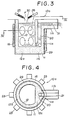
- Figs. 3 and 4 show a desulfurizing apparatus 10a according to the present invention which differs from the desulfurizing apparatus 10 of Figs. 1 and 2 in that a passageway 20 is disposed vertically adjacent to a receptacle 12 and communicates with a horizontally-disposed outlet 21 and the receptacle 12 at its upper and lower ends, respectively, and that.the passageway 21 is disposed within an electrical coil 16wound around a body 11 of the desulfurizing apparatus 10a.
- a horizontal protrusion 11 b extends from the upper portion of the body 11 adjacent to the protuberance 11 a.
- the open-top receptacle 12 has a semi-circular cross-section and is defined by a semi-circular wall 12b, a thickened wall 12c and a bottom or base 12a.
- the passageway 20 is formed through the thickened wall 12c disposed in registry with the protuberance 11a, and communicates with the receptacle 12 through a port 12d formed in the thickened wall 12c adjacent to the bottom 12a.
- the outlet 21 for discharging the desulfurized .
- molten iron is formed through the protrusion 11 b.
- a refractory member 29 is mounted on the outer periphery of the body 11.
- the coil 16 is mounted around the refractory member 29.
- Iron members 23 are mounted around the coil 16 in circumferentially spaced relation to one another.
- molten iron F is fed from a cupola (not shown) to the receptacle 12 through a feed trough 25.
- a desulfurizing agent 30 in the form of powder is fed to the receptacle 12 through a feed tube 26.
- That portion of the coil 16 disposed in registry with the protuberance 11 a is displaced downwardly with respect to the remaining major portion of the coil 16. Said that portion of the coil 16 is held against the underside of the protrusion 11 b. And, the upper end of the coil 16 is disposed generally at the level of the molten iron F in the receptacle 12 which is equal to the level of the outlet 21. With this arrangement, the molten iron F in the receptacle 12 is efficiently agitated for the reasons described above for the desulfurizing apparatus 10 of Figs. 1 and 2.
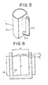
- a core 31 of iron shown in Fig. 5 is used for forming the desulfurizing apparatus 10a.
- the core 31 of a one-piece construction comprises a hollow body 31a, a tubular portion 31b, and a connecting portion 31c interconnecting the body 31 a and the tubular body 31b, the hollow body 31a having an open top and a closed bottom.
- the hollow body 31a, the connecting portion 31c and the tubular body 31 b correspond in shape to the receptacle 12, the port 12d and the passageway 20, respectively.
- the refractory member 29 is first placed on a flat surface, and a predetermined amount of powder refractory material is introduced into the refractory member 29 to provide the base 11 c.
- the core 31 is placed in the refractory member 29 with its bottom resting on the base 11c, the core 31 being disposed in radially spaced relation to the refractory member 29 to form a space therebetween.
- powder refractory material is filled in this space, using a filling vibrator.
- the coil 16 is mounted around the refractory member 29.
- the coil 16 is excited so that the core 31 is subjected to electromagnetic induction and is heated to elevated temperatures.
- the powder refractory material is sintered.
- the molten iron F is introduced into the core 31, the core 31 is melted by the heat of the molten iron to form the receptacle 12, the port 12d and the passageway 20.
- the sintering of the refractory material is further effected.
- the desulfurizing apparatus 10a can be manufactured easily and quickly. Therefore, when the refractory material of the desulfurizing apparatus is subjected to damage due to the slag, the body 11 is destroyed, and a new desulfurizing apparatus can be easily manufactured in the manner described.
- the iron members 23 can be provided at any suitable locations around the coil 16. With this construction, external structural members are prevented from being subjected to heat due to eddy current caused by the coil 16.
- the passageway 20 is disposed within the coil 16 and positioned adjacent to the receptacle 12, the heat of the molten iron F in the receptacle is transmitted to the desulfurized molten iron in the passageway 20, so that the molten iron in the passageway 20 is subjected to less temperature drop.
- the residence time T (min.) of the molten iron F in the receptacle 12 is determined by the following formula: wherein W (kg) is a capacity of the receptacle 12, i.e., the amount of the molten iron which the receptacle 12 can hold, and Q (kg/min.) is a flow rate of the molten iron discharged from the feed trough 25 leading to the cupola.
- the residence time T is the time used for desulfurizing the molten iron F. With this desulfurizing apparatus, it has been found that the optimum residence time T is 5 to 10 minutes.
- the flow rate Q of the molten iron from the feed trough 25 is predetermined. Therefore, the capacity W of the receptacle 12 is so determined that the residence time T is 5 to 10 minutes.
- the temperature of the molten iron discharged from the cupola is 1530°C.
- the temperature of the molten iron in the desulfurizing apparatus is 1450°C (optimum temperature: 1500°C).
- the temperature of the molten iron subjected to the graphite spheroidal treatment is 1400°C (optimum temperature: 1480°C).
- the casting temperature is 1350°C (optimum temperature: 1420°C).
- electric power P determined by the above formula (4) must be induced in the molten iron in the receptacle 12, and electric power supplied to the coil 16 is determined based on the electric power P. Almost all of the electric power induced in the molten iron in the receptacle 12 is converted to heat energy, and not more than 0.1% of the induced electric power serves as energy for agitating the molten iron.
- Fig. 6 shows a model receptacle 33 of a cylindrical shape corresponding to the receptacle 12 of the desulfurizing apparatus 10a.
- the model receptacle 33 has an inner diameter d and an effective depth I.
- the depth I is determined by the level of the outlet 21.
- the height h of the bulged portion is represented by the following formula: wherein p(Qcm) is specific resistance of the molten iron, P (kw) is electric power induced in the molten iron, s (g/cm 3 ) is specific gravity of the molten iron, and f (Hz) is frequency of electric current supplied to the coil 16.
- the height h corresponds to the intensity of the agitation of the molten iron. It has been found that when the heigh h is 8 to 16 cm, the molten iron is sufficiently agitated to effect a satisfactory desulfurization of the molten iron. As can be seen from the above formula (5), the agitation force is proportional to the electric power supplied to the coil 16 and is inversely proportional to the diameter and depth of the receptacle.
- h is replaced by 8 to 16
- P is replaced by a value determined by a desired temperature rise of the molten iron in the receptacle, so that a valve of ⁇ (dI) which can achieve a sufficient agitation is determined.
- An effective capacity V of the model receptacle 33 (Fig. 6) is obtained from the following:
- the capacity W of the receptacle is obtained from the following:
- the inner diameter d and depth I of the receptacle which are minimum but can achieve the maximum efficiency of the desulfurization, agitation and temperature rise, are obtained in the following manner:
Landscapes
- Chemical & Material Sciences (AREA)
- Engineering & Computer Science (AREA)
- Mechanical Engineering (AREA)
- Metallurgy (AREA)
- Organic Chemistry (AREA)
- Materials Engineering (AREA)
- Manufacturing & Machinery (AREA)
- Chemical Kinetics & Catalysis (AREA)
- General Engineering & Computer Science (AREA)
- Physics & Mathematics (AREA)
- Electromagnetism (AREA)
- Refinement Of Pig-Iron, Manufacture Of Cast Iron, And Steel Manufacture Other Than In Revolving Furnaces (AREA)
- Treatment Of Steel In Its Molten State (AREA)
Claims (6)
Applications Claiming Priority (4)
| Application Number | Priority Date | Filing Date | Title |
|---|---|---|---|
| JP224666/82 | 1982-12-21 | ||
| JP57224666A JPS59116310A (ja) | 1982-12-21 | 1982-12-21 | 電磁誘導撹拌装置 |
| JP224667/82 | 1982-12-21 | ||
| JP57224667A JPS59116311A (ja) | 1982-12-21 | 1982-12-21 | 電磁脱硫装置 |
Publications (2)
| Publication Number | Publication Date |
|---|---|
| EP0116221A1 EP0116221A1 (de) | 1984-08-22 |
| EP0116221B1 true EP0116221B1 (de) | 1989-03-01 |
Family
ID=26526186
Family Applications (1)
| Application Number | Title | Priority Date | Filing Date |
|---|---|---|---|
| EP83307664A Expired EP0116221B1 (de) | 1982-12-21 | 1983-12-16 | Vorrichtung und Verfahren zur Entschwefelung und Erwärmung von geschmolzenen Metallen |
Country Status (3)
| Country | Link |
|---|---|
| US (1) | US4512801A (de) |
| EP (1) | EP0116221B1 (de) |
| DE (1) | DE3379275D1 (de) |
Families Citing this family (6)
| Publication number | Priority date | Publication date | Assignee | Title |
|---|---|---|---|---|
| DE4114683A1 (de) * | 1991-05-06 | 1992-11-12 | Leybold Ag | Induktionsofen fuer schmelz- und giesszwecke mit einem geschlossenen ofenkessel |
| IT1288437B1 (it) * | 1996-11-15 | 1998-09-22 | S E Tri Srl | Procedimento ed impianto per la fusione e purificazione di leghe di alluminio, rame, ottone, piombo e bronzo |
| AUPR203200A0 (en) * | 2000-12-12 | 2001-01-11 | Technological Resources Pty Limited | Desulphurizing molten iron |
| BRPI0806778B1 (pt) * | 2007-01-16 | 2019-03-26 | Prime Polymer Co., Ltd | Composição de resina de etileno moldada a sopro, artigo moldado a sopro e tanque de combustível |
| CN103060506B (zh) * | 2013-01-18 | 2015-11-04 | 莱芜钢铁集团有限公司 | 一种电磁感应脱硫铁水罐 |
| DE102021125159A1 (de) | 2021-09-28 | 2023-03-30 | Ald Vacuum Technologies Gmbh | Vorrichtung und ein Verfahren zum Herstellen eines Feingussbauteils |
Family Cites Families (8)
| Publication number | Priority date | Publication date | Assignee | Title |
|---|---|---|---|---|
| US2243514A (en) * | 1938-01-24 | 1941-05-27 | Tigerschiold Kjell Magnus | Desulphurization of cast iron |
| GB523435A (en) * | 1938-03-30 | 1940-07-15 | Kjell Magnus Tigerschiold | Improvements relating to metallurgical reactions effected by electrical induction |
| US2319402A (en) * | 1941-01-18 | 1943-05-18 | Rasex Res Corp | Desulphurizing apparatus |
| FR1095280A (fr) * | 1953-03-18 | 1955-05-31 | Arbed | Procédé et installation de désulfuration de la fonte |
| GB861383A (en) * | 1958-08-12 | 1961-02-22 | Siderurgie Fse Inst Rech | Method for desulphurising molten metal and in particular liquid pig iron |
| AU422827B2 (en) * | 1967-10-03 | 1972-03-28 | Monzino Riotinto Of Australia Limited | Continuous degassing of metals |
| US3490897A (en) * | 1967-10-27 | 1970-01-20 | Olin Mathieson | Process for producing low oxygen,high conductivity copper |
| BE755733A (fr) * | 1969-09-06 | 1971-02-15 | Rheinstahl Huettenwerke Ag | Procede et dispositif de desulfuration de fonte brute |
-
1983
- 1983-12-15 US US06/561,650 patent/US4512801A/en not_active Expired - Lifetime
- 1983-12-16 DE DE8383307664T patent/DE3379275D1/de not_active Expired
- 1983-12-16 EP EP83307664A patent/EP0116221B1/de not_active Expired
Non-Patent Citations (1)
| Title |
|---|
| "Die physikalishe Chemie der Eisen und Stahlerzeugung", 1964, p. 195-206 * |
Also Published As
| Publication number | Publication date |
|---|---|
| DE3379275D1 (en) | 1989-04-06 |
| EP0116221A1 (de) | 1984-08-22 |
| US4512801A (en) | 1985-04-23 |
Similar Documents
| Publication | Publication Date | Title |
|---|---|---|
| US3724829A (en) | Apparatus for the introduction of volatile additives into a melt | |
| EP0240998A1 (de) | Verfahren und Vorrichtung zum Schmelzen von Metall | |
| US4512801A (en) | Apparatus for and method of desulfurizing and heating molten metal | |
| US3918692A (en) | Apparatus for refining molten metals and molten metal refining process | |
| US3820767A (en) | Apparatus for the treatment of molten metal | |
| US4032704A (en) | Method and apparatus for treating a metal melt | |
| US2319402A (en) | Desulphurizing apparatus | |
| US2528209A (en) | Apparatus for smelting metals | |
| CN1039651A (zh) | 分离钢和炉渣的装置 | |
| US1937064A (en) | Method of treating metals | |
| US3579324A (en) | Method for induction melting of fine particles | |
| US1851984A (en) | Electric furnace | |
| KR20010040915A (ko) | 미세 금속 입자 및/또는 금속 함유 입자를 용융시키기위한 방법 및 유도 전기로 | |
| US3414250A (en) | Ladle for use in treatment of molten metal | |
| US5134628A (en) | Direct-current arc furnace having bottom electrodes with bath agitation electromagnet | |
| US3700779A (en) | Method of treatment of liquid steel under vacuum | |
| US5738823A (en) | Meltdown apparatus | |
| US4363653A (en) | Method and apparatus for melting solid pieces of metal | |
| US1939623A (en) | Electric induction furnace and method of operating it | |
| US5160477A (en) | Temperature maintenance and metallurgical treatment furnace | |
| US3483301A (en) | Horizontal coreless induction furnace | |
| US3934863A (en) | Apparatus for refining molten metal and molten metal refining process | |
| US3819842A (en) | Method and furnace for maintaining the temperature level of metal melts | |
| KR100328035B1 (ko) | 진공순환탈가스설비의용강승온방법및그장치 | |
| RU2061057C1 (ru) | Устройство для обработки металлов газами с электроподогревом |
Legal Events
| Date | Code | Title | Description |
|---|---|---|---|
| PUAI | Public reference made under article 153(3) epc to a published international application that has entered the european phase |
Free format text: ORIGINAL CODE: 0009012 |
|
| AK | Designated contracting states |
Designated state(s): DE FR GB |
|
| 17P | Request for examination filed |
Effective date: 19850117 |
|
| GRAA | (expected) grant |
Free format text: ORIGINAL CODE: 0009210 |
|
| AK | Designated contracting states |
Kind code of ref document: B1 Designated state(s): DE FR GB |
|
| REF | Corresponds to: |
Ref document number: 3379275 Country of ref document: DE Date of ref document: 19890406 |
|
| ET | Fr: translation filed | ||
| PLBE | No opposition filed within time limit |
Free format text: ORIGINAL CODE: 0009261 |
|
| STAA | Information on the status of an ep patent application or granted ep patent |
Free format text: STATUS: NO OPPOSITION FILED WITHIN TIME LIMIT |
|
| 26N | No opposition filed | ||
| PGFP | Annual fee paid to national office [announced via postgrant information from national office to epo] |
Ref country code: GB Payment date: 19911209 Year of fee payment: 9 Ref country code: FR Payment date: 19911209 Year of fee payment: 9 |
|
| PGFP | Annual fee paid to national office [announced via postgrant information from national office to epo] |
Ref country code: DE Payment date: 19920131 Year of fee payment: 9 |
|
| PG25 | Lapsed in a contracting state [announced via postgrant information from national office to epo] |
Ref country code: GB Effective date: 19921216 |
|
| GBPC | Gb: european patent ceased through non-payment of renewal fee |
Effective date: 19921216 |
|
| PG25 | Lapsed in a contracting state [announced via postgrant information from national office to epo] |
Ref country code: FR Effective date: 19930831 |
|
| PG25 | Lapsed in a contracting state [announced via postgrant information from national office to epo] |
Ref country code: DE Effective date: 19930901 |
|
| REG | Reference to a national code |
Ref country code: FR Ref legal event code: ST |