EP0116231A2 - Baignoire - Google Patents
Baignoire Download PDFInfo
- Publication number
- EP0116231A2 EP0116231A2 EP83307951A EP83307951A EP0116231A2 EP 0116231 A2 EP0116231 A2 EP 0116231A2 EP 83307951 A EP83307951 A EP 83307951A EP 83307951 A EP83307951 A EP 83307951A EP 0116231 A2 EP0116231 A2 EP 0116231A2
- Authority
- EP
- European Patent Office
- Prior art keywords
- container
- water
- jets
- base
- seating
- Prior art date
- Legal status (The legal status is an assumption and is not a legal conclusion. Google has not performed a legal analysis and makes no representation as to the accuracy of the status listed.)
- Withdrawn
Links
Images


Classifications
-
- A—HUMAN NECESSITIES
- A47—FURNITURE; DOMESTIC ARTICLES OR APPLIANCES; COFFEE MILLS; SPICE MILLS; SUCTION CLEANERS IN GENERAL
- A47K—SANITARY EQUIPMENT; ACCESSORIES THEREFOR, e.g. TOILET ACCESSORIES
- A47K3/00—Baths; Showers; Appurtenances therefor
- A47K3/02—Baths
- A47K3/06—Collapsible baths, e.g. inflatable; Movable baths
-
- A—HUMAN NECESSITIES
- A61—MEDICAL OR VETERINARY SCIENCE; HYGIENE
- A61H—PHYSICAL THERAPY APPARATUS, e.g. DEVICES FOR LOCATING OR STIMULATING REFLEX POINTS IN THE BODY; ARTIFICIAL RESPIRATION; MASSAGE; BATHING DEVICES FOR SPECIAL THERAPEUTIC OR HYGIENIC PURPOSES OR SPECIFIC PARTS OF THE BODY
- A61H33/00—Bathing devices for special therapeutic or hygienic purposes
- A61H33/0087—Therapeutic baths with agitated or circulated water
-
- A—HUMAN NECESSITIES
- A61—MEDICAL OR VETERINARY SCIENCE; HYGIENE
- A61H—PHYSICAL THERAPY APPARATUS, e.g. DEVICES FOR LOCATING OR STIMULATING REFLEX POINTS IN THE BODY; ARTIFICIAL RESPIRATION; MASSAGE; BATHING DEVICES FOR SPECIAL THERAPEUTIC OR HYGIENIC PURPOSES OR SPECIFIC PARTS OF THE BODY
- A61H33/00—Bathing devices for special therapeutic or hygienic purposes
- A61H33/02—Bathing devices for use with gas-containing liquid, or liquid in which gas is led or generated, e.g. carbon dioxide baths
- A61H33/027—Gas-water mixing nozzles therefor
-
- A—HUMAN NECESSITIES
- A61—MEDICAL OR VETERINARY SCIENCE; HYGIENE
- A61H—PHYSICAL THERAPY APPARATUS, e.g. DEVICES FOR LOCATING OR STIMULATING REFLEX POINTS IN THE BODY; ARTIFICIAL RESPIRATION; MASSAGE; BATHING DEVICES FOR SPECIAL THERAPEUTIC OR HYGIENIC PURPOSES OR SPECIFIC PARTS OF THE BODY
- A61H33/00—Bathing devices for special therapeutic or hygienic purposes
- A61H33/60—Components specifically designed for the therapeutic baths of groups A61H33/00
- A61H33/6068—Outlet from the bath
-
- A—HUMAN NECESSITIES
- A61—MEDICAL OR VETERINARY SCIENCE; HYGIENE
- A61H—PHYSICAL THERAPY APPARATUS, e.g. DEVICES FOR LOCATING OR STIMULATING REFLEX POINTS IN THE BODY; ARTIFICIAL RESPIRATION; MASSAGE; BATHING DEVICES FOR SPECIAL THERAPEUTIC OR HYGIENIC PURPOSES OR SPECIFIC PARTS OF THE BODY
- A61H33/00—Bathing devices for special therapeutic or hygienic purposes
- A61H2033/0008—Arrangement for cleaning the installation before or after use
- A61H2033/0033—Arrangement for cleaning the installation before or after use by draining-off pumps, nozzles, waterlines by gravity
-
- A—HUMAN NECESSITIES
- A61—MEDICAL OR VETERINARY SCIENCE; HYGIENE
- A61H—PHYSICAL THERAPY APPARATUS, e.g. DEVICES FOR LOCATING OR STIMULATING REFLEX POINTS IN THE BODY; ARTIFICIAL RESPIRATION; MASSAGE; BATHING DEVICES FOR SPECIAL THERAPEUTIC OR HYGIENIC PURPOSES OR SPECIFIC PARTS OF THE BODY
- A61H33/00—Bathing devices for special therapeutic or hygienic purposes
- A61H33/60—Components specifically designed for the therapeutic baths of groups A61H33/00
- A61H33/601—Inlet to the bath
- A61H33/6021—Nozzles
Definitions
- This invention relates to bathing apparatus and in particular, but not exclusively, to baths and associated equipment whereby water jets are introduced into a body of water.
- bathing apparatus including a container for a body of water and into which container water jets with entrained air are directed.
- Such apparatus is sometimes called a spa bath and is intended to provide a stimulating effect on persons immersed in the body of water.
- Conventionally such apparatus includes a container of relatively large size so that several persons can avail themselves of the apparatus simultaneously but such a large container is unsuitable for the usual domestic situation when the apparatus is to be installed in a bathroom, it requires a large amount of water and is potentially unhygienic.
- An object of the invention is to provide bathing apparatus capable of use as a spa bath which is readily installed in the typical bathroom facility.
- bathing apparatus comprises an upright two-part container having an interior space of generally circular, triangular or other curvilinear shape in horizontal cross-section for containing a body of water, seating means in the container located in a lower portion of the container and spaced from the base of the container, and feed means for feeding water into the container, and the two parts of the container being interconnectable to define a unit sealed at the connection between the parts.
- the interior of the container is circular in horizontal cross-section and the maximum diameter of the container is approximately equal to the distance between the base of the interior space and the upper edge of said interior space and the two parts of the container comprise an upper part and a lower part, the lower part defining the seating means.
- the apparatus includes a plurality of water jets located in the upright wall of the container and arranged to direct jets of water inwardly of the container into the body of water.
- the water jets may be arranged so that air is entrained in the water before the water issues from the jets, in known manner, and the water jets are arranged at such a level that the jets issue below the normal water surface level of the body of water.
- the container is formed of a plastics moulding and the container is made in two parts, in order that it can be easily installed and can pass through restricted openings, such as doorways, the parts being arranged to be assembled together in situ.
- the lower part has a circular flanged edge at its upper end and the upper part has a cooperating flanged edge at its lower end.
- the water jets are conveniently located towards the upper end of said lower part and above the level of a seating surface of the seating means, the jets being arranged to discharge water received from the container into the body of water.
- the interior of the container is preferably cylindrical and the seat means is formed by recessing a portion of the container inwardly from the cylindrical envelope of the container to provide a horizontal seat surface.
- a further water jet is located in said seat surface and is directed upwardly.
- the pump means is conveniently located under the seat surface externally of the container and above the base of the container. In this way when the container is emptied of water any water remaining in the pump means can drain back into the container.
- An outlet drainage opening is located in the base of the container to drain off water after use.
- the container will have an internal height of the order of 900 mm with an internal diameter of approximately the same dimension. With these dimensions the seat means is readily able to accommodate a bather and to provide adequate depth of water without excessive amounts of water being necessary.
- the container will be filled with water up to the desired level by tap means positioned over the container.
- the pump means will be activated and this will draw water from the container for circulation to the various water jets and discharge back into the container.
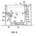
- the bathing apparatus shown is intended for installation in the corner of a bathroom, as shown, and the apparatus includes a generally cylindrical container 10.
- the container 10 is conveniently a plastics moulding formed in two parts, an upper part 11 and a lower part 12.
- the upper part 11 has at its upper end an outwardly-directed lip 13 and at its lower end an outwardly-directed flange 14. Towards its upper end the part 11 has an overflow opening 15.
- the lower part 12 has an outwardly-directed flange 17 at its upper end for assembly of the parts together, as will be described, and below the level of the flange 17 are formed openings for receiving water jet nozzles 18.
- the lower part 12 of the container is recessed inwardly to define the seat 20 which includes a horizontal seat surface 21 lying below the level of the nozzles 18 and opposite the corner of the room in which the apparatus is positioned.
- a further nozzle 22 is provided in the seat surface 21 directed upwardly to act in the manner of a bidet nozzle.
- a water discharge 24 closable by a plug 25 whereby the container is drained after use.
- Piping 26 leads from the overflow opening l5 to the discharge 24 to drain off any excess water in the container.
- a water pump 28 is located under the seat 20 in the space afforded by the recessed portion 29 of the container, the pump 28 lying above the level of the base 30 of the container.
- the pump 28 draws water from the lower region of the container, after the container has been filled, through a pipe 31 opening into a side wall of the container and towards the base 30.
- the pipe 31 also acts as a drainage pipe for draining off water in the pump and associated pipework after the container is emptied of water.
- the pump 28 distributes water from the container through a circumferential pipe 32 to the nozzles 18 and to the nozzle 22 after the container has been filled with water to the desired level which is a level above the nozzles 18 and below the uppermost edge of the container.
- Filling of the container is by means of conventional water taps 33 operated to give the desired water temperature.
- the nozzles 18 are of a form such that air is entrained in the water before the water enters the container and the nozzles are adjustable in the directions in which the water issues from the nozzles but the nozzles 18 may, like the nozzle 22,discharge only water.
- the container 10 is supported on a support 35 on the floor and a semi-cylindrical panel 36 fits between the floor and the lips 13 around the exposed side of the container to give a pleasing finish to the apparatus when installed.
- the external surface of the container may have fitted to it a layer of insulating material to reduce heat loss from the water in the container.
- the internal dimensions of the container are such that the diameter of the container is approximately equal to the depth and a dimension of about 900 mm is deemed suitable for this purpose. This gives a compact arrangement having adequate depth to obtain the full benefit of the water jets without occupying undue space.
- the apparatus can be used as a shower base or tray by having a shower head positioned over the container.
- the flanges l4 and 17 are provided with a cooperating groove on a mating surface of one part and a lug on the mating surface of the other part.
- a bolted connection (not shown) through the flanges 14 and 17 is employed, or a circumferential ring (not shown) engages the flanges 14 and 17 around the container and is connected and tightened by a bolt.
- a sealing ring (not shown) may be located between the flanges.
- a control switch 38 for operating the motor 28 is mounted on the container surround together with a control 39 for adjusting the amount of air issuing from the jets with the water. Also shown in Fig. 4 is a conduit 40 extending around the exterior of the container by which air is directed to the jets 18. It will be seen that in Fig. 4 the seat 20 is located adjacent the corner of the room.
- Fig. 5 shows a jet assembly for providing water jets in which air is entrained and by which it is ensured that water does not remain in the assembly after use, thereby avoiding discharge of stagnant water at the commencement of use of the apparatus.
- the assembly includes a water conduit 42 having an outlet 45 by which water from the conduit is directed into a nozzle chamber 43 towards an adjustable nozzle member 44.
- the water passes from the outlet 45 through the chamber 43 and through an opening 46 in the member 44 which is aligned with the outlet 45.
- Air is admitted to the chamber 43 from the air conduit 47 situated above the chamber and as water passes through the opening 46 air is entrained with the water and is discharged with the water into the body of water in the container.
- the assembly is fixed to the wall of the container 10 by a flanged securing member 48 fitting through a hole in said wall and in screw-threaded engagement with the body of the chamber 43.
- the base of the chamber is formed with an outlet opening 50 which communicates through a pipe 51 with the water discharge of the apparatus.
- the container may be of circular cross-section but tapering outwardly in the upwards direction.
- the container may, in cross-section, be of other curvilinear shape, such as an elliptical shape or a generally triangular shape with rounded corners. In each case, however, it is important that the container is of a depth to accommodate a seat with sufficient depth above the seat that the user can be immersed above waist level.
- a separate control is usefully provided for the seat jet nozzle 22 to be inoperative while the other jets 18 remain in operation.
- jet nozzles 18 and/or 22 may be omitted in which case the apparatus may function as a conventional bath.
- the bath is particularly suited to the infirm unable to sit in a conventional bath and, to assist in making an entry into the bath, steps may be provided or the bath may be sunk into the floor.
Landscapes
- Health & Medical Sciences (AREA)
- Public Health (AREA)
- Epidemiology (AREA)
- General Health & Medical Sciences (AREA)
- Pain & Pain Management (AREA)
- Physical Education & Sports Medicine (AREA)
- Rehabilitation Therapy (AREA)
- Life Sciences & Earth Sciences (AREA)
- Animal Behavior & Ethology (AREA)
- Veterinary Medicine (AREA)
- Devices For Medical Bathing And Washing (AREA)
Applications Claiming Priority (2)
| Application Number | Priority Date | Filing Date | Title |
|---|---|---|---|
| GB8237050 | 1982-12-31 | ||
| GB8237050 | 1982-12-31 |
Publications (2)
| Publication Number | Publication Date |
|---|---|
| EP0116231A2 true EP0116231A2 (fr) | 1984-08-22 |
| EP0116231A3 EP0116231A3 (fr) | 1984-11-07 |
Family
ID=10535308
Family Applications (1)
| Application Number | Title | Priority Date | Filing Date |
|---|---|---|---|
| EP83307951A Withdrawn EP0116231A3 (fr) | 1982-12-31 | 1983-12-23 | Baignoire |
Country Status (1)
| Country | Link |
|---|---|
| EP (1) | EP0116231A3 (fr) |
Cited By (4)
| Publication number | Priority date | Publication date | Assignee | Title |
|---|---|---|---|---|
| AU570840B2 (en) * | 1986-04-08 | 1988-03-24 | Kuo, D-M. | Anal spraying toilet pan |
| EP0396118A3 (fr) * | 1989-05-03 | 1991-04-03 | Rubinetterie Mariani S.p.A. | Buse pour baignoire d'hydromassage |
| US5038420A (en) * | 1990-07-30 | 1991-08-13 | Chen Guo Juh | Bathing apparatus having automatic control means |
| US5283915A (en) * | 1992-08-10 | 1994-02-08 | Softub, Inc. | Power package for spa apparatus |
Family Cites Families (6)
| Publication number | Priority date | Publication date | Assignee | Title |
|---|---|---|---|---|
| US3132349A (en) * | 1963-04-05 | 1964-05-12 | Orlando M Strouse | Portable sitz bathtub |
| US3571818A (en) * | 1968-11-27 | 1971-03-23 | Jacuzzi Research Inc | Hydrotherapy tank assembly |
| US3693194A (en) * | 1970-10-23 | 1972-09-26 | Ted Schindler | Therapeutic pool |
| FR2338694A1 (fr) * | 1976-01-21 | 1977-08-19 | Poty Marc | Baignoire a usage therapeutique autorisant par immersion, les reeducations gestuelles, massages ou autres traitements |
| FR2513877B1 (fr) * | 1981-10-02 | 1986-02-21 | Fay Marcel | Bassin pour bains tourbillonnants |
| DE3204323A1 (de) * | 1982-02-09 | 1983-08-11 | Günter 8000 München Schüssler | Whirl pool- und hot tubkonstruktion als bausatz |
-
1983
- 1983-12-23 EP EP83307951A patent/EP0116231A3/fr not_active Withdrawn
Cited By (6)
| Publication number | Priority date | Publication date | Assignee | Title |
|---|---|---|---|---|
| AU570840B2 (en) * | 1986-04-08 | 1988-03-24 | Kuo, D-M. | Anal spraying toilet pan |
| EP0396118A3 (fr) * | 1989-05-03 | 1991-04-03 | Rubinetterie Mariani S.p.A. | Buse pour baignoire d'hydromassage |
| US5038420A (en) * | 1990-07-30 | 1991-08-13 | Chen Guo Juh | Bathing apparatus having automatic control means |
| US5283915A (en) * | 1992-08-10 | 1994-02-08 | Softub, Inc. | Power package for spa apparatus |
| WO1994003685A1 (fr) * | 1992-08-10 | 1994-02-17 | Softub Inc. | Unite d'alimentation electrique pour conteneur |
| US5392473A (en) * | 1992-08-10 | 1995-02-28 | Softub, Inc. | Power package for SPA apparatus |
Also Published As
| Publication number | Publication date |
|---|---|
| EP0116231A3 (fr) | 1984-11-07 |
Similar Documents
| Publication | Publication Date | Title |
|---|---|---|
| US3967323A (en) | Therapeutic constant flow bath | |
| US3736924A (en) | Hydromassage tub assembly | |
| EP1886612B1 (fr) | Dispositif d'écoulement vers le haut pour une cuvette de douche | |
| US3263678A (en) | Therapeutic bathtub having plural aspirating fittings | |
| GB920366A (en) | Lavatory constructions | |
| US5655230A (en) | Auxiliary urinal retrofit for a commode | |
| US3396412A (en) | Bathtub | |
| US4630599A (en) | Hydromassage apparatus | |
| CA1115458A (fr) | Joint de montage pour tuyau de vidage sur baignoire | |
| US1997249A (en) | Bathing pool | |
| EP0116231A2 (fr) | Baignoire | |
| US4153954A (en) | Combination tub and shower with hydromassage | |
| EP0233753A2 (fr) | Conduits d'écoulement et de recirculation combinés et vanne adaptée | |
| RU2320827C2 (ru) | Устройство для регулирования переполнения и стока для ванной | |
| SE460016B (sv) | Pumpanordning foer bubbelbadkar | |
| US4704747A (en) | Self-contained bathroom unit | |
| GB2298661A (en) | Water trap | |
| US962240A (en) | Bath-tub. | |
| US4947494A (en) | Valve for combined drain and return line | |
| US2058967A (en) | Toilet | |
| CA2039801A1 (fr) | Dispositif a connecter au fond et/ou sur la paroi d'un appareil sanitaire pour l'injection d'air et/ou d'eau dans cet appareil rempli d'eau | |
| US2266035A (en) | Plumbing | |
| JPH0123349Y2 (fr) | ||
| CA2090728A1 (fr) | Baignoire a jets d'eau | |
| EP0138796A1 (fr) | Siphon pour appareil sanitaire |
Legal Events
| Date | Code | Title | Description |
|---|---|---|---|
| PUAI | Public reference made under article 153(3) epc to a published international application that has entered the european phase |
Free format text: ORIGINAL CODE: 0009012 |
|
| AK | Designated contracting states |
Designated state(s): DE FR GB IT |
|
| PUAL | Search report despatched |
Free format text: ORIGINAL CODE: 0009013 |
|
| AK | Designated contracting states |
Designated state(s): DE FR GB IT |
|
| 17P | Request for examination filed |
Effective date: 19850503 |
|
| 17Q | First examination report despatched |
Effective date: 19860918 |
|
| STAA | Information on the status of an ep patent application or granted ep patent |
Free format text: STATUS: THE APPLICATION IS DEEMED TO BE WITHDRAWN |
|
| 18D | Application deemed to be withdrawn |
Effective date: 19871229 |