EP0116267B1 - Verfahren und Vorrichtung zum Schleifen irgendeines Werkstücks bei Materialabhebung mittels eines Schleifsteines - Google Patents
Verfahren und Vorrichtung zum Schleifen irgendeines Werkstücks bei Materialabhebung mittels eines Schleifsteines Download PDFInfo
- Publication number
- EP0116267B1 EP0116267B1 EP83870123A EP83870123A EP0116267B1 EP 0116267 B1 EP0116267 B1 EP 0116267B1 EP 83870123 A EP83870123 A EP 83870123A EP 83870123 A EP83870123 A EP 83870123A EP 0116267 B1 EP0116267 B1 EP 0116267B1
- Authority
- EP
- European Patent Office
- Prior art keywords
- speed
- grinding wheel
- vibration
- truing
- vibrations
- Prior art date
- Legal status (The legal status is an assumption and is not a legal conclusion. Google has not performed a legal analysis and makes no representation as to the accuracy of the status listed.)
- Expired
Links
- 238000000034 method Methods 0.000 title claims abstract description 18
- 239000000463 material Substances 0.000 title claims abstract description 5
- 244000145845 chattering Species 0.000 claims abstract description 6
- 238000010586 diagram Methods 0.000 description 5
- 230000001276 controlling effect Effects 0.000 description 4
- 239000000872 buffer Substances 0.000 description 3
- 235000021183 entrée Nutrition 0.000 description 3
- 230000003321 amplification Effects 0.000 description 2
- 238000003754 machining Methods 0.000 description 2
- 238000003199 nucleic acid amplification method Methods 0.000 description 2
- 238000009304 pastoral farming Methods 0.000 description 2
- 230000000630 rising effect Effects 0.000 description 2
- 229910052582 BN Inorganic materials 0.000 description 1
- PZNSFCLAULLKQX-UHFFFAOYSA-N Boron nitride Chemical compound N#B PZNSFCLAULLKQX-UHFFFAOYSA-N 0.000 description 1
- 230000003213 activating effect Effects 0.000 description 1
- 230000000903 blocking effect Effects 0.000 description 1
- 238000005255 carburizing Methods 0.000 description 1
- 239000000470 constituent Substances 0.000 description 1
- 125000004122 cyclic group Chemical group 0.000 description 1
- 230000007423 decrease Effects 0.000 description 1
- 230000003247 decreasing effect Effects 0.000 description 1
- 239000010432 diamond Substances 0.000 description 1
- 229910003460 diamond Inorganic materials 0.000 description 1
- 230000000694 effects Effects 0.000 description 1
- 230000003071 parasitic effect Effects 0.000 description 1
- 230000002093 peripheral effect Effects 0.000 description 1
- 230000007425 progressive decline Effects 0.000 description 1
- 239000010453 quartz Substances 0.000 description 1
- 238000010791 quenching Methods 0.000 description 1
- 230000000171 quenching effect Effects 0.000 description 1
- 230000001105 regulatory effect Effects 0.000 description 1
- VYPSYNLAJGMNEJ-UHFFFAOYSA-N silicon dioxide Inorganic materials O=[Si]=O VYPSYNLAJGMNEJ-UHFFFAOYSA-N 0.000 description 1
- 238000004381 surface treatment Methods 0.000 description 1
Images


Classifications
-
- B—PERFORMING OPERATIONS; TRANSPORTING
- B23—MACHINE TOOLS; METAL-WORKING NOT OTHERWISE PROVIDED FOR
- B23Q—DETAILS, COMPONENTS, OR ACCESSORIES FOR MACHINE TOOLS, e.g. ARRANGEMENTS FOR COPYING OR CONTROLLING; MACHINE TOOLS IN GENERAL CHARACTERISED BY THE CONSTRUCTION OF PARTICULAR DETAILS OR COMPONENTS; COMBINATIONS OR ASSOCIATIONS OF METAL-WORKING MACHINES, NOT DIRECTED TO A PARTICULAR RESULT
- B23Q17/00—Arrangements for observing, indicating or measuring on machine tools
- B23Q17/09—Arrangements for observing, indicating or measuring on machine tools for indicating or measuring cutting pressure or for determining cutting-tool condition, e.g. cutting ability, load on tool
- B23Q17/0952—Arrangements for observing, indicating or measuring on machine tools for indicating or measuring cutting pressure or for determining cutting-tool condition, e.g. cutting ability, load on tool during machining
- B23Q17/0971—Arrangements for observing, indicating or measuring on machine tools for indicating or measuring cutting pressure or for determining cutting-tool condition, e.g. cutting ability, load on tool during machining by measuring mechanical vibrations of parts of the machine
- B23Q17/0976—Detection or control of chatter
-
- B—PERFORMING OPERATIONS; TRANSPORTING
- B23—MACHINE TOOLS; METAL-WORKING NOT OTHERWISE PROVIDED FOR
- B23Q—DETAILS, COMPONENTS, OR ACCESSORIES FOR MACHINE TOOLS, e.g. ARRANGEMENTS FOR COPYING OR CONTROLLING; MACHINE TOOLS IN GENERAL CHARACTERISED BY THE CONSTRUCTION OF PARTICULAR DETAILS OR COMPONENTS; COMBINATIONS OR ASSOCIATIONS OF METAL-WORKING MACHINES, NOT DIRECTED TO A PARTICULAR RESULT
- B23Q11/00—Accessories fitted to machine tools for keeping tools or parts of the machine in good working condition or for cooling work; Safety devices specially combined with or arranged in, or specially adapted for use in connection with, machine tools
- B23Q11/0032—Arrangements for preventing or isolating vibrations in parts of the machine
- B23Q11/0039—Arrangements for preventing or isolating vibrations in parts of the machine by changing the natural frequency of the system or by continuously changing the frequency of the force which causes the vibration
-
- B—PERFORMING OPERATIONS; TRANSPORTING
- B23—MACHINE TOOLS; METAL-WORKING NOT OTHERWISE PROVIDED FOR
- B23Q—DETAILS, COMPONENTS, OR ACCESSORIES FOR MACHINE TOOLS, e.g. ARRANGEMENTS FOR COPYING OR CONTROLLING; MACHINE TOOLS IN GENERAL CHARACTERISED BY THE CONSTRUCTION OF PARTICULAR DETAILS OR COMPONENTS; COMBINATIONS OR ASSOCIATIONS OF METAL-WORKING MACHINES, NOT DIRECTED TO A PARTICULAR RESULT
- B23Q15/00—Automatic control or regulation of feed movement, cutting velocity or position of tool or work
- B23Q15/007—Automatic control or regulation of feed movement, cutting velocity or position of tool or work while the tool acts upon the workpiece
- B23Q15/12—Adaptive control, i.e. adjusting itself to have a performance which is optimum according to a preassigned criterion
-
- B—PERFORMING OPERATIONS; TRANSPORTING
- B24—GRINDING; POLISHING
- B24B—MACHINES, DEVICES, OR PROCESSES FOR GRINDING OR POLISHING; DRESSING OR CONDITIONING OF ABRADING SURFACES; FEEDING OF GRINDING, POLISHING, OR LAPPING AGENTS
- B24B1/00—Processes of grinding or polishing; Use of auxiliary equipment in connection with such processes
-
- B—PERFORMING OPERATIONS; TRANSPORTING
- B24—GRINDING; POLISHING
- B24B—MACHINES, DEVICES, OR PROCESSES FOR GRINDING OR POLISHING; DRESSING OR CONDITIONING OF ABRADING SURFACES; FEEDING OF GRINDING, POLISHING, OR LAPPING AGENTS
- B24B49/00—Measuring or gauging equipment for controlling the feed movement of the grinding tool or work; Arrangements of indicating or measuring equipment, e.g. for indicating the start of the grinding operation
Definitions
- the invention relates to a method of rectifying any part by removing material using a grinding wheel, according to which the speed of rotation of the grinding wheel is modified, in order to reduce chattering vibrations.
- the invention also relates to a device for controlling the rectification vibrations implementing the above method.
- Grinding is a known machining method which consists of removing material using a grinding wheel rotating at a peripheral speed between 15 m / s and 120 m / s for the most efficient grinding machines. Grinding is generally used when it is necessary to machine parts with very tight tolerances or to obtain a surface finish as perfect as possible or to machine parts which have undergone a surface treatment, for example quenching after carburizing, in such a way that their machining by other methods is not possible.
- the rectification is the seat of so-called “self-excited” vibrations, that is to say generated by the rectification process itself.
- the chatter reaches an unacceptable amplitude after already 6 to 7 minutes.
- Any dressing operation is in itself expensive because it lasts a long time and because the abrasive which is eliminated by this dressing is itself expensive, particularly when the abrasive of the grinding wheel is cubic boron nitride. or diamond.
- the object of the present invention is to remedy the drawbacks described above. To this end, it solves the problem of mastering. rectification vibrations. It keeps the amplitude of vibrations due to chattering at such a low level that any dressing operation becomes superfluous. It therefore makes it possible to simply eliminate the dressing operations, while providing the surface finish with the required quality.
- This process is essentially characterized in that the speed of rotation of the grinding wheel is modified each time the level of chatter vibration associated with this speed is reached, in order to maintain said level of vibration below an acceptable threshold for the quality of finish. rectification sought. It follows that the time intervals between two consecutive variations are random.
- the speed of rotation of the grinding wheel is modified by a factor of between 1.6 and 2.2.
- the speed variations are carried out suddenly.
- the invention relates to a device for controlling grinding vibrations.
- This device comprises a vibration sensor, an amplifier of the vibration signals, a filter, a converter and a logic circuit implementing the above method.
- said device comprises at least three comparators, two trigger circuits, a data selection device, two timing devices and monostable multivibrators to reset said timing devices.
- the device advantageously includes a first timer device mounted in a switching circuit which does not allow vibration signals greater in intensity than the reference signals than with a duration greater than 400 milliseconds, in order to avoid untimely changes in speed conditions and a second timing device which generates a pulse whose duration is adjustable within an interval of time ranging from 5 seconds to 5 minutes so as to keep the rotational speed constant for at least said time interval.
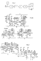
- the device comprises a current source 1, a vibration sensor 2, an amplifier 3, a high-pass filter 4, a low-pass filter 5, a converter 6, an output to a logic circuit (digital part) 7 and a buffer output 8 intended, for example, for a recorder and a milliammeter 9.
- the vibration signal is picked up by a quartz accelerometer 2 compatible with the control device which is described in the present specification and to which it is connected by the IN plug.
- the vibration signal is amplified up to 500 times in two stages.
- the first step of continuously adjustable amplification is carried out in device 10 with the factor 1 to 50, the second step with factor 1 or 10 in device 11.
- the amplification factors are chosen by means of potentiometers 12 and 13 .
- the amplified signal is sent to a filter intended to eliminate on the one hand the high frequencies (device 5) due to noise and control by thyristors not shown in the attached figures and on the other hand the parasitic low frequencies (device 4 in Figure 2B) induced by the hydraulic system, which is also not shown.
- the signal is rectified in the AC-DC converter 6, whose output voltage is integrated over time ( Figure 3).
- An adjustment of the direct current deviation is provided so that a zero input voltage corresponds to a zero output voltage.
- a second amplifier 6 ′ shown in FIG. 3 is intended to obtain a DC voltage acceptable for the digital part of the device.
- the rectified vibration signal is sent to three comparators 14, 15 and 16 in which it is compared to the displayed relative vibration levels for which we want the wheel speed to change (comparators 14 and 15) or an alarm device is engaged (comparator 16).
- the reference voltages of the first two comparators 14 and 15 are produced by voltage dividers adjusted by encoder wheels 17 and 18 and when the vibration signal is greater than or equal to the displayed value, the comparator output is high (5V) .
- the comparator 16 whose reference voltage is adjusted by a potentiometer 19, determines the maximum alarm level that the vibration signals cannot cross without stopping the grinder.
- a first trigger circuit 20 generates a pulse when the input level (from the comparator) has remained high for more than 400 milliseconds in order to avoid untimely changes in speed conditions generates a pulse for each of the vibration signals received and remained high enough.
- a second trigger circuit 21, analogous to the first, generates a pulse, when the input level has remained high for more than 400 milliseconds.
- a data selection device 22 lets pass either the "high” pulses or the “low” pulses depending on the state of a speed selector.
- a delay device 23 consisting of a circuit which, when it receives a pulse generates a new pulse whose duration is adjustable in a time interval ranging from 5 seconds to 5 minutes, (Fig. 6) sends this pulse to a speed selector 24.
- the speed selector 24 consists of a Flip-Flop, which changes state at each period during the birth of the rising edge of an input pulse generated by the circuit 23
- the pulse generated by one of the tripping circuits 20 or 21 activates the timer 23 and reverses the state of the speed selector 24 and the selection device 22.
- the speed selector 24 will remain locked in its position during the duration of the pulse generated by the timing device 23.
- the digital part also includes a speed switch consisting of a relay 25, actuated by the speed selector 24 and which controls the speed change of the grinding wheel.
- the assembly is designed in such a way that the grinding wheel rotates at a lower speed when the relay 25 is at rest and higher when the relay 25 is energized.
- a restart circuit 27 At the end of the delay period of the device 23, a restart circuit 27 generates a pulse which it sends to the gates 28 and 29 which, when the two inputs are high, transmitting the latter to the delay device in order to reset it.
- This state is encountered, for example, when at a high speed of rotation of the grinding wheel, the vibration level is higher than the trigger level associated with it.
- the digital part is shown in more detail in FIGS. 5, 6, 7 and 8.
- the vibration signal is supplied to the three comparators 14, 15 and 16.
- the reference voltages of the first two comparators 14 and 15 are produced by voltage dividers, regulated by encoder wheels 17, 18.
- the voltage dividers for the units and the tens are made from precision resistors 30 (1%). Their mutual influence is eliminated by two buffers 31, then the two voltages are added ( Figures 7 and 8).
- the voltage dividers can be adjusted using the adjustment potentiometers 32.
- the compensation voltage is adjusted using an adjustment potentiometer 33.
- a relay 36 'controlling the alarm device is actuated via a transistor T2.
- Each of the trigger circuits 20, 21 comprises two monostable multivibrators C15a, C15b and C16a, C16b and a gate C17a respectively C17b consisting of integrated circuits, assembled so as to generate a pulse, when the level at the input has remained high for a sufficient time interval. This interval must be greater than 400 milliseconds.
- the rising edge activates the first monostable multivibrator C15a (fig. 5) which emits a 400 ms pulse.
- a second monostable multivibrator C15b is activated and it in turn emits a pulse, is even when passing from a lower reference level to activate a first multivibrator C16a emitting a pulse of 400 ms and capable of activating a second multivibrator C16b.
- Doors C19a, C19b and C20a form the data selection device 22. Depending on the state of a Flip-Flop C24, door C19a or C19b will be open.
- the pulses supplied by the integrated circuits C19a and C19b are reversed in order to be able to use the "AND " gates C20a and C20b as the "OR" gate.
- the falling edge of the pulse via immediately engage the timing device C22 which emits a pulse whose duration is adjustable by means of a potentiometer 34. This pulse will reverse the Flip-Flop C24 via the inverter C21a and the gate C20c.
- the Flip-Flop C24 remains blocked and this blocking is signaled to the user by a lamp 35.
- the time delay device will then block the Flip-Flop of the selection device for a period of time of predetermined duration varying from 5 s to 5 min.
- the output of the timing device 23 is also connected to monostable multivibrators C23a and C23b, this in order to restart the timing device with a slight delay, at least when the door C18d is open.
- a switch 41 connected to the Flip-Flop allows manual change of the wheel speed.
- An alarm device 36 consisting of a relay 36 ′ controlled by the comparator 16 signals the presence of vibrations of level greater than or equal to the ultimate tolerated level and possibly stops the grinding machine.
- the speed selector 24 blocked by the timing device 23 influences the data selection device 22, so that that this one lets pass only impulses of the lower level.
- the output of the comparator 15 is high (5 volts).
- the trigger circuit 21 emits a pulse.
- This pulse is transmitted by the data selection device 22 to the delay device 23.
- This pulse activates the delay device 23 and reverses the state of the speed selector 24.
- This inversion of state of the speed selector 24 excites the relay 26 constituting the speed switch 25 and causes the change of speed of rotation of the grinding wheel.
- the data selection device 22 is reversed. This device then only lets through the pulses coming from the comparator 14 of the vibration signals with the high reference voltage.
- the time delay device 23 prevents any further variation in the speed of the grinding wheel during a time interval of predetermined duration.
- the trigger device 20 When the vibration signal reaches the reference voltage displayed via the encoder wheel, the trigger device 20 emits a pulse which is transmitted by the data selection device 22 to the timing device 23. This pulse triggers the timer 23 and reverses the speed selector 24.
- the monostable multivibrator 27 is connected to the doors 28, 29 as illustrated in FIG. 4.
- n ° i.e. to choose a maximum level of vibrations and when, a priori, there is no information on the value of this level, it is necessary to correct a part of those for which rectification operations are undertaken. It is only on the basis of these indications that adjustments can be made.
- variable speed drive includes a frequency converter.
- the speed variation is obtained by varying at the start either a voltage, a current, or a resistance for example using a potentiometer.
- the device according to the invention can adapt to three possibilities.
Landscapes
- Engineering & Computer Science (AREA)
- Mechanical Engineering (AREA)
- Grinding Of Cylindrical And Plane Surfaces (AREA)
- Constituent Portions Of Griding Lathes, Driving, Sensing And Control (AREA)
- Grinding-Machine Dressing And Accessory Apparatuses (AREA)
- Electrical Discharge Machining, Electrochemical Machining, And Combined Machining (AREA)
- Finish Polishing, Edge Sharpening, And Grinding By Specific Grinding Devices (AREA)
- Details Of Aerials (AREA)
- Measurement Of The Respiration, Hearing Ability, Form, And Blood Characteristics Of Living Organisms (AREA)
- Threshing Machine Elements (AREA)
Claims (7)
Priority Applications (1)
| Application Number | Priority Date | Filing Date | Title |
|---|---|---|---|
| AT83870123T ATE32192T1 (de) | 1982-12-16 | 1983-11-25 | Verfahren und vorrichtung zum schleifen irgendeines werkstuecks bei materialabhebung mittels eines schleifsteines. |
Applications Claiming Priority (2)
| Application Number | Priority Date | Filing Date | Title |
|---|---|---|---|
| BE0/209743A BE895368A (fr) | 1982-12-16 | 1982-12-16 | Procede et dispositif pour rectifier une piece quelconque par enlevement de matiere a l'aide d'une meule |
| BE209743 | 1982-12-16 |
Publications (2)
| Publication Number | Publication Date |
|---|---|
| EP0116267A1 EP0116267A1 (de) | 1984-08-22 |
| EP0116267B1 true EP0116267B1 (de) | 1988-01-27 |
Family
ID=3843585
Family Applications (1)
| Application Number | Title | Priority Date | Filing Date |
|---|---|---|---|
| EP83870123A Expired EP0116267B1 (de) | 1982-12-16 | 1983-11-25 | Verfahren und Vorrichtung zum Schleifen irgendeines Werkstücks bei Materialabhebung mittels eines Schleifsteines |
Country Status (4)
| Country | Link |
|---|---|
| EP (1) | EP0116267B1 (de) |
| AT (1) | ATE32192T1 (de) |
| DE (1) | DE3375464D1 (de) |
| ES (1) | ES8504000A1 (de) |
Families Citing this family (2)
| Publication number | Priority date | Publication date | Assignee | Title |
|---|---|---|---|---|
| GB2268895B (en) * | 1992-07-18 | 1995-06-28 | Litton Uk Ltd | Grinding method and apparatus |
| US6085121A (en) * | 1997-09-22 | 2000-07-04 | Design & Manufacturing Solutions, Inc. | Device and method for recommending dynamically preferred speeds for machining |
Family Cites Families (4)
| Publication number | Priority date | Publication date | Assignee | Title |
|---|---|---|---|---|
| US3634664A (en) * | 1969-04-04 | 1972-01-11 | Bendix Corp | Adaptive and manual control system for machine tool |
| GB1304186A (de) * | 1969-10-04 | 1973-01-24 | ||
| DE2042138C3 (de) * | 1970-08-25 | 1974-02-14 | Gebrueder Boehringer Gmbh, 7320 Goeppingen | Verfahren zum Verhindern regenerativen Ratterns bei der spanabhebenden Bearbeitung eines Werkstücks und Einrichtung zum Durchführen des Verfahrens |
| DE2520946A1 (de) * | 1975-05-10 | 1976-11-18 | Scharmann & Co | Verfahren zur verhinderung oder beseitigung von ratterschwingungen der arbeitsspindel von werkzeugmaschinen und einrichtung zur durchfuehrung dieses verfahrens |
-
1983
- 1983-11-25 AT AT83870123T patent/ATE32192T1/de not_active IP Right Cessation
- 1983-11-25 DE DE8383870123T patent/DE3375464D1/de not_active Expired
- 1983-11-25 EP EP83870123A patent/EP0116267B1/de not_active Expired
- 1983-12-07 ES ES527856A patent/ES8504000A1/es not_active Expired
Non-Patent Citations (3)
| Title |
|---|
| ENGINEERS' DIGEST, vol. 37, no. 9, septembre 1976, D.A. MILNER: "A review of adaptive control", pages 15-23 * |
| R.SNOEYS :"Onstabiliteit van het Slijpproces", Centrum voor het Wetenschappelijk en Technisch Onder zoek der Metaalverwerkende Nijverheid, Brüssel, Juli 1966 * |
| VDI ZEITSCHRIFT, vol. 119, no. 6, mars 1977, H. GRAB: "Ratterfreies Arbeiten mit Bohrstangen durch periodische Drehzahlvariation", pages 309-314 * |
Also Published As
| Publication number | Publication date |
|---|---|
| EP0116267A1 (de) | 1984-08-22 |
| ATE32192T1 (de) | 1988-02-15 |
| ES527856A0 (es) | 1985-04-16 |
| ES8504000A1 (es) | 1985-04-16 |
| DE3375464D1 (en) | 1988-03-03 |
Similar Documents
| Publication | Publication Date | Title |
|---|---|---|
| FR2608766A1 (fr) | Systeme et procede de commande automatique du gain pour moniteur de machine-outil | |
| EP0362449B1 (de) | Werkzeugmaschine zum Ultraschallschleifen | |
| US6191038B1 (en) | Apparatus and method for chemical/mechanical polishing | |
| EP0642399B1 (de) | Schleifscheiben abrichtverfahren und vorrichtung zur anwendung desselben | |
| EP1703829A1 (de) | Für standby- oder reaktionszustand ausgeführtes elektrisches haushaltslebensmittelzubereitungsgerät | |
| JP3031345B2 (ja) | 研磨装置及び研磨方法 | |
| EP0116267A1 (de) | Verfahren und Vorrichtung zum Schleifen irgendeines Werkstücks bei Materialabhebung mittels eines Schleifsteines | |
| JP5036977B2 (ja) | ブラシユニット | |
| FR2693499A1 (fr) | Procédé pour maintenir immergé dans l'eau d'une piscine un dispositif automatique de nettoyage de piscines, et dispositif correspondant. | |
| BE895368A (fr) | Procede et dispositif pour rectifier une piece quelconque par enlevement de matiere a l'aide d'une meule | |
| JPH11320376A (ja) | 研磨装置及び研磨方法 | |
| FR2545028A1 (fr) | Procede pour dresser des meules | |
| FR2503434A1 (fr) | Dispositif d'entrainement d'un ruban tel qu'un dispositif d'entrainement d'une bande magnetique | |
| WO2015075330A1 (fr) | Procede de controle d'un instrument endodontique pour soins canalaires | |
| EP0089899B1 (de) | Verfahren und Anordnung zur Erfassung und Korrektur des Schlupfes der Räder von Schienentriebfahrzeugen | |
| FR2524020A1 (fr) | Machine a laver le linge a moyens de detection de balourds | |
| FR2733449A1 (fr) | Procede et appareil de rectification de pieces | |
| EP0163800B1 (de) | Verfahren und Vorrichtung zur Elektroerosionspolierung | |
| FR2493628A1 (fr) | Dispositif d'arret de la rotation d'un moteur | |
| US4182037A (en) | Honing stone attachment for dental handpiece | |
| CH316871A (fr) | Machine-outil | |
| RU2023132394A (ru) | Устройство и способ размалывания продукта | |
| JP4417053B2 (ja) | レーザーハイコンセントレーションフォーミング方法及びシステム | |
| FR2862493A1 (fr) | Egrappoir comportant un rotor rotatif et vibrant | |
| JPH07223162A (ja) | 研磨布のドレッシング方法及びその装置 |
Legal Events
| Date | Code | Title | Description |
|---|---|---|---|
| PUAI | Public reference made under article 153(3) epc to a published international application that has entered the european phase |
Free format text: ORIGINAL CODE: 0009012 |
|
| AK | Designated contracting states |
Designated state(s): AT CH DE FR GB IT LI LU NL SE |
|
| 17P | Request for examination filed |
Effective date: 19840827 |
|
| ITF | It: translation for a ep patent filed | ||
| GRAA | (expected) grant |
Free format text: ORIGINAL CODE: 0009210 |
|
| AK | Designated contracting states |
Kind code of ref document: B1 Designated state(s): AT CH DE FR GB IT LI LU NL SE |
|
| REF | Corresponds to: |
Ref document number: 32192 Country of ref document: AT Date of ref document: 19880215 Kind code of ref document: T |
|
| GBT | Gb: translation of ep patent filed (gb section 77(6)(a)/1977) | ||
| REF | Corresponds to: |
Ref document number: 3375464 Country of ref document: DE Date of ref document: 19880303 |
|
| PLBE | No opposition filed within time limit |
Free format text: ORIGINAL CODE: 0009261 |
|
| STAA | Information on the status of an ep patent application or granted ep patent |
Free format text: STATUS: NO OPPOSITION FILED WITHIN TIME LIMIT |
|
| PG25 | Lapsed in a contracting state [announced via postgrant information from national office to epo] |
Ref country code: LU Free format text: LAPSE BECAUSE OF NON-PAYMENT OF DUE FEES Effective date: 19881130 |
|
| 26N | No opposition filed | ||
| PGFP | Annual fee paid to national office [announced via postgrant information from national office to epo] |
Ref country code: CH Payment date: 19901019 Year of fee payment: 8 |
|
| PGFP | Annual fee paid to national office [announced via postgrant information from national office to epo] |
Ref country code: LU Payment date: 19901029 Year of fee payment: 8 Ref country code: DE Payment date: 19901029 Year of fee payment: 8 Ref country code: AT Payment date: 19901029 Year of fee payment: 8 |
|
| PGFP | Annual fee paid to national office [announced via postgrant information from national office to epo] |
Ref country code: SE Payment date: 19901115 Year of fee payment: 8 Ref country code: FR Payment date: 19901115 Year of fee payment: 8 |
|
| PGFP | Annual fee paid to national office [announced via postgrant information from national office to epo] |
Ref country code: GB Payment date: 19901122 Year of fee payment: 8 |
|
| ITTA | It: last paid annual fee | ||
| PGFP | Annual fee paid to national office [announced via postgrant information from national office to epo] |
Ref country code: NL Payment date: 19901130 Year of fee payment: 8 |
|
| EPTA | Lu: last paid annual fee | ||
| PG25 | Lapsed in a contracting state [announced via postgrant information from national office to epo] |
Ref country code: GB Effective date: 19911125 Ref country code: AT Effective date: 19911125 |
|
| PG25 | Lapsed in a contracting state [announced via postgrant information from national office to epo] |
Ref country code: SE Effective date: 19911126 |
|
| PG25 | Lapsed in a contracting state [announced via postgrant information from national office to epo] |
Ref country code: LI Effective date: 19911130 Ref country code: CH Effective date: 19911130 |
|
| PG25 | Lapsed in a contracting state [announced via postgrant information from national office to epo] |
Ref country code: NL Effective date: 19920601 |
|
| NLV4 | Nl: lapsed or anulled due to non-payment of the annual fee | ||
| GBPC | Gb: european patent ceased through non-payment of renewal fee | ||
| PG25 | Lapsed in a contracting state [announced via postgrant information from national office to epo] |
Ref country code: FR Effective date: 19920731 |
|
| REG | Reference to a national code |
Ref country code: CH Ref legal event code: PL |
|
| PG25 | Lapsed in a contracting state [announced via postgrant information from national office to epo] |
Ref country code: DE Effective date: 19920801 |
|
| REG | Reference to a national code |
Ref country code: FR Ref legal event code: ST |
|
| EUG | Se: european patent has lapsed |
Ref document number: 83870123.3 Effective date: 19920604 |